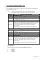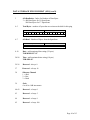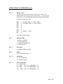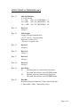
1
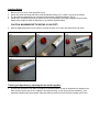
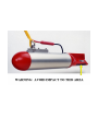
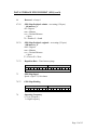
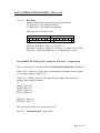
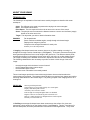
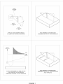
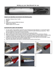
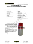
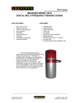
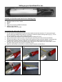
Setting up your SportScan® for use
Unpack your SportScan and check for the following parts:
1.
2.
3.
4.
5.
SportScan Sidescan Sonar Towfish
Shackle
Cable
Floppy Disk containing WIN881SS Software
Software User’s Manual
*Ballast weights are not included
Connecting the cable to the SportScan
1. The rear section of the SportScan houses the sonar transducers and the electronics. To remove this section
from the Aluminum ballast housing tube it is necessary to extract the plastic retaining snap ring (Fig.1). This is
best accomplished by using a pair of needle nose pliers.
2. The rear section may now be slid out and away from the housing tube (Fig.2).
3. Apply a small amount of silicon grease to the rubber part of the male pins on the electronics bulkhead.
4. Check the orientation of the two connector halves and carefully but firmly push them together. A retaining strap
is molded into the female connector. Slip this over and behind the male connector for security (Fig.3).
5. Install the rear section back into the Ballast housing, taking care to fit the cable into the slot provided. Thread
the plastic snap ring back into the groove completely (Fig.4).
6. Attach the cable thimble to the Aluminum housing using the shackle provided (Fig.5).
Fig.1
Fig.2
Fig.4
Fig.5
Fig.3
Installing Ballast
1.
2.
3.
4.
Remove the nose cone of the SportScan (Fig.6).
Extract the ballast mounting plate from inside the ballast housing (Fig.7). Make a note of the orientation.
The SportScan is designed to use conventional 3lb lead diving weights as ballast* (Fig.8).
Add at least 15-20lbs of ballast as far forward and as low as possible, securing the weights using tie-wraps.
Adding more weight will allow the SportScan to be towed at a greater depth.
CAUTION: MAXIMUM DEPTH RATING IS 100 FEET!
5. Slide the ballast plate back into the housing, reinstall the nose cone, and fit the plastic snap ring (fig.9).
Fig.6
Fig.7
Fig.8
Fig.9
Trimming the SportScan by adjusting the tow shackle position
•
Immerse the SportScan in still water, and adjust the shackle position so that the SportScan lies parallel to the
water surface (ensure that no air is trapped in the ballast housing, as this will give a false indication). If the
SportScan wanders while being towed, adjust the shackle position so that the towfish is slightly nose heavy.
SportScan
445-016 AUGUST 2002-REVISED AUGUST 2005
IMAGENEX SPORTSCAN
APPLICATIONS:
•
•
•
•
•
•
•
Underwater Archaeology
Sunken Timber Recovery
Search & Recovery
Surveying
Law Enforcement Work
Scientific Research
Environmental Survey
FEATURES:
•
•
•
•
•
•
•
•
•
•
•
Very user friendly
Lightweight and extremely portable
Inexpensive
23 m (75’) tow cable included
High resolution
Up to 240 m (800’) total coverage
GPS interface
Speed correction
Height and length measurements
4 user selectable colour tables
XTF Conversion program (optional)
The Imagenex SportScan is an
affordable dual channel, highresolution, digital side-scan sonar
geared toward the sport diving
market. Operate the SportScan
directly from your laptop or desktop
PC. All that is needed is a 12 VDC
power source. Connect a GPS
receiver for latitude and longitude
coordinates.
HARDWARE
SPECIFICATIONS:
FREQUENCY
TRANSDUCER
TRANSDUCER BEAM WIDTH
RANGE RESOLUTION
MAX. OPERATING DEPTH
MAX. CABLE LENGTH
INTERFACE
CONNECTOR
POWER SUPPLY
DIMENSIONS
WEIGHT: In Air
In Water
BALLAST
MATERIALS
FINISH
Specifications subject to
change without notice
330 kHz or 330 / 800 kHz
One transducer per side, tilted down 20°
330 kHz: 1.8° x 60°
800 kHz: 0.7° x 30°
Both sides displayed: Range scale ÷ 250
Single side displayed: Range scale ÷ 500
30 m (100’)
60 m (200’)
RS-232 serial interface @ 115.2 kbps
Wet mateable (Impulse LPMBH-4-MP)
10 – 16 VDC at 300 mA max.
114 mm (4.5”) diameter x 833 mm (32.8”) length
4.5 kg (10 lbs)
not including ballast
1.2 kg (2.7 lbs)
Standard diver belt weights (readily available at dive shops)
Polyurethane & 6061-T6 Aluminum
Clear anodized
www.imagenex.com
Copyright © 2002 - 2013
Imagenex Technology Corp.
SOFTWARE
SPECIFICATIONS:
Win881ss.exe
WINDOWS™ OPERATING SYSTEM
MODES
RANGE SCALES
Windows™ 95, 98, Me, NT*, 2000*, XP*, Vista*
Side Scan
15 m, 30 m, 60 m, 90 m, and 120 m
(50’, 100’, 200’, 300’, and 400’)
(filename).81s
FILE FORMAT
GPS INPUT (4800, N, 8, 1)
NMEA 0183 FORMATS:
RECOMMENDED
MINIMUM COMPUTER
REQUIREMENTS:
GLL, GGA, VTG, RMC
100 MHz Pentium
16 MB RAM
1 GB Hard Disk
800 x 600 x 256 colour graphics
* Requires Win881ss.exe v2.00 or higher (Free upgrade available for older versions – Contact Imagenex)
ORDERING
INFORMATION:
30 m unit w / 23 m SportScan tow cable
330 / 800 kHz
60 m (200’) SportScan tow cable
XTF Converter
(Imagenex .81s to XTF)
Standard
Option
Option
Option
881-000-150
-005
-017
-019
Product and company names listed are trademarks or trade names of their respective companies.
2
SportScan
445-016
www.imagenex.com
Model 881 SPORTSCAN Digital Sidescan Sonar
Frequently Asked Questions
What can I use to power the SportScan?
The SportScan requires a DC voltage between 10 and 16 volts for proper operation
(+12VDC @ 0.5A max.). A 12 volt lab power supply could be used, or you can
connect to the 12VDC wiring on your boat. A 12 volt car battery could also be used.
The RED wire from the SportScan cable should be connected to the Positive terminal
and the BLACK wire should be connected to the Negative terminal.
How deep can I tow the SportScan?
The maximum allowable depth for the SportScan towfish is 100 feet (30 meters).
Will the Win881SS program operate using Windows NT, 2000 and XP?
Yes, Win881SS (v2.00 and higher) will operate using Windows 95/98/Me/NT/2000
and XP. Versions below v2.00 will only operate on Windows 95/98 and Me.
What do I do when I see the message “Win881SS requires 256 Color Mode!”
Win881SS (v3.00 and lower) must operate in the 256 color mode (8 Bits). From the
Start menu, highlight ‘Settings’ and click on ‘Control Panel’. Double-click the
‘Display’ icon to invoke the Display Properties page. Click the ‘Settings’ tab and then
select ‘256 Colors’ from the Colors drop down list. Press OK.
How do I connect the SportScan and a GPS receiver to my laptop if there is only one
or no serial ports?
You can add serial ports to your laptop by using the PCMCIA slots or the USB port.
There are many PCMCIA cards available that provide an RS-232 interface to the
computer. One example is the Model 232PCC from B&B Electronics (www.bbelec.com). This card provides a DB-9 male connector which the SportScan cable will
directly plug into. B&B also makes the Model US1000A and Model UC232A USB to
RS-232 Converters and IOGEAR (www.iogear.com) makes the Model G-UC232A. All
of these devices come with driver files which allows Windows to configure the device
as an additional COM port.
Frequently Asked Questions (con’t)
Why does my GPS work with my NAV program but not with Win881SS?
The serial port used for the GPS input must not be in use by another program when
invoking Win881SS (only one program can have access to any one serial port). Ensure
that the GPS receiver unit is setup to output $GPGLL, $GPGGA or $GPRMA
messages at 4800 bps, No Parity, 8 Data Bits and 1 Stop Bit.
Why does the “No Data at COM1” message always flash when using my Toshiba
Laptop computer?
The serial ports on Toshiba laptops behave differently than on other laptops. From the
Start menu, highlight ‘Settings’ and click on ‘Control Panel’. Double-click the
‘System’ icon to invoke the System Properties page. Click the ‘Device Manager’ tab
and Double-click the ‘Ports (COM & LPT)’ setting. Double-click ‘Communications
Port (COM1)’ to invoke the Communications Port (COM1) Properties page. Click the
‘Port Settings’ tab and enter the following settings:
Bits per second = 115200
Data bits = 8
Parity = None
Stop bits = 1
Flow control = Xon / Xoff
Click the ‘Advanced…’ button to invoke the Advanced Port Settings page. Set the
‘Receive Buffer’ to the Low(1) setting (left-most position) and press the ‘OK’ button.
You can also try disabling the ‘Use FIFO buffers’ check box.
Another solution is to use a USB to RS-232 serial adapter (like the Model G-UC232A
from www.iogear.com) rather than the dedicated serial port on the rear panel of the
laptop.
Frequently Asked Questions (con’t)
How far off the bottom should I tow the SportScan?
The SportScan altitude should be 10 to 20 percent of the operating range above the
bottom. For example, if the operating range is set to 90 meters, the SportScan should
be 9 to 18 meters above the bottom (remember the 30 meter maximum depth limit!).
When the bottom is nearly flat, you can tow close to the bottom. When the bottom is
not flat, tow at a higher altitude.
Note: If you are towing in unknown area where there could be obstructions, it is best
to tow the SportScan just beneath the surface to avoid collisions with unknown
objects.
Can the SportScan be damaged in any way by operating it out of the water?
No, the SportScan can not be damaged by operating it in air. In fact, all units receive a
24 hour burn-in test (in air) before shipping. However, if you do operate it in air (i.e.
on the deck of your boat), ensure that the unit is not sitting in direct sunlight for
extended periods of time.
How much hard drive space is required for saving the .81S SportScan data files?
Storage consumption is typically about 10–15MB per hour.
How fast can I tow the SportScan?
The best images are developed when towing at about 2-3 knots. The slower the tow
speed, the more echoes you will get from any one target and the better the sonar image
will appear. Depending on the type of boat you are using, you might need to run as
slow as the boat will travel.
Frequently Asked Questions (con’t)
What is Speed Correction?
Speed Correction is a process which adds or removes data lines from the sonar image
in order to produce a 1:1 aspect ratio on the screen (so a square target appears square
and not rectangular). The SportScan transmits and receives data at a fixed rate
depending on operating range. If the tow speed increases, the distance traveled is
greater, but because the rate remains constant, the sonar image will be compressed in
time (along track). Speed Correction will compensate for this compression by adding
lines in the data at the appropriate places.
Using the speed from your GPS receiver will give the best results as it will constantly
update in real time. Using manual speed entry will suffice if a GPS receiver is not
available.
What Gain setting should I use?
The Gain setting is like a volume control on a stereo, the higher the number, the
‘louder’ the image will be. The type of seafloor beneath you will determine the gain
setting that you should use. When the Color Table is set to ‘Color’, the sidescan data
will be displayed using blue, green, orange, yellow, white a red colors. Weak returns
will be blue and strong returns will be red. A muddy bottom will be displayed in blue
with a Gain of less than about 16dB. Whereas, a rocky bottom might be red at the
same Gain setting. In this case, you should lower the gain to maybe less than 6dB. The
key is to set the Gain such that only very strong returns show up in the red color. If the
Gain is set too high, most of the image will be saturated with red which limits the
dynamic range of the system, meaning you won’t be able to ‘see’ the difference
between a target lying on the bottom and the bottom itself. Normally, the Gain should
be set anywhere between 6dB and 20dB (but please experiment). Once the gain is set,
using the ‘Grey’ Color Table is useful for seeing different shapes on the bottom and
shadows will be more apparent.
Frequently Asked Questions (con’t)
When collecting sidescan data, why does the “No Data at COM1” message flash
once and a while when using a Laptop computer?
If any of the laptop’s Power Management settings are enabled (i.e. maximum battery
life, hard drive shut down, etc…), the laptop has to monitor these activities at the same
time that the real time sonar data is being acquired. This can cause the Win881ss.exe
program to miss data from the SportScan Head and the message might flash. Ensure
that all Power Management settings are disabled in the BIOS settings and through the
Control Panel ‘Power’ settings.
Why does the SportScan image display stop scrolling when I connect the GPS?
If the GPS speed is 0 knots and Speed Correction is enabled, the display will not
scroll. Disable Speed Correction while the GPS coordinates are not changing.
IMAGENEX TECHNOLOGY CORP.
13FEB07
MODEL 881 SPORTSCAN
Single or Dual Frequency Digital Sidescan Sonar
Software User’s Manual
WIN881SS.EXE: VERSION 3.07 (Win 9x/NT/2000/XP/Vista)
OVERVIEW
WIN881SS is a Windows program that controls, displays and records data from the
single or dual frequency Model 881 SportScan. The program uses an RS-232 COM port
(115200,N,8,1) for communication to/from the SportScan. A second RS-232 COM port
(4800,N,8,1 or 9600,N,8,1) can be used for receiving Lat/Lng coordinates and ships
speed and heading from any GPS receiver. The SportScan can be operated at different
ranges and gains. The Windows display mode must be at least 800 x 600 pixels with
small fonts selected.
SCREEN LAYOUT
The main screen of WIN881SS is the sonar data window. The sonar data from the port
and starboard channels of the SportScan pan across the screen from right to left to
generate a ‘picture’ of the seafloor. Below the sonar window there are controls for
changing the Range, Gain and Current Sidescan Channel. Other items include readouts
for date/time, Lat/Lng coordinates, ships speed and heading, target cursor range, current
frequency and a control for displaying real time data from the SportScan or playback data
from a file. The Main Menu has various features including switches for operating
frequency, sonar data color, target length and height measurement, speed correction
(from GPS or manual) and a pop-up zoom window.
OPERATION
To operate the SportScan, ensure that the DB9 connector from the tow cable is connected
to the RS-232 serial port on your PC. Apply nominal +12VDC (+10 to +16VDC) to the 2
power wires (+V to RED, -V to BLACK) using a DC power supply capable of supplying
a current of 0.5 Amps. Run the program WIN881SS.EXE and select the button DATA
FROM 'HEAD' on the lower left-hand side of the display. Ensure that the correct COM
port is selected via the Com Ports Menu.
Page 1 of 15
MAIN MENU
File Menu
Data From...
to display real time data from the connected SportScan
Head or previously recorded data from a SportScan File.
Record Start (Stop)...
opens a File Name Dialog Box so the user can enter a
filename for logging SportScan data (ping by ping)
complete with date/time and Lat/Lng coordinates. The file
extension is always '.81S'. The filename and current size
(kbytes) of the file are displayed at the top of the screen.
File recording continues until Record Stop is selected.
Available only when DATA FROM 'HEAD' is active.
Playback...
opens a File Name Dialog Box so the user can select and
playback a previously recorded '.81S' SportScan file.
Available only when DATA FROM 'FILE' is active.
Copy Start (Stop)...
opens a File Name Dialog Box so the user can enter a
filename to generate a new ‘.81S’ file that can be used for
making smaller data files from large pre-recorded
SportScan files. The filename and current size (kbytes) of
the file are displayed at the top of the screen. File copying
continues until Copy Stop is selected. Available only
when DATA FROM 'FILE' is active.
Save Screen...
opens a File Name Dialog Box so the user can enter a
filename for saving the screen as a '.BMP' Windows
BITMAP file.
Exit
writes current configuration to file (WIN881SS.INI),
closes the program and exits to Windows.
Color Table Menu
Color
Grey
Reverse Grey
Brown
color table used for mapping the echo data amplitude to a
color for display. Color depth is 107 colors ranging from
Black (lowest level) through Blue, Green, Orange,
Yellow, White and Red (highest level).
107 shades of grey (White on Black).
107 shades of grey (Black on White).
107 shades of brown (Brown on Black).
Page 2 of 15
MAIN MENU (con't)
Com Ports Menu
SportScan Head
to select the serial communications port (COM1-COM32)
for communicating with the SportScan. Ports that are
already used or unavailable are not displayed. All
communication through this port is at 115200 bits per
second, No Parity, 8 Data Bits and 1 Stop Bit.
GPS Input
to select the serial communications port (COM1-COM32)
for receiving Lat/Lng ships position coordinates and ships
speed and heading information from a GPS receiver. For
ships position, this port can accept the NMEA 0183
$GPGLL string, the $GPGGA string or the $GPRMC
string. If Speed from GPS is selected in the Misc Menu,
and GLL or GGA is selected, the $GPVTG string will be
used for the speed and heading displays. If RMC is
selected, the speed and heading information from the
$GPRMC string is used. All communication through this
port is at 4800,N,8,1. The baud rate can be changed to
9600,N,8,1 by setting GPSBaudRate=1 in the
WIN881SS.INI file. The default is GPSBaudRate=0 for
4800,N,8,1.
If the program detects only one available COM port (i.e.
on a laptop computer), this port will be reserved for
communications with the SportScan only and GPS Input
will not be available.
As default on most computers, COM1/COM3 share IRQ4
(interrupt request #4) and COM2/COM4 share IRQ3.
Ensure that the COM port you select for GPS Input does
not share its IRQ with the SportScan COM port. This
could cause the program to hang up!
GLL
to use Lat/Lng coordinates from the $GPGLL string.
$GPVTG is used for speed/heading.
GGA
to use Lat/Lng coordinates from the $GPGGA string.
$GPVTG is used for speed/heading.
RMC
to use Lat/Lng coordinates and speed/heading information
from the $GPRMC string
Page 3 of 15
MAIN MENU (con't)
Misc Menu
Units
to change the units of measurement from Meters to Feet.
Grid
to display the range division lines on the sonar display.
Clear Screen Now
to clear all echo data from the sonar display.
Diagnostics
displays the Diagnostics pop-up window. This window
displays the header information from the SportScan.
Zoom
displays a x3 pixel zoom pop-up window. A rectangular
area about the cursor is displayed in this window. Click
the left mouse button once to capture the zoom window
contents. Click again to release the capture.
Manual Speed
used to enter the towing speed of the boat (in knots) if
GPS speed is not available. The speed is needed in order
to perform Speed Correction on the sonar data. Not
available if Speed from GPS is selected.
Speed from GPS
used for sonar data Speed Correction. Select this function
if the $GPRMC or $GPVTG strings are available from
your GPS receiver. If none of these strings are available,
enter the tow speed using the Manual Speed entry.
Speed Correction
use this function to plot the SportScan data with a 1:1
aspect ratio. The displayed along track distance will be
the same as the slant range echo distance. Circular targets
will appear circular.
Along Track Marks
used to display the along track tick marks on the sonar
data display. If Speed Correction is selected, the distance
between the along track marks will be the same number of
pixels as the distance between the range divison grid
lines.
Page 4 of 15
MAIN MENU (con't)
Options Menu
Target Calculations:
Target Length
to measure the distance between two targets. Position the
target cursor anywhere on the sonar image display and
press the right mouse button. A second target cursor is
displayed with a rubber-banded line drawn between the
two cursors. The distance between the two cursors is
displayed in meters (or feet). Press the right mouse button
again to remove the second cursor.
Target Height
to measure the approximate height off the bottom of a
target (assuming a flat bottom). When selected, the cursor
will display ‘Target Height - Click on Target’. At this
point, position the target cursor on the target of interest
and press the left mouse button. A vertical rubber-banded
line is drawn from the cursor position to the beginning of
the transmit pulse with the message ‘Click on Bottom
Return’. Position the cursor so that the end of the rubberbanded line is at the beginning of the bottom return (the
end of the water column) and press the left mouse button
again. The message ‘Click on Shadow Start’ is now
displayed. Position the cursor at the beginning of the
shadow that the target has cast and press the left mouse
button. The message ‘Shadow End – Height = ???M’ is
displayed. Move the cursor to the end of the shadow to
display the height measurement. Press the left mouse
button again to begin a new measurement.
Frequency
to select the operating frequency (High or Low) for the
connected Dual Frequency SportScan. The high frequency
selection will produce a higher resolution picture, but
overall range will be limited to about 60 meters (200 feet)
per side. If a Single Frequency SportScan is connected,
the high frequency selection is not available.
Page 5 of 15
MAIN MENU (con't)
Channel Balance…
allows the user to balance the port and starboard channels
during real time operations (DATA FROM ‘HEAD’). A
maximum of 6dB between channels can be obtained. The
value for each channel is displayed on the main screen
below the Hold Button. The channel balance number is
saved in the ‘.81S’ record file as well as in the
WIN881SS.INI file.
About Menu
About...
displays an about box showing the software version and
date of this program. Contact information for Imagenex
Technology Corp. is also displayed.
Page 6 of 15
ON SCREEN SWITCHES
DATA FROM 'HEAD'
to display real time data from the connected SportScan
Head.
DATA FROM 'FILE'
to display data from a previously recorded '.81S'
SportScan file.
Hold
to hold or freeze the display.
Range
to change the sonar operating range. Available ranges are:
15m (50ft)
30m (100ft)
60m (200ft)
90m (300ft)
120m (400ft)
Available only when DATA FROM ‘HEAD’ is active.
Gain
to change the gain of the SportScan receiver amplifiers.
Increase to get higher return levels, decrease to get lower
return levels. The Gain can be adjusted from 0dB to 40dB
in 1dB increments. Available only when DATA FROM
‘HEAD’ is active.
Channel
to display the data from the Port side channel, Starboard
side channel or both channels.
TrackBar
to re-position the file pointer during file playback.
Available only when DATA FROM 'FILE' is active.
REC Pause
to suspend the recording of SportScan data while still
allowing the user to view real time data. When paused, a
flashing red message is displayed to remind the user that
data is not being recorded. Available only when DATA
FROM 'HEAD' is active and a file is open for recording.
Plot Spd
to increase or decrease the file playback speed. Available
only when DATA FROM 'FILE' is active.
Page 7 of 15
KEYBOARD SWITCHES
The following switches are selected via keyboard entry (case insensitive):
G
to change the Gain of the SportScan receiver amplifiers.
When the 'G' key is pressed, the Key Command Entry
Box (above the Lat/Lng window) displays the prompt:
Gain: ? dB. Type in a valid gain number (0-40) and press
<Enter> to change to the new gain value. If the entered
gain is not valid or the <Esc> key is pressed, the current
gain will be used. Available only when DATA FROM
'HEAD' is active.
H
to hold or freeze the display.
R
to change the operating range of the SportScan. When the
'R' key is pressed, the Key Command Entry Box is
displayed with the following prompt: Range: ? M
(meters) or Range: ? FT (feet). Type in a valid range
number: 15(50), 30(100), 60(200), 90(300) or 120(400) in
meters or (feet) using the numeric keys and then press
<Enter> to change to the new range. If the entered range
is not valid or the <Esc> key is pressed, the current range
will be used. Available only when DATA FROM 'HEAD'
is active.
P
to pause or resume recording. Available only when
DATA FROM 'HEAD' is active and a file is open for
recording.
Arrow Keys
the arrow keys can be used to fine tune the position of the
target cursor.
MESSAGES
No Data at COM?
- no power to the SportScan Head
- cable not connected
- SportScan COM port set to the wrong port number
Lat/Lng ‘N/A’
- GPS receiver output not connected to serial port
- GPS receiver is not sending data
- GPS receiver not set for 4800,N,8,1
- GPS Input COM port set to the wrong port number
- GPS receiver not sending the $GPGLL, $GPGGA
or $GPRMC NMEA 0183 message strings
Page 8 of 15
DATA STORAGE FILE FORMAT (.81S)
When recording the SportScan data to a .81S file, the following bytes are appended and
saved to the file every ping:
Note:
V6 SportScans output 400 data points in total (200 points per side)
V7 SportScans output 500 data points in total (250 points per side)
Byte #
0 to 99
100 to 111
112 to 511
512
513 TO 637
638 to 639
Byte #
0 to 99
100 to 111
112 to 611
612
613 TO 637
638 to 639
V6 SportScan Byte Description
File Header (100 Bytes)
Sonar Return Data Header (12 Bytes)
Sonar Return Echo Data (400 Bytes)
Sonar Return Termination Byte (1 Byte, always 0xFC)
Zero Fill (125 Bytes)
Pointer To Previous Ping
The last 2 bytes of this ping contain a 16-Bit number that is the sum of
the number of bytes for this ping and the number of bytes for the
previous ping. This number can be used for reverse playback
synchronization.
Number of bytes to previous ping = ((Byte 638)<<8) | (Byte 639)
V7 SportScan Byte Description
File Header (100 Bytes)
Sonar Return Data Header (12 Bytes)
Sonar Return Echo Data (500 Bytes)
Sonar Return Termination Byte (1 Byte, always 0xFC)
Zero Fill (25 Bytes)
Pointer To Previous Ping
The last 2 bytes of this ping contain a 16-Bit number that is the sum of
the number of bytes for this ping and the number of bytes for the
previous ping. This number can be used for reverse playback
synchronization.
Number of bytes to previous ping = ((Byte 638)<<8) | (Byte 639)
FILE HEADER
Bytes 0 through 99 contain the following File Header information:
0
1
2
ASCII '8'
ASCII '1'
ASCII 'S'
Page 9 of 15
DATA STORAGE FILE FORMAT (.81S) (con't)
3
nToReadIndex - Index for Number of Data Bytes
3 = 400 Data Bytes for V6 SportScans,
500 Data Bytes for V7 SportScans
4-5
Total Bytes - number of bytes that are written to the disk for this ping
7
6-7
6
5
Byte 4
4 3
2
1
0 7
640
6
5
Byte 5
4 3
2
1
0
2
1
0
nToRead - Number of Bytes from the SportScan
7
6
5
Byte 6
4 3
2 1 0 7 6 5
413 for V6, 513 for V7
Byte 7
4 3
8-19
Date - null terminated date string (12 bytes)
"DD-MMM-YYYY"
20-28
Time - null terminated time string (9 bytes)
"HH:MM:SS"
29-36
Reserved - always 0
37
Reserved – always 16
38
Sidescan Channel
1 = Stbd
2 = Port
3 = Both
39
Gain
0 to 40 in 1 dB increments
40-42
Reserved – always 0
43
Reserved – always 5
44
Reserved – always 9
45
Reserved – always 100
Page 10 of 15
DATA STORAGE FILE FORMAT (.81S) (con't)
46
Reserved – always 0
47-58
GPS Ships Position Latitude – text string (12 bytes)
“_dd.mm.xxx_N”
dd = Degrees
mm = Minutes
xxx = Decimal Minutes
_ = Space
N = North or S = South
59-70
GPS Ships Position Longitude – text string (12 bytes)
“ddd.mm.xxx_E”
ddd = Degrees
mm = Minutes
xxx = Decimal Minutes
_ = Space
E = East or W = West
71-72
Repetition Rate – Time between pings
7
6
5
Byte 71
Byte 72
4 3 2 1 0 7 6 5 4 3 2
Repetition Rate (ms)
73
GPS Ships Speed
Speed = (Byte 73)/10 in knots
74-75
GPS Ships Heading
7
76
6
5
Byte 74
Byte 75
4 3 2 1 0 7 6 5 4 3 2
Heading * 10 (in degrees)
1
0
1
0
Operating Frequency
0 = Low Frequency
1 = High Frequency
Page 11 of 15
DATA STORAGE FILE FORMAT (.81S) (con't)
77
Channel Balance
7
V
6
5
Byte 77
4
3
2
Channel Balance (0 to 60)
1
0
If V = 0, use Channel Balance of 30 = 0dB for both channels
If V = 1, Channel Balance:
Stbd Gain = [(Byte 77 & 0x7F)-30]/10 in dB
Port Gain = -[(Byte 77 & 0x7F)-30]/10 in dB
78
WIN881SS RecordingVersion
0 = v2.01 and lower
1 = v3.00 and higher (for V7 SportScans)
79-99
Reserved - always 0
Page 12 of 15
DATA STORAGE FILE FORMAT (.81S) (con't)
SONAR RETURN DATA HEADER
Bytes 100 through 111 contain the following Sonar Return Data Header
information:
100
101
102
ASCII 'I'
ASCII 'G' or ASCII 'H' if V7 SportScan
ASCII 'X'
103
Head ID – always 0x10
104
Serial Status
Bit 0
- 0 = V6 (or lower SportScan), 1 = V7 SportScan
Bit 1
-0
Bit 2
-0
Bit 3
-0
Bit 4
-0
Bit 5
-0
Bit 6
- 1 = Switches Accepted
Bit 7
- 1 = Character Overrun
105
SportScan Type
0 = Single Frequency
1 = Dual Frequency
106
Sidescan Channel
1 = Starboard
2 = Port
3 = Both
107
Range
15, 30, 60, 90 or 120 meters
108
Reserved - always 0
109
Reserved – always 0
Page 13 of 15
DATA STORAGE FILE FORMAT (.81S) (con't)
110 - 111 Data Bytes
Number of Data Bytes returned from the SportScan head
V6: Data Bytes = 412 (Header included)
V7: Data Bytes = 500 (Header not included)
Data Bytes (LO), Data Bytes (HI)
7
0
6
Byte 110
5 4 3 2 1
Data Bytes (LO)
0
7
0
6
Byte 111
5 4 3 2 1
Data Bytes (HI)
0
L
Data Bytes High Byte = (Byte 111 & 0x7E)>>1
Data Bytes Low Byte = [((Byte 111 & 0x01)<<7) | (Byte 110 & 0x7F)]
Data Bytes = (Data Bytes High Byte<<8) | Data Bytes Low Byte
SONAR RETURN ECHO DATA (example for IGX mode – V6 SportScans)
Bytes 112 through 511 contain the following Sonar Return Echo Data information:
If Byte 106 = 1 (Stbd) or 2 (Port), there are 400 range bytes starting at range 0 (Byte
112), ending at range 399 (Byte 511)
If Byte 106 = 3 (Both), there are 200 range bytes per channel. The range bytes
alternate from channel to channel.
i.e.
Stbd[0] = Byte 112
Port[0] = Byte 113
Stbd[1] = Byte 114
Port[1] = Byte 115
.
.
Stbd[199] = Byte 510
Port[199] = Byte 511
The sonar data intensity level varies from 0 to 127.
Byte 512
Termination Byte - always 0xFC
Page 14 of 15
DATA STORAGE FILE FORMAT (.81S) (con't)
SONAR RETURN ECHO DATA (example for IHX mode – V7 SportScans)
Bytes 112 through 611 contain the following Sonar Return Echo Data information:
If Byte 106 = 1 (Stbd) or 2 (Port), there are 500 range bytes starting at range 0 (Byte
112), ending at range 499 (Byte 611)
If Byte 106 = 3 (Both), there are 250 range bytes per channel. The range bytes
alternate from channel to channel.
i.e.
Stbd[0] = Byte 112
Port[0] = Byte 113
Stbd[1] = Byte 114
Port[1] = Byte 115
.
.
Stbd[249] = Byte 610
Port[249] = Byte 611
The sonar data intensity level varies from 0 to 127.
Byte 612
Termination Byte - always 0xFC
Page 15 of 15
IMAGENEX TECHNOLOGY CORP.
12NOV02
MODEL 881 SPORTSCAN DIGITAL SIDESCAN SONAR
SERIAL INTERFACE SPECIFICATION (v7.00)
OVERVIEW
The Model 881 Sportscan Digital Sidescan Sonar communicates over a 3-wire RS-232
serial data transmission line. To interrogate the Sportscan and receive echo data, a Switch
Data Command string is sent via a serial command program at a baud rate of 115200 bps,
No Parity, 8 Data Bits and 1 Stop Bit. When the Switch Data command is accepted, the
Sportscan transmits, receives and sends its return data back to the commanding program.
SWITCH DATA COMMAND
The Sportscan accepts up to 27 bytes of switch data from the serial interface and must see
the switch data header (2 bytes: 0xFE and 0x44 HEX) in order to process the switches.
The Sportscan will stop accepting switch data when it sees the termination byte (0xFD
HEX), or 28 bytes (whichever comes first). The termination byte must be present for the
Sportscan to process the switches.
Note: the Termination Byte is the only switch value allowed
to have a value of 0xFD. All other switches should be set
higher or lower than 0xFD (253 Decimal) so they are not
interpreted as a termination byte!
Byte #
0–7
Description
Head
Range Reserved Hold
Master/ Sidescan
ID
0
Slave
Mode
8 – 15
Start
LOGF Absorp- Port Gain Stbd Gain Reserved Pulse Reserved
Gain
tion
Balance Balance
0
Length
0
16 – 23 Reserved Reserved Reserved
Data
Data
Up
Reserved Reserved
0
0
0
Points
Bits
Baud
0
0
24 – 26 Switch
FreqTerm.
Delay
uency
0xFD
Table 1
0xFE
0x44
Model 881 Sportscan Digital Sidescan Sonar Switch Data Command
Page 1 of 8
SWITCH DATA COMMAND (con't)
BYTE DESCRIPTIONS
Note: All Byte values are shown in decimal unless noted with a '0x' (hexadecimal) prefix.
Byte 0
Switch Data Header (1st Byte)
Always 0xFE (254 decimal)
Byte 1
Switch Data Header (2nd Byte)
Always 0x44 (68 decimal)
Byte 2
Head ID
0x10 for Model 881-000-XXX Sportscan Digital Sidescan Sonar
Byte 3
Range
5 ranges available:
15 = 15m
30 = 30m
60 = 60m
90 = 90m
120 = 120m
- units must be meters
Byte 4
Reserved
Always 0
Byte 5
Hold
Bit 0
Bit 1
Bit 2
Bit 3
Bit 4
Bit 5
Bit 6
Bit 7
- 1 = Hold (or pause) operation, 0 = Resume
-0
-0
-0
-0
-0
-0
-0
Page 2 of 8
SWITCH DATA COMMAND (con't)
Byte 6
Master / Slave
The Sportscan can be operated as a master or as a slave. The
default mode on power-up is Slave mode (Bit 6 = 1). Slave mode
allows the user to command the Sportscan to transmit and send its
return data at any given time.
Bit 0
Bit 1
Bit 2
Bit 3
Bit 4
Bit 5
Bit 6
Bit 7
- 1 = Transmit if Bit 6 = 1 (Slave Mode)
- 1 = Send Data if Bit 6 = 1 (Slave Mode)
-0
-0
-0
-0
- 0 = Master, 1 = Slave
-0
- use 0x43 for Slave Mode
Byte 7
Sidescan Mode
3 modes are available:
1 = Port channel only
2 = Starboard channel only
3 = Both channels
Byte 8
Start Gain
0 to 40dB in 1dB increments
Byte 9
LOGF
This value should always = 1
Byte 10
Absorption
10 = Low Frequency
20 = High Frequency
Byte 11
Port Gain Balance
71 to 141 Percent
71 = -3dB,
100 * [10^(-3dB/20dB)] = 71
100 = 0dB,
100 * [10^(0dB/20dB)] = 100
141 = +3dB, 100 * [10^(3dB/20dB)] = 141
Page 3 of 8
SWITCH DATA COMMAND (con't)
Byte 12
Stbd Gain Balance
71 to 141 Percent
71 = -3dB,
100 * [10^(-3dB/20dB)] = 71
100 = 0dB,
100 * [10^(0dB/20dB)] = 100
141 = +3dB, 100 * [10^(3dB/20dB)] = 141
Byte 13
Reserved
Always 0
Byte 14
Pulse Length
Length of acoustic transmit pulse.
0 to 255 µsec in 1 µsec increments
Do not use a value of 253!
- 100 µsec is a typical value
Byte 15
Reserved
Always 0
Byte 16
Reserved
Always 0
Byte 17
Reserved
Always 0
Byte 18
Reserved
Always 0
Byte 19
Data Points
40
- 400 data points are returned by the Sportscan
The return data will have an ASCII 'IGX' header.
50
- 500 data points are returned by the Sportscan
The return data will have an ASCII 'IHX' header.
Byte 20
Data Bits
Resolution (number of data bits) of the returned echo data
8 - Data width = 8 Bits, 1 data point per byte
Page 4 of 8
SWITCH DATA COMMAND (con't)
Byte 21
Up Baud
The Sportscan receives switch data at 115200 baud, but can transmit
its return data at various baud rates. The Up Baud value sets the
Sportscan to transmit at a new baud rate. The default Up Baud value on
power-up is 115200 baud.
0x0B
0x03
0x0C
0x04
0x02
0x05
0x06
- 9600 baud
- 14400 baud
- 19200 baud
- 28800 baud
- 38400 baud
- 57600 baud
- 115200 baud
Byte 22
Reserved
Always 0
Byte 23
Reserved
Always 0
Byte 24
Switch Delay
The Sportscan can be commanded to pause (from 0 to 510 msec)
before sending its return data to allow the commanding program
enough time to setup for serial reception of the return data.
0 to 255 in 2 msec increments
Do not use a value of 253!
Byte 25
Operating Frequency
0 = Low Frequency
1 = High Frequency
Byte 26
Termination Byte
The Sportscan will stop looking for Switch Data when it sees this byte.
Always 0xFD (253 decimal)
Page 5 of 8
SPORTSCAN RETURN DATA
Every ping, the Sportscan returns a 12 Byte header, up to 500 points of echo data
(depending on the Switch Data command that was sent) and a terminating byte value of
0xFC. The total number of bytes (N) returned will be 413 or 513.
Byte #
0 to 5
Description
ASCII
ASCII
ASCII
Head
Serial
'I'
'G' or ‘H’
'X'
ID
Status
Channel Range Reserved Reserved
Data
0
0
Bytes
Echo Data
400 or 500 Data Bytes
Term.
0xFC
6 to 11
12 to
(N-2)
N-1
Table 2
Type
Data
Bytes
Model 881 Sportscan Digital Sidescan Sonar Return Data
BYTE DESCRIPTIONS
Note: All Byte values are shown in decimal unless noted with a '0x' prefix.
N = total number of return bytes
Byte 0 - 2
Imagenex Return Data Header
ASCII 'IGX'
'I' = 0x49, 'G' = 0x47, 'X' = 0x58
In response to a Switch Data Command with Data Points = 40
8 Data Bits: N = 413 (400 Points)
ASCII 'IHX'
'I' = 0x49, 'H' = 0x48, 'X' = 0x58
In response to a Switch Data Command with Data Points = 50
8 Data Bits: N = 513 (500 Points)
Byte 3
Head ID
0x10 for Model 881-000-XXX Sportscan Digital Sidescan Sonar
Page 6 of 8
SPORTSCAN RETURN DATA (con't)
Byte 4
Serial Status
Bit 0 - 1 = V7 SportScan (IHX mode available)
Bit 1 - 0
Bit 2 - 0
Bit 3 - 0
Bit 4 - 0
Bit 5 - 0
Bit 6 - 1 = Switches Accepted
Bit 7 - 1 = Character Overrun
Byte 5
SportScan Type
0 = Single Frequency
1 = Dual Frequency
Byte 6
Sidescan Channel
1 = Starboard
2 = Port
3 = Both
Byte 7
Range
Sportscan operating range: 15, 30, 60, 90 or 120 Meters
Byte 8
Reserved
Always 0
Byte 9
Reserved
Always 0
Byte 10 - 11
Data Bytes
Number of Echo Data Bytes returned by the SportScan head
Data Bytes (LO), Data Bytes (HI)
7
0
6
Byte 10
5 4 3 2 1
Data Bytes (LO)
0
7
0
6
Byte 11
5 4 3 2 1
Data Bytes (HI)
0
L
Data Bytes High Byte = (Byte 11 & 0x7E)>>1
Data Bytes Low Byte = [((Byte 11 & 0x01)<<7) | (Byte 10 & 0x7F)]
Data Bytes = (Data Bytes High Byte<<8) | Data Bytes Low Byte
Page 7 of 8
SPORTSCAN RETURN DATA (con't)
Byte 12
Start of Echo Data
(N-13) Bytes of data
Example is for IHX mode
If Sidescan Channel (Byte 6) = 1 or 2 (Stbd or Port Channel Only),
there are 500 points/channel:
1st Range point = Byte 12
2nd Range point = Byte 13
3rd Range point = Byte 14
4th Range point = Byte 15, etc. ...
If Sidescan Channel (Byte 6) = 3 (Both Channels),
there are 250 points/channel:
1st Range point (Stbd) = Byte 12
1st Range point (Port) = Byte 13
2nd Range point (Stbd) = Byte 14
2nd Range point (Port) = Byte 15, etc. ...
Byte (N-2)
End of Echo Data
Byte (N-1)
Termination Byte
0xFC
Page 8 of 8
SONAR THEORY AND APPLICATIONS
EXCERPT FROM IMAGENEX MODEL 855
COLOR IMAGING SONAR USER'S MANUAL
IMAGENEX TECHNOLOGY CORP.
#209 - 1875 BROADWAY ST.
PORT COQUITLAM, B.C. V3C 4Z1
CANADA
TEL: (604) 944-8248
FAX: (604) 944-8249
ABOUT YOUR SONAR
TERMINOLOGY:
The following is an explanation of the basic terms used by Imagenex to describe their sonar
techniques.
Color: The different colors used to represent the varying echo return strengths.
Echo: The reflected sound wave
Echo Return: The time required for the echo to return to the source of the sound
Sonar: The principle used to measure the distance between a source and a reflector (target)
based on the echo return time
Target: The object that you wish to obtain information about.
IMAGING:
Fan shaped beam
Scans surfaces at shallow angles, usually through a horizontal angle
Displays color images or pictures
Complete echo strength information for each point
Primarily for visual interpretation
In Imaging a fan-shaped sonar beam scans a given area, by either rotating or moving in a
straight line, through a series of small steps, (see Figure 1). The beam's movement through the
water generates points that form a sonar image of the given area. The different colored points,
representing the time (or slant range) of each echo return, plot a line on a video display screen.
The image, consisting of the different colored lines, depicts the various echo return strengths.
The following characteristics are necessary to produce a visual or video image of the sonar
image:
!
!
!
!
the angle through which the beam is moved is small
the fan-shaped beam has a narrow angle
the transmitted pulse is short
the echo return information is accurately treated
These visual images provide the viewer with enough data to draw conclusions about the
environment being scanned. The operator should be able to recognize sizes, shapes and surface
reflecting characteristics of the chosen target. The primary purpose of the imaging sonar is as a
viewing tool.
PROFILING:
Narrow pencil shaped beams
Scans surfaces at a steep angle usually on a vertical plane
Displays individual points or lines
Accurately cross-sections a surface
Echo strength for each point higher than a set threshold
Digitizes a data set for interfacing with external devices
Data set is small enough to be manipulated in a small computer
Primarily a measurement tool
In Profiling a narrow pencil-shaped sonar beam scans across the surface of a given area
generating a single profile line on the display monitor, (see Figure 2). This line, consisting of a
few thousand points, accurately describes the cross-section of the targeted area. A key to the
Profiling process is the selection of the echo returns for plotting. The sonar selects the echo
returns, typically one or two returns for each "shot", based on a given criterion for the echo return
strength and the minimum profiling range. The information gathered from the selection criteria
forms a data set containing the range and bearing figures. An external device, such as a
personal computer or data logger, accesses the data set through an RS-232 interface with the
sonar.
The profile data is useful for making pen plots of bottom profiles, trench profiles, internal and
external pipeline profiles. The primary purpose of the profiling sonar is as a quantitative
measuring tool.
USING AN IMAGING SONAR ON AN ROV
The imaging sonar is a useful substitute for a positioning system on an ROV. Without an imaging
sonar, an ROV relies on traveling underwater to bring new targets into view. With an imaging
sonar, instead of traveling it is more useful to spend some time with the vehicle sitting on the
bottom while the sonar scans the surrounding area. Scanning a large area takes only a short
time, and the vehicle pilot can quickly assess the nature of the surrounding area. The ability to
"see" a long distance underwater allows the pilot to use natural or man-made features and targets
as position references.
The combination of an imaging sonar and an ROV leads to fast and effective training in sonar
interpretation. If the ROV pilot is searching for a particular object, recognition can take place
directly from the sonar image. In other cases a number of potential targets may be seen. A pilot
can sharpen his sonar interpretation skills by viewing these targets with the vehicle's video
camera and correctly identify them.
INTERPRETATION OF SONAR IMAGES
In many cases the sonar image of a target will closely resemble an optical image of the same
object. In other cases, the sonar image may be difficult to interpret and quite unlike the expected
optical image. The scanning process used to create a sonar image is different from the process
used by the human eye or a camera to produce optical images. A sonar image will always have
less resolution than an optical image, due to the nature of the ultrasonic signals used to generate
it.
Generally, rough objects reflect sound well in many directions and are therefore good sonar
targets. Smooth angular surfaces may give a very strong reflection in one particular direction, but
almost none at all in other directions. Some objects, such as smooth plane surfaces, may be
difficult to see with a sonar. They can act as a perfect mirror (so called specular reflectors),
reflecting the sonar pulse off in unexpected directions, never to return. This happens to people
visually, when they see an object reflected in a window. The human eye deals with such
reflections daily but it is surprising to see the same thing occur with a sonar image. As with
normal vision, it is often useful to scan targets from different positions, to help identify them. A
target which is unrecognizable from one direction may be quite easy to identify from another.
It is very important to note that the ranges shown to the targets on the sonar image are "slant"
ranges. Usually the relative elevations of the targets are not known, only the range from the
transducer. This means that two targets, which are displayed in the same location on the screen
may be at different elevations. For example, you might see a target on the bottom, and a target
floating on the surface in the same place. By analyzing the shadows you can estimate the height
of objects above the bottom. An example of this calculation is shown in Figure 4.
The diagrams following this chapter are examples of the sonar scanning process. Studying the
diagrams will help you to better understand the images that you see. A basic knowledge of this
process will help users to interpret what otherwise might be confusing images.