1
User’s
Manual
Model OR8ERG
KCl Refillable type ORP Sensor
IM 12C04K01-01E
R
IM 12C04K01-01E
5th Edition
<INTRODUCTION>
i
INTRODUCTION
This manual covers the OR8ERG KCl Refillable type ORP Sensor.
Other related items are described in the following manuals.
Model
Title
IM No.
PH8HG
Guide-pipe Holder
IM 12B7M2-01E
PH8HF, PH8HFF
Flow-Through Type Holder
IM 12B07N01-01E
PH8HS, PH8HSF
Submersion Type Holder
IM 12B07M01-01E
HH350G
Well Bucket Type Holder
IM 19H1B1-01E
PB350G
Float Type Holder
IM 19H1E1-01E
PB360G
Vertical Type Float Holder
IM 19H1E2-01E
PH450G
pH/ORP Converter
IM 12B07C05-01E
PH202G, S
pH/ORP Transmitter
IM 12B07D02-01E
PH202SJ
TIIS Intrinsic safe pH/ORP Transmitter
IM 12B07D02-11E
FLXA202, FLXA21
2-Wire Liquid Analyzer
IM 12A01A02-01E
WTB10-PH¨
Terminal Box
IM 19D01B01-01E
OR8TBG
Terminal Box
IM 12C04W01-01E
OR8AX
Accessories for ORP Meter
IM 12C04W02-01E
Media No. IM 12C04K01-01E 5th Edition : Nov. 2015 (YK)
All Rights Reserved Copyright © 1996, Yokogawa Electric Corporation
IM 12C04K01-01E
5th Edition : Nov.10,2015-00
ii
<INTRODUCTION>
For the safe use of this equipment
n Notes on Handling User’s Manuals
• Please hand over the user’s manuals to your end users so that they can keep the user’s
manuals on hand for convenient reference.
• Please read the information thoroughly before using the product.
• The purpose of these user’s manuals is not to warrant that the product is well suited to any
particular purpose but rather to describe the functional details of the product.
• No part of the user’s manuals may be transferred or reproduced without prior written
consent from YOKOGAWA.
• YOKOGAWA reserves the right to make improvements in the user’s manuals and product at
any time, without notice or obligation.
• If you have any questions, or you find mistakes or omissions in the user’s manuals, please
contact our sales representative or your local distributor.
n Safety, Protection, and Modification of the Product
• In order to protect the system controlled by the product and the product itself and ensure
safe operation, observe the safety precautions described in this user’s manual. We assume
no liability for safety if users fail to observe these instructions when operating the product.
• If this instrument is used in a manner not specified in this user’s manual, the protection
provided by this instrument may be impaired.
• If any protection or safety circuit is required for the system controlled by the product or for
the product itself, prepare it separately.
• Be sure to use the spare parts approved by Yokogawa Electric Corporation (hereafter
simply referred to as YOKOGAWA) when replacing parts or consumables.
• Modification of the product is strictly prohibited.
• The following safety symbols are used on the product as well as in this manual.
WARNING
This symbol indicates that an operator must follow the instructions laid out in this manual in order
to avoid the risks, for the human body, of injury, electric shock, or fatalities. The manual describes
what special care the operator must take to avoid such risks.
CAUTION
This symbol indicates that the operator must refer to the instructions in this manual in order to
prevent the instrument (hardware) or software from being damaged, or a system failure from
occurring.
CAUTION
This symbol gives information essential for understanding the operations and functions.
NOTE
This symbol indicates information that complements the present topic.
n Warning and Disclaimer
The product is provided on an “as is” basis. YOKOGAWA shall have neither liability nor
responsibility to any person or entity with respect to any direct or indirect loss or damage arising
from using the product or any defect of the product that YOKOGAWA can not predict in advance.
IM 12C04K01-01E
5th Edition : Nov.10,2015-00
iii
<INTRODUCTION>
After-sales Warranty
n Do not modify the product.
n During the warranty period, for repair under warranty consult the local sales
representative or service office. Yokogawa will replace or repair any damaged
parts. Before consulting for repair under warranty, provide us with the model
name and serial number and a description of the problem. Any diagrams or
data explaining the problem would also be appreciated.
l If we replace the product with a new one, we won’t provide you with a repair report.
l Yokogawa warrants the product for the period stated in the pre-purchase quotation
Yokogawa shall conduct defined warranty service based on its standard. When the
customer site is located outside of the service area, a fee for dispatching the maintenance
engineer will be charged to the customer.
n In the following cases, customer will be charged repair fee regardless of
warranty period.
• Failure of components which are out of scope of warranty stated in instruction manual.
• Failure caused by usage of software, hardware or auxiliary equipment, which Yokogawa
Electric did not supply.
• Failure due to improper or insufficient maintenance by user.
• Failure due to modification, misuse or outside-of-specifications operation which Yokogawa
does not authorize.
• Failure due to power supply (voltage, frequency) being outside specifications or abnormal.
• Failure caused by any usage out of scope of recommended usage.
• Any damage from fire, earthquake, storms and floods, lightning, disturbances, riots, warfare,
radiation and other natural changes.
n Yokogawa does not warrant conformance with the specific application at the
user site. Yokogawa will not bear direct/indirect responsibility for damage due
to a specific application.
n Yokogawa Electric will not bear responsibility when the user configures the
product into systems or resells the product.
n Maintenance service and supplying repair parts will be covered for five years
after the production ends. For repair for this product, please contact the
nearest sales office described in this instruction manual.
IM 12C04K01-01E
5th Edition : Nov.10,2015-00
Blank Page
v
<CONTENTS>
Model OR8ERG
KCl Refillable type ORP Sensor
IM 12C04K01-01E 5th Edition
CONTENTS
INTRODUCTION..............................................................................................i
For the safe use of this equipment..............................................................ii
After-sales Warranty....................................................................................iii
1.
Specification.............................................................................................. 1-1
2.
1.1
Standard Specifications.................................................................................... 1-1
1.2
Model and Suffix codes..................................................................................... 1-2
1.3
External Dimensions......................................................................................... 1-3
Installation.................................................................................................. 2-1
2.1
2.2
2.3
3.
Preparation for Installation............................................................................... 2-1
2.1.1
Unpacking and Inspection.................................................................. 2-1
2.1.2
Installing Holder.................................................................................. 2-1
2.1.3
Installing Associated Instruments....................................................... 2-1
Requirements for mounting the ORP Sensor................................................. 2-2
2.2.1
In case of installing the PH8HG Guide-pipe Holder........................... 2-2
2.2.2
Installing Sensor in PH8HS Submersion Holder................................ 2-3
2.2.3
Installing Sensor in PH8HF Flow-through Holder............................... 2-6
ORP Sensor Cable Wiring Procedure.............................................................. 2-7
2.3.1
Connecting Sensor Cable to Terminal Box......................................... 2-7
2.3.2
Connecting Sensor Cable to Two-wire ORP Transmitter................... 2-8
2.3.3
Connecting Sensor Cable to Four-wire ORP Converter.................... 2-9
Maintenance on operation........................................................................ 3-1
3.1
3.2
Operation and Periodic Maintenance.............................................................. 3-1
3.1.1
Calibrating ORP Sensor Using Checking Solutions........................... 3-1
3.1.2
Cleaning Indicator Electrode and Liquid Junction.............................. 3-1
3.1.3
Refilling Sensor with KCl Solution...................................................... 3-1
Replacing Consumable Parts........................................................................... 3-3
3.2.1
Replacing Liquid Junction................................................................... 3-3
3.2.2
Replacing O-rings for Indicator Electrode........................................... 3-4
Customer Maintenance Parts List........................................CMPL12C03K01-01E
Revision Information................................................................................................i
IM 12C04K01-01E
5th Edition : Nov.10,2015-00
Blank Page
1-1
< 1. Specification >
1.
Specification
The Model OR8ERG KCl Refillable ORP Sensor features maintainability which involves no KCl
solution coming out of the liquid junction.
This sensor can be mounted on either an PH8HF flow-through holder or an PH8HS submersion
holder. The sensor can be submerged up to a maximum of 3 meters.
1.1
Standard Specifications
Measurement:
Oxidation-reduction potential of a solution
Measurement principle:Metallic electrode method
Measuring range:
-1500 to 1500 mV
Installation:
Mounting in PH8HS submersion holder
Mounting in PH8HG guide-pipe holder
Mounting in PH8HF flow-through holder
Note:
If any of the following solutions are measured, install the sensor either in a flow-through or submersion holder.
• A strong acid solution is to be measured (e.g., aqua regia, chromic acid, hypochlorous acid or perchloric acid, etc.).
• The solution contains corrosive gases (e.g., ammonia, chlorine, hydrogen sulfide, etc).
• The solution contains a small percentage of organic solvent or oil.
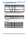
Solution temperature : -5 to 80°C (refer to Table 1)
Table 1.Process Temperature Range
Holder Type
Holder
Material
Cleaner
Solution
pH Range
Solution
Temperature (°C)
PVC
None
-5 to 50
PP
None
-5 to 80
Submersion (PH8HS)
Flow-through (PH8HF)
PP, SS (*1)
None, Provided
Well Bucket (HH350G)
SS (*1)
None, Provided
-5 to 80
PP, SS (*1)
None
-5 to 50
Guide-pipe
(PH8HG)
Float
(PB350G, PB360G)
-5 to 80
2 to 12
Note: PVC: Rigid Polyvinyl, PP: Polypropylene, SS: Stainless Steel
*1:
Stainless steel holder and Stainless steel adapter should be used when the pH value of the solution is pH3 or more acidic.
Solution pressure : under atmospheric pressure to 50 kPa, when using a holder, refer to Table 2.
Table 2.Process Pressure Range
Holder
Process Pressure Range
Submersion
Atmospheric pressure (Submersion depth: Max. 3 m)
Guide-pipe Suspension Float
Atmospheric pressure (Submersion depth: Max.3 m)
Flow-through
Atmospheric pressure to 50 kPa
Note: For flow-through types, refer also to the solution temperature and pressure diagram of Holder IM.
Operating solution depth:
3 m water pressure (max.) under atmospheric pressure
Solution flow velocity: 2 m/s max.
Solution flow rate:
3 to 11 L/min (when the sensor is installed in a flow-through type holder).
Wetted part materials:
Body; Ryton (PPS resin), platinum-glass or gold-epoxy resin, titanium, ceramics, Fluoro rubber (FKM)
Cable; Chlorinated polyethylene rubber (Cable sheath)
Weight:Approx. 0.4 kg (Body)
CAUTION
Select the material of wetted parts with careful consideration of process characteristics. Inappropriate
selection may cause leakage of process fluids, which greatly affects facilities. Considerable care must be
taken particularly in the case of strongly corrosive process fluid such as hydrochloric acid, sulfuric acid,
hydrogen sulfide, and sodium hypochlorite. If you have any questions about the wetted part construction
of the product, be sure to contact Yokogawa.
IM 12C04K01-01E
5th Edition : Nov.10,2015-00
1-2
< 1. Specification >
1.2
Model and Suffix codes
l ORP Sensor
Model
OR8ERG
Electrode
Suffix Code
Option Code
...................................... ......................
-AU
.....................
-PT
.....................
Cable Length
-03
.....................
-05
.....................
-07
.....................
-10
.....................
-15
.....................
-20
.....................
Measuring System
-N
.....................
-E
.....................
-F
.....................
-B
.....................
-G
.....................
Style
*A .....................
*1:
*2:
*3: *4:
*5: Description
KCl Refillable Type ORP Sensor
Gold
Platinum
3m
5m
7m
10 m
15 m
20 m
For OR200/OR400 (*1)
For PH202/FLXA202/FLXA21 (*2)
For FLXA202/FLXA21 (*3)
For OR100 (*4)
For PH450G, PH202/TB (*5)
Style A
Mark band is shown by alphanumeric and fork terminals are used.
Mark band is shown by numeral and pin terminals are used. When terminal box is used, select WTB10-PH1.
Mark band is shown by numeral and M4 ring terminals are used. When terminal box is used, select WTB10-PH5.
The tag which indicated the color, the sign, and the number is attached to the cable of a sensor.
Mark band is shown by numeral and M3 ring terminals are used. When terminal box is used, select WTB10-PH3.
l Accessories
Model
OR8AX
Suffix Code Option Code
.................... .....................
*A
.....................
/STD
/KCLL
/KCLP
/TMP
Style
Option
*1:
Description
Accessories for ORP meter (*1)
Style A
Sensor stand (with mounting bracket for 2-inch pipe)
KCl solution (one 250 mL polyethylene bottle)
KCl powder (three bags, 250 mL solution each)
Thermometer (0 to 100°C)
Including the following:
Two 200 mL polyethylene cups
One cleaning bottle
One pack of quinhydrone reagent powder (three bags, 250 mL solution each)
One 250 mL polyethylene bottle
l Consumables
Part Name
Indicator
electrode
Part Number
Remarks
Platinum
K9142TS
One for OR8ERG, OR8EFG
Gold
K9142TT
One for OR8ERG, OR8EFG
Junction
K9142TH
One for OR8ERG, OR8EFG
KCl solution (3.3mol/L)
K9084LP
Six 250 mL polyethylene bottles
KCl powder (for OR8ERG)
K9020UT
2 bags, 1 bottle of 3.3mol/L KCl, 1 syringe
Reagent for
check
Quinhydrone
K9024EC
3 bags, each for preparation of 250mL
Iron
K9024ED
3 bags, each for preparation of 250mL
IM 12C04K01-01E
5th Edition : Nov.10,2015-00
1.3
1-3
< 1. Specification >
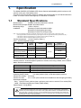
External Dimensions
("-B", "-N": Fork terminal)
GE RE SE G
("-E": Pin terminal)
("-G", "-F": Ring terminal)
15 13 14 16
Unit: mm
15 13 14 16
Cable gland is not included.
Reuse existing gland, or replace.
Cable length: L
Terminal No. and colors
GE
15 (Red)
RE
13 (Brown)
SE
14 (Black)
G
16 (Green)
64
103
Model and codes
L (mm)
Weight (kg)
OR8ERG - - 03 - *A
Approx. 3000
Approx. 0.4
OR8ERG - - 05 - *A
Approx. 5000
Approx. 0.6
OR8ERG - - 07 - *A
Approx. 7000
Approx. 0.7
OR8ERG - - 10 - *A
Approx. 10000
Approx. 1.0
OR8ERG - - 15 - *A
Approx. 15000
Approx. 1.4
OR8ERG - - 20 - *A
Approx. 20000
Approx. 1.8
F1.1.eps
Ø27.5
Ø38
Figure 1.1
OR8ERG Refillable type ORP Sensor
IM 12C04K01-01E
5th Edition : Nov.10,2015-00
Blank Page
2-1
< 2. Installation >
2.
Installation
2.1
Preparation for Installation
2.1.1
Unpacking and Inspection
The Model OR8ERG ORP Sensor is packed at the factory to prevent damage during
transportation. Upon receipt of the sensor, unpack the shipping container and then visually
inspect it for damage. Also check the instrument nameplate on the sensor cable to make sure
that you received the correct sensor.
NOTE
Do not attempt to remove the liquid junction (see Figure 2.2 below), Otherwise, the sensor
internal solution will leak out. Do not let the liquid junction and indicator electrode dry out. To
prevent this, place the protective cap covering the top of the sensor in its original position until the
sensor is installed.
MODEL
OR8ERG - PT- 03 - N*A
No.
Made in Japan
F2.1.ai
Figure 2.1
An Example of Model Number Entering to Nameplate
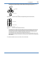
Sensor Body
Grounding Electrode
Indicator Electrode
Liquid Junction
Figure 2.2
2.1.2
F2.2.ai
Names of OR8ERG ORP Sensor Components
Installing Holder
Usually, the ORP Sensor is suspended in a guide pipe or installed in a flow-through or
submersion holder. First install the holder.
2.1.3
Installing Associated Instruments
Make sure that the associated instrument (a ORP transmitter/converter or a junction terminal
box) to which the ORP Sensor cable is connected has already been installed.
IM 12C04K01-01E
5th Edition : Nov.10,2015-00
2.2
2-2
< 2. Installation >
Requirements for mounting the ORP Sensor
2.2.1
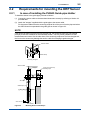
In case of installing the PH8HG Guide-pipe Holder
To install the sensor in the guide pipe, proceed as follows:
(1) Connect the sensor cable to the associated instrument correctly by referring to Section 2.3
provided later.
(2) Attach the "stopper" supplied with the guide pipe to the sensor cable.
Fix the sensor cable so that the sensor tip projects 20 to 30 mm out from the pipe end when
the ORP Sensor is suspended in the guide pipe as shown in Figure 2.3.
NOTE
If the sensor tip does not project out from the pipe end, the measured value may not respond
promptly to the ORP variations of the measured solution. This may cause problems for ORP
measurement and control. On the other hand, if the sensor tip projects too far from the pipe end,
the force on the sensor may damage the sensor cable from scraping it against the pipe.
Sensor Cable
Cable Clamp
Attaching "Stopper"
Sensor Cable
Stopper
2-inch (60.5 mm O.D)
Mounting Pipe
Arm Pipe
Guide Pipe
20 to 30 mm
ORP Sensor
Figure 2.3
Mounting Sensor in Guide Pipe
IM 12C04K01-01E
5th Edition : Nov.10,2015-00
2.2.2
2-3
< 2. Installation >
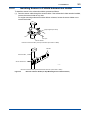
Installing Sensor in PH8HS Submersion Holder
To install the sensor in the submersion holder, proceed as follows:
(1) Pass the sensor cable through the sensor holder. If the submersion holder remains installed,
remove the sensor holder in any case.
For a pipe-mounting submersion holder without a cleaner, loosen the sensor holder nut to
remove the holder.
Right-angled Pipe Clamp
Nut
Arm Pipe
Sensor Holder
Removal of Sensor Holder (Arm Pipe used with option /MS1 or /MS2)
Bracket
Sensor Holder
Sensor Holder Nut
F2.4.ai
Removal of Sensor Holder (Stainless Bracket used with option /MS3 or /MS4)
Figure 2.4
Removal of Sensor Holder (for Pipe Mounting Sensor without Cleaner)
IM 12C04K01-01E
5th Edition : Nov.10,2015-00
2-4
< 2. Installation >
For a flange mounting submersion holder without a cleaner, remove the sensor holder by
loosening the two bolts securing the sensor holder to the flange (see Figure 2.5).
Fixing Bolt
Flange
F2.5.ai
Figure 2.5
Removal of Sensor Holder (for Flange Mounting Sensor without Cleaners)
Clamp (Screw)
Cleaner Holder
Sensor Holder
Figure 2.6
F2.6.ai
Removal of Sensor Holder (with Cleaner)
To install the sensor cable in the sensor holder, first remove the protector screwed onto the
sensor holder end and then remove the protective foam piece (for shipping; thus, it is not
necessary after the sensor is installed in the holder). Pass the sensor cable through the
O-ring then attach the O-ring to the sensor flange (see Figure 2.7).
When passing the sensor cable through the holder, if the inside of the holder is dirty or wet,
take special care to keep the cable dry by covering the sensor cable end with a polyethylene
bag or the like.
For details to install the sensor onto a holder, refer to relevant IMs.
IM 12C04K01-01E
5th Edition : Nov.10,2015-00
2-5
< 2. Installation >
Waterproof Cap Cover
Waterproof Cap
Pull out the sensor cable
Sensor Holder Pipe
Sensor Cable
Insert the sensor and cable
Sponge
(Remove)
O-ring
Flange
Sensor Body
Protector
Figure 2.7
Installing the Sensor Cable
(2) Connect the sensor cable to the associated instrument correctly by referring to Section 2.3.
(3) Screw the protector to fix the sensor to the holder. In this case, remove the protective cap
and secure the protector so that the flange of the sensor compresses the O-ring firmly.
about the installation method.
IM 12C04K01-01E
5th Edition : Nov.10,2015-00
2-6
< 2. Installation >
ORP Sensor
O-ring
Protector
F2.8.ai
Figure 2.8
Installing Sensor in Submersion Holder
(4) Close the waterproof cap, and attach the holder to the arm pipe, flange or cleaner holder
completely.
2.2.3
Installing Sensor in PH8HF Flow-through Holder
To install the sensor in a flow-through holder, proceed as follows:
(1) Connect the sensor cable to the associated instrument. First, remove the sensor fixing nut
and pass the sensor cable through the nut.
ORP Sensor
Sensor Fixing Nut
Figure 2.9
Preparation for Sensor Cable Connection
Properly connect the sensor cable by referring to Section 2.3.
(2) Connect the ORP Sensor to its holder. Remove the protective cap from the sensor. Also
remove the protective foam piece (for shipping - this is not necessary after installing the
sensor) from the holder. Be sure that the liquid junction and indicator electrode are mounted
properly. Insert the sensor tip into the holder and tighten the sensor fixing nut securely (see
Figure 2.10).
IM 12C04K01-01E
5th Edition : Nov.10,2015-00
2-7
< 2. Installation >
ORP Sensor
Fixing Nut
O-ring
Flow-through Holder
2-inch Mounting Pipe
F2.10.ai
Figure 2.10
2.3
Installing Sensor in Flow-through Holder
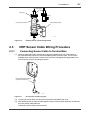
ORP Sensor Cable Wiring Procedure
2.3.1
Connecting Sensor Cable to Terminal Box
(1) Open the cable inlet hole in terminal box using the supplied punch tool. The location of
the cable inlet hole is shown by the circle-shaped groove under the case. The end of the
supplied punch tool is put in the center of this circle and it is tapped with appropriate force.
You can punch out the hole along the groove.
Hole punching tool for wiring
(supplied as accessory)
F2.11.ai
Figure 2.11
How to punch out the wiring hole
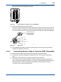
(2) Loosen two screws which are at front of terminal box and detach the cover.
(3) After detaching the nut from the cable gland of sensor cable, pull the cable into the terminal
box from sensor cable inlet hole.
Connect the sensor cable to the terminals.
IM 12C04K01-01E
5th Edition : Nov.10,2015-00
SENSOR
After passing the cable through the nut, check the symbol on each core wire, then connect
each core wire to the corresponding terminal.
CONVERTER
2-8
< 2. Installation >
F2.12.ai
Figure 2.12
Connecting Sensor Cable (In case of the OR8TBG)
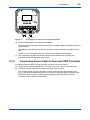
(4) Mount the cable gland in the cable inlet hole.
Put the nut in place, and screw it onto the main body sufficiently. At this time, loosen the cap
so that the cable is not twisted. After fixing the main body, tighten the cap to keep moisture
out of the equipment. However if the cap is screwed up too tight, the cable will be damaged.
Attach the nut in the
direction shown here
(so that it engages
the detent groove).
Nut
Gasket
Main unit
Cap
Figure 2.13
F2.13.ai
Cable Gland
(5) After completing the cable connections, replace the box cover securely, thus preventing
moisture from getting into the case.
2.3.2
Connecting Sensor Cable to Two-wire ORP Transmitter
To connect the sensor cable to the two-wire ORP transmitter, proceed as follows:
(1) Loosen the four screws that tighten the transmitter cover. Then remove the transmitter
cover.
(2) Connect the sensor cables to the relevant terminals of the transmitter:
First, remove the nut from the cable gland. Insert the cable into the right opening for the
wiring. Then pass the cable through the nut, Connect the individual cable conductors to the
relevant terminals correctly by referring to the markings on the individual conductors.
For details, refer to relevant transmitter IMs.
IM 12C04K01-01E
5th Edition : Nov.10,2015-00
2-9
< 2. Installation >
Sensor cable
Figure 2.14
Connecting Sensor Cable to Two-wire ORP Transmitter
(3) Install the cable gland in the wiring hole as follows:
Pass the tip of the cable gland into the opening and completely tighten the gland with the nut
inside the case.
After tightening the gland, secure the cap properly to prevent moisture from getting into the
case.
Caution: Do not overly tighten the cap. Otherwise, the cable may be damaged.
(4) After completing the cable connections, replace the transmitter cover securely, thus
preventing moisture from getting into the case.
2.3.3
Connecting Sensor Cable to Four-wire ORP Converter
To connect the sensor cable to a Four-wire ORP converter, proceed as follows:
(1) Loosen the four screws that tighten the converter cover. Then open the converter cover.
(2) Connect the sensor cables to the relevant terminals of the converter:
First, remove the nut from the cable gland. Insert the cable into the right opening for the
wiring. Then pass the cable through the nut, Connect the individual cable conductors to the
relevant terminals correctly by referring to the markings on the individual conductors.
For details, refer to relevant converter IMs.
IM 12C04K01-01E
5th Edition : Nov.10,2015-00
2-10
< 2. Installation >
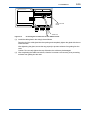
Wiring Terminal
Board
Cable Inlet
Figure 2.15
Connecting Sensor Cable to Four-wire ORP Converter
(3) Install the cable gland in the wiring hole as follows:
Pass the tip of the cable gland into the opening and completely tighten the gland with the nut
inside the case.
After tightening the gland, secure the cap properly to prevent moisture from getting into the
case.
Caution: Do not overly tighten the cap. Otherwise, the cable may be damaged.
(4) After completing the cable connections, close the converter cover securely, thus preventing
moisture from getting into the case.
IM 12C04K01-01E
5th Edition : Nov.10,2015-00
3-1
< 3. Maintenance on operation >
3.
Maintenance on operation
3.1
Operation and Periodic Maintenance
3.1.1
Calibrating ORP Sensor Using Checking Solutions
Dirt attached to the liquid junction or sensitive parts (platinum electrodes) may have an adverse
effect on electromotive force and response characteristics, so ORP sensors require periodic
cleaning for good operating conditions. ORP sensors should be checked and calibrated if the
following conditions are met.
(1) Sensor checks
• If a new ORP sensor is used or the existing sensor has been unused for an extended period
of time.
• When an ORP sensor sensitive part (platinum electrode) or a liquid junction is cleaned.
(2) Calibration
• If sensor electromotive force is outside the allowable ranges.
• If the measured value by the ORP sensor is adjusted to the measured value by other
sensors.
For more detailed information on the calibration procedures, see the separate Instruction
Manuals "Two-wire Liquid Analyzer" (publication no. IM 12A01A02-01E) and "Four-wire pH/ORP
Converter" (publication no. IM 12B07C05-01E).
3.1.2
Cleaning Indicator Electrode and Liquid Junction
Staining of a indicator electrode or liquid junction can cause measurement errors. Therefore, if he
measured solutions tend to stain the electrode, the indicator electrode and liquid junction must
be cleaned periodically - depending on the degree of staining. if the ORP Sensor is installed in a
holder with a cleaner, the sensor is continuously (for an ultrasonic cleaner) or intermittently (for a
jet or brush cleaner) cleaned automatically.
Because of this, sensor cleaning is not usually required.
To clean the indicator electrode or liquid junction, proceed as follows:
● Stains due to suspended Solids, Sticky Materials, Microbes or the like
Using soft tissue paper, wipe the stains off the indicator electrode or liquid junction. In
addition, clean off remaining stains by rinsing with water.
●
Stains due to Oily Materials
Wash off stains by submerging in a neutral detergent solution in a beaker, etc, (for from
several tens of minutes to several hours depending on the degree of staining).
●
Chemical Stains such as due to Metallic Adsorption
Place the indicator electrode or liquid junction in a diluted hydrochloric acid solution (1 to
2%) for several minutes (acid washing).
3.1.3
Refilling Sensor with KCl Solution
The concentration of the KCl solution in the sensor will begin to drop when the saturated
concentration cannot be maintained with the KCl solution from the liquid junction. As the
concentration of the KCl solution decreases, so too does this influence the sensor's performance.
To avoid this, replenish the KCl solution in the sensor before the concentration starts to decrease.
IM 12C04K01-01E
5th Edition : Nov.10,2015-00
< 3. Maintenance on operation >
3-2
The time required for maintaining the saturated concentration of a KCl solution in a sensor is
greatly influenced by the sensor's operating conditions. For example, as temperature variations
in measured solutions are great, or as solution temperatures are high, so too does the amount
of KCl solution drained from the liquid junction increase, thereby shortening the period of time for
maintaining the saturated concentration.
In addition if the KCl solution in the sensor becomes contaminated from ions in the solution
under measurement, this influences the sensor's performance. The degree of contaminated KCl
solution greatly depends on the properties of the measured solution.
From the above viewpoint, we cannot precisely determine the replenishment period of KCl
solution. Usually, the KCl solution in a sensor should be replenished every six months or once a
year.
To replenish the KCl solution in the sensor, proceed as follows:.
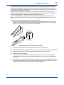
(1) Prepare a KCl solution available as an optional kit (part number: K9142UT), lf it is not yet
available, use instead KCl powder (about 12 g) and pure water (about 50 mL) and a clean
pipette (or a 20 mL syringe) to replenish the KCl solution.
KCl Powder
KCl Solution
Syringe
F3.1.ai
Figure 3.1
KCl Solution Replenishing Kit (Part Number: K9142UT)
(2) Remove the sensor from its holder. Wipe off dirty areas on the sensor tip.
(3) Remove the liquid junction from the sensor. Leave the indicator electrode mounted securely.
(4) Drain the KCl solution in the sensor through the liquid junction mounting hole.
(5) Wash the inside of the sensor
Pour about a 10 mL KCl solution (or pure Water) into the sensor from the liquid junction
mounting hole. Shake the sensor and then drain the solution or pure water completely from
the sensor.
(6) Pour about 10 or 12 grams of powder into the sensor, Use a bag of KCl powder when using
the optional KCl solution kit, Cut off the tip of the bag and follow Figure 3.2 below. If the KCl
powder has hardened, break it up into pieces. Then do the above.
IM 12C04K01-01E
< 3. Maintenance on operation >
Figure 3.2
3-3
Pouring KCl Powder into Sensor
(7) Pour the KCl solution (or pure water) into the sensor until it overflows through the junction
hole. In doing this, do not leave any air pockets in the body.
(8) Restore the liquid junction removed in Step (3) above to its original position.
3.2
Calibrate the sensor using buffer solutions.
Replacing Consumable Parts
3.2.1
Replacing Liquid Junction
Even after washing the liquid junction, if normal measurement cannot be made, replace the liquid
junction.
When replacing the liquid junction, fill the sensor with KCl solution to just before the solution
overflows through the liquid junction mounting hole. Use a 3.3 mol/L KCl solution (a higher
concentration of KCl or KCl powder) for this application.
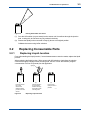
Syringe
(1)
Face the sensor
tip up and
remove the
defective liquid
junction from the
sensor.
Figure 3.4
(2)
Add KCl solution
to just before it
overflow through
the liquid junction
mounting hole.
(3)
Place a new
liquid junction in
position.
F3.4.ai
Replacing Liquid Junction
IM 12C04K01-01E
5th Edition : Nov.10,2015-00
3.2.2
< 3. Maintenance on operation >
3-4
Replacing O-rings for Indicator Electrode
As the inside of the indicator electrode mounting hole must have high insulation resistance,
fluorocarbon rubber O-rings - with superior chemical and heat resistance - are used for sealing.
Except for special uses, this O-ring does not need individual replacement. If any damage - which
might cause problems - is detected in the O-ring, as a rule, replace it along with the indicator
electrode.
Although the O-ring can be replaced individually if the O-ring deteriorates much faster than the
indicator electrode, it is recommended that the whole indicator electrode be replaced to avoid
possible deterioration of the O-ring inside the indicator electrode. For individual replacement of
the O-ring, use the one recommended by Yokogawa.
When installing the O-ring, wind a slip of paper or tape around the thread part on the indicator
electrode so as not to scratch the O-ring. Otherwise, such scratches may damage its sealing
properties.
For ordering, refer to the Customer Maintenance Parts List (CMPL) at the end of the book to
check the appropriate part number of the O-ring.
O-ring (Ø9/Ø12)
O-ring (Ø6/Ø9)
Screw
Before installing, wind a slip of paper or tape
around the thread part to prevent scratches.
Figure 3.5
Installing the O-ring
IM 12C04K01-01E
5th Edition : Nov.10,2015-00
Customer
Maintenance
Parts List
Model OR8ERG
KCl Refillable type ORP Sensor
Name Plate
Tip type
Pin type
RG
8E
OR
Ring type
1
2
Item
1
Part No.
Below
K9142TS
K9142TT
Qty
-
K9142QR
K9142QS
1
1
2
-
K9142TH
K9142QR
1
1
1
1
Description
ORP Electrode Assembly
Pt
Au
O-Ring, 6 mm ID X 9 mm OD
O-Ring, 9 mm ID X 12 mm OD
Junction Assembly
O-Ring, 6 mm ID X 9 mm OD
All Rights Reserved, Copyright © 1984, Yokogawa Electric Corporation.
Subject to change without notice.
CMPL 12C03K01-01E
3rd Edition : Apr. 2008 (YK)
i
Revision Information
: Model OR8ERG KCl Refillable type ORP Sensor
Title
Manual No. : IM 12C04K01-01E
Nov. 2015/5th Edition
Added FLXA202
P i, P1-2.
Unification ot the material name
P1-1.
Jun. 2013/4th Edition
P 1-3, Some revision of consumables, etc.
Sep. 2011/3rd Edition Page layout changed by InDesign
P.i, Reference manual number of FLXA21 added; P.v, Some of contents corrected; P.1-2, M4 ring
terminals for FLXA21 added to MS-code; P.1-3, M4 ring terminals added to external dimensions; P.
2-11, Section no. corrected (2.3.3--->2.3.4).
Apr. 2008/2nd Edition
M3 ring terminals added for PH450G, CMPL12C03K01-01E revised to 3rd edition.
Sep. 2006/1st Edition
Newly published.
n If you want to have more information about Yokogawa products, you can visit
Yokogawa’s home page at the following web site.
Home page: http://www.yokogawa.com/an
IM 12C04K01-01E
5th Edition : Nov.10,2015-00
Blank Page