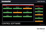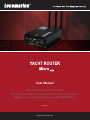
1
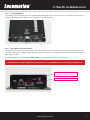
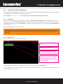
User Manual
Read carefully and DO NOT PANIC.
For better understanding check video tutorials on our website.
Register your product for software update notifications.
version 1.2
www.yachtrouter.com
1.
1.
2.
3.
4.
5.
6.
7.
8.
9.
10.
10.1.
10.2.
10.3.
10.4.
10.5.
10.6.
10.7.
11.
12.
12.1.
12.2.
12.3.
12.4.
13.
CONTENTS
COPYRIGHT NOTICE ........ 3
RoHS COMPLIANT ........ 3
INTRODUCING YACHT ROUTER SOLUTION
DISCLAIMER AND WARNING ........ 3
DECLARATION OF CONFORMITY ........ 3
SAFETY AND HAZARD ........ 4
SAFETY INSTRUCTION ........ 4
ABOUT YACHT ROUTER MICRO 4G ........ 5
FEATURES ........ 6
SPECIFICATIONS ........ 6
........ 3
WAN, LAN, Backbone networks ........ 6
Expanders and Extenders support ........ 6
Vessel-to-Shore WIFI ........ 6
Client-to-Vessel WIFI ........ 6
Mobile network ........ 7
Power, environment and dimensions ........ 7
Software features ........ 7
PACKAGING ........ 7
INSTALLATION INSTRUCTIONS
........ 8
Connecting WIFI and mobile network antennas ........ 8
Connecting power supply ........ 9
Inserting SIM card ........ 10
LED indicators and Service Port ........ 10
SETUP PROCEDURE
........ 11
13.1.
13.2.
13.3.
13.4.
13.5.
Installing Yacht Router 4G Control Software on computer with Windows operating system ........ 11
Installing Yacht Router 4G Control Software on your iPhone or iPad ........ 11
Installing Yacht Router 4G Control Software on your Android smart phone or tablet ........ 11
Connecting Touch Screen Controller 4G ........ 11
Power on Yacht Router ........ 12
14.1.
14.2.
14.3.
14.4.
14.5.
14.6.
14.7.
Initial screen ........ 13
Main screen ........ 13
SETUP screen ........ 15
Configuration screen ........ 16
Mobile WAN Networks setup ........ 17
Shore WIFI WAN Networks setup ........ 20
Vessel Network setup ........ 23
14.
15.
16.
17.
18.
19.
20.
Yacht Router 4G Control Software
........ 13
ONLINE REMOTE SUPPORT ........ 24
NETWORK DETAILS ........ 25
YACHT ROUTER CONFIGURATION TOOL ........ 26
LOCOMARINE LIMITED FACTORY WARRANTY ........
FCC INTERFERENCE STATEMENT ........ 26
INDUSTRY CANADA NOTICE TO USERS ........ 26
26
www.yachtrouter.com
2
1.COPYRIGHT NOTICE
Locomarine d.o.o. reserves the rights to alter the products described in this manual at any time without prior notice. This document
contains proprietary information protected by copyright. All rights are reserved. No part of this manual may be reproduced by any
mechanical, electronic, or other means in any form without prior written permission of the manufacturer. Information provided in
this manual is intended to be accurate and reliable. However, Locomarine d.o.o. assumes no responsibility for use of this manual,
nor for any infringements upon the rights of third parties, which may result from such use.
2.RoHS COMPLIANT
All models in the Yacht Router series comply with the Restriction of Hazardous Materials (RoHS) Directive. This means that all
components used to build Yacht Router are RoHS compliant. The RoHS Directive bans the placing on the EU market of new
electrical and electronic equipment containing more than agreed levels of lead, cadmium, mercury, hexavalent chromium,
polybrominated biphenyl (PBB) and polybrominated diphenyl ether (PBDE) flame retardants.
3.INTRODUCING YACHT ROUTER SOLUTION
Yacht Router is a complete network infrastructure solution for yacht or boat of any size. Yacht Router devices will help you to
easily install, setup and control Internet connection on your yacht. The most important part of Yacht Router solution is software
that control complete system. It is designed by professionals specialized in yacht communication systems in collaborations with
experienced yacht captains. The result is a system that is simple to operate, maintain and control. Underneath simple touch
user interface, Yacht Router is a solution with industry level of reliability, performance and unprecedented level of security.
4.DISCLAIMER AND WARNING
The contest of this manual are well prepared by Locomarine d.o.o.
While we try to improve our equipment at all time, Locomarine d.o.o. shall incur no liability based on contest, updates or
modification of the contest, or the lack of contents in this manual.
Because of the nature of wireless communications, transmission and reception of data can never be guaranteed. Data may be
delayed, corrupted (i.e., have errors) or be totally lost. Although significant delays or losses of data are rare when wireless devices
such as the Yacht Router are used in a normal manner with a well-constructed network, the Yacht Router device should not be
used in situations where failure to transmit or receive data could result in damage of any kind to the user or any other party,
including but not limited to personal injury, death, or loss of property. Locomarine d.o.o. and its affiliates accept no responsibility
for damages of any kind resulting from delays or errors in data transmitted or received using the Yacht Router device, or for failure
of the Yacht Router device to transmit or receive such data.
The equipment said in this manual must only be used to which it was designed.
Improper operation or installation may cause damages to the equipment or personal injury. Locomarine d.o.o. will not incur
any liability of equipment damage or personal injury due to improper use or installation of the equipment. It is strongly
recommended to read this manual and the following safety instructions before proceeding to installation or operation.
5.DECLARATION OF CONFORMITY
Hereby, Locomarine d.o.o. declares that this Yacht Router device is in compliance with the essential requirements and other
relevant provisions of Directive 1999/5/EC on R&TTE:
Article 3.2 (radio): ETSI EN 300 328 V1.7.1:2007
Article 3.1.b (EMC): ETSI EN 301 489-1 V1.9.2 (2011-09)
ETSI EN 301 489-17 V2.1.1 (2009-05)
Article 3.1.a (Safety): ETSI EN 60950-1:2006+A1:2010; EN 60950-22:2006
www.yachtrouter.com
3
6.SAFETY AND HAZARD
Do not operate your Yacht Router:
•
•
In areas where blasting is in progress.
Where explosive atmospheres may be present including refuelling points, fuel depots, and chemical plants, near medical
equipment, life support equipment, or any equipment which may be susceptible to any form of radio interference.
In such areas, the Yacht Router MUST BE POWERED OFF. Otherwise, the Yacht Router can transmit signals that could interfere
with this equipment. In an aircraft, the Yacht Router MUST BE POWERED OFF. Otherwise, the Yacht Router can transmit signals
that could interfere with various onboard systems and may be dangerous to the operation of the aircraft or disrupt the cellular
network. Use of a cellular and WIFI equipment in an aircraft is illegal in some jurisdictions. Failure to observe this instruction may
lead to suspension or denial of cellular services to the offender, or legal action or both.
IMPORTANT: Exposure to Radio Frequency Radiation.
20 cm minimum distance has to be maintained between the antenna (any) and the occupational user and 75 cm to general public.
7.SAFETY INSTRUCTION
ELECTRICAL SHOCK HAZARD: Do not open enclosure of the equipment if you are not qualified to do it.
TURN OFF THE POWER IMMEDIATELY IF WATER LEAKS INTO THE EQUIPMENT OR OBJECT DROPS INTO THE EQUIPMENT:
Continue operating the equipment could cause electrical shock or fire. Contact your nearest distributor or dealer for service.
DO NOT DISASSEMBLE THE EQUIPMENT OR MODIFY THE EQUIPMENT: Improper disassemble or modification could cause
electrical shock, fire, or personal injury.
AVOID OPERATING THE EQUIPMENT WITH WET HANDS: Electrical shocks could be resulted if operating with wet hands.
USE PROPER FUSE: Damage to the equipment or fire could be resulted if using improper fuse.
TURN OFF THE POWER IMMEDIATELY IF THE EQUIPMENT IS EMITTING SMOKE OR FIRE: Continue operating the equipment
could cause electrical shock or fire. Contact your nearest distributor or dealer for service.
DO NOT PLACE ANY LIQUID-FILLED CONTAINER ON TOP OF THE EQUIPMENT.
www.yachtrouter.com
4
8.ABOUT YACHT ROUTER MICRO 4G
Yacht Router Micro 4G is intended for installation on smaller boats and yachts without satellite Internet source (VSAT, Inmarsat,
Iridium etc). It will give you ability to establish single vessel WIFI network (Client-to-Vessel) that you will be able to connect to
other WIFI networks (e.g. marina WIFI Hotspots) or mobile networks (4G/3G/EDGE/GSM).
Schematic drawing of Yacht Router Micro 4G capability and connectivity.
www.yachtrouter.com
5
9.FEATURES
- ultra high power Vessel-to-Shore network (1600mW, b/g/n)
- high power 4G/3G/2G module (250-2000mW)
- 1x Client-to-Vessel WIFI network (b/g)
- 1x LAN port (100 Mbps)
- Online Remote Support
- wide range DC power input (9-18 V)
- wall mount aluminum enclosure
10.
SPECIFICATIONS
10.1.
WAN, LAN, Backbone networks
Ethernet WAN ports: not available
Ethernet LAN ports: 1
Backbone LAN ports: not available
Mobile Expander ports: not available
Max. data rate on WAN/LAN/Backbone (per port): 100 Mbps
10.2. Expanders and Extenders support
WIFI Extender support: no
PoE injector power outputs: not available
Mobile Expander support: no
LAN Expander support: no
Max. number of supported Mobile Expanders: not available
Max. number of supported LAN Expanders: not available
WIFI/LAN Expander DC power outputs: not available
10.3. Vessel-to-Shore WIFI
Internal WIFI module: yes
Remote WIFI module (PoE, outdoor): no
Supported standards: b/g/n
Max. data rates (Mbps): 100
Max. transmit power (dBm): 32
Max. transmit power (mW): 1600
Sensitivity of included antenna (dB): 5
Antenna connector type (on device): N-type female
10.4.
Client-to-Vessel WIFI
Max. number of networks: 1
Supported standards: b/g
Max. data rates (Mbps): 54
Max. transmit power (dBm): 20
Max. transmit power (mW): 100
Sensitivity of included antenna (dB): 5
Antenna connector type (on device): N-type female
www.yachtrouter.com
6
10.5. Mobile network
Integrated modems: 1
Europe/Africa/Asia/Oceania modem:
LTE freq. (MHz): 800 (B20), 900 (B8), 1800 (B3), 2100 (B1), 2600 (B7)
WCDMA freq. (MHz): 900 (B8), 2100 (B1)
GSM/GPRS/EDGE freq. (MHz): 900, 1800, 1900
Americas modem:
LTE freq. (MHz): 700 (B17), AWS (B4), 2100 (B1)
WCDMA freq. (MHz): 800 (B6), 850 (B5), 1900 (B2), 2100 (B1)
GSM/GPRS/EDGE freq. (MHz): 850, 900, 1800, 1900
Max. download rates (Mbps): 100
Max. upload rates (Mbps): 50
Max. transmit power in LTE/4G (dBm): 24
Max. transmit power LTE/4G (mW): 250
Max. transmit power in WCDMA (dBm): 24
Max. transmit power WCDMA (mW): 250
Max. transmit power in GSM/GPRS/EDGE (dBm): 33
Max. transmit power GSM/GPRS/EDGE (mW): 2000
SIM card slots: 1
SIM card size: standard GSM (ID-000)
Sensitivity of included antenna (dB): 2
Antenna connector type (on device): RP-SMA female
10.6.
Power, environment and dimensions
10.7.
Software features
11.
PACKAGING
DC power supply input range (V): 9-18
AC power supply input range (V): not available
Automatic switching AC-DC power controller: no
Max. power consumption (W, without WIFI Extenders): 17
Operating temperature range (°C): -10 to +60
Operating humidity range (%, non-condensing): 5-95
Enclosure material: aluminium
Enclosure mount type: wall
IP Protection: IP50
Dimension (mm, WxDxH, without antennas): 150 x 199 x 52
Hotspot: no
Hotspot supported on Client-to-Vessel WIFI networks: not available
WAN Auto-switching: no
Online Remote Support: yes
Selectable WAN source for each vessel network: yes
Detailed usage statistics: yes
Flexible assigning of LAN ports to vessel WIFI networks: no
Customizable WIFI power output: yes
Mobile Network Bonding: not available
Cloud Service: yes
Available remote user accounts for private access: 1
Number of on-board devices reachable through public access: 1
Number of on-board devices reachable through private access: unlimited
When shipped, all devices are wrapped in a plastic bags that protects it from humidity. Device is then placed into a cardboard box.
A bag containing accessory items is placed inside the box too. List of included accessories is included in the package.
www.yachtrouter.com
7
12.
INSTALLATION INSTRUCTIONS
Install Yacht Router Micro 4G in a dry indoor space that will meet Operating environment range specifications (chapter 9.6).
Follow the installation procedure as specified in this chapter.
WARNING: Exposure to Radio Frequency Radiation!
20 cm minimum distance has to be maintained between the antenna (any) and the occupational user and 75 cm to general
public.
12.1. Connecting WIFI and mobile network antennas
WARNING: NEVER POWER ON YACHT ROUTER IF MOBILE NETWORK ANTENNA IS NOT CONNECTED TO YACHT ROUTER
TO AVOID SEVERE DAMAGES ON MOBILE NETWORK MODULE THAT CAN VOID THE WARRANTY.
Connect WIFI and mobile antennas as showed on the following photo:
Locomarine WIFI 5 antenna
(swivel, indoor) - WLAN-A-05
Locomarine MOB 5 antenna
(swivel, indoor) - 3G-A-01
WIFI antenna extension cable 1m - WLEC-01
IMPORTANT: Never place antennas in the same horizontal level. If you cannot avoid that position, minimum horizontal
distance between antennas should be 1 meter. If you do not follow that rule, strong interference on both antennas could
occur that could significantly degrade data traffic, transmitting and receiving performance. NEVER CONNECT BOTH WIFI
ANTENNAS DIRECTLY TO YACHT ROUTER. Use WIFI antenna extension cables supplied with your system.
www.yachtrouter.com
8
When internal antennas does not give satisfied connectivity we suggest installation of external WIFI antenna that will increase
range and performance in vessel-to-shore connectivity (e.g. Hotspot in marina). We suggest the same for mobile network antenna
too. If you plan to install external antennas use only high-quality antennas and low-less coax cables to avoid signal degradation
(check our website www.yachtrouter.com).
Example of External WIFI and Mobile antennas with various
mounts connected via coax cables to Yacht Router.
SCAN UHF3G3B3 mobile network antenna
Deck mount
Adaptor tube
RP-SMA male to N-type female adaptor - RTN-01
12.2. Connecting power supply
Yacht Router Micro 4G has wide range DC power supply (9-18 VDC). We strongly suggest you to install proper fuses (2.5A) on
power supply sources cable (positive - red cable). Connect power cable that is supplied with Yacht Router where RED is positive
and BLACK cable is negative (ground).
WARNING: WRONGLY CONNECTED DC POWER CABLE CAN DESTROY YACHT ROUTER THAT CAN VOID THE WARRANTY.
PROVIDE SUFFICIENT POWER SUPPLY. INSUFFICIENT POWER SUPPLY WILL REPEATEDLY RESET AND DAMAGE YACHT
ROUTER THAT CAN VOID THE WARRANTY.
www.yachtrouter.com
9
12.3. Inserting SIM card
Yacht Router Micro 4G will work with any Standard GSM (ID-000) SIM card. If you have micro or nano SIM card you will have to
obtain proper adaptor. Insert SIM card as it is showed on the following photo:
12.4. LED indicators and Service Port
Yacht Router Micro 4G has two LED indicators. Blue LED indicate that device is powered on. Green LED indicate boot process.
Yacht Router Micro 4G is equipped with single Ethernet ports. Ethernet port is equipped with green and yellow LED indicator for
data traffic indication.
Yacht Router Micro 4G is equipped with SERVICE PORT. It is intended for diagnostic and programming.
WARNING: DO NOT CONNECT AND DEVICE TO SERVICE PORT AS IT CAN DAMAGE YACHT ROUTER AND VOID WARRANTY.
Blue LED - power indication
Green LED - boot indication
Service Port - DO NOT USE!
www.yachtrouter.com
10
13.
SETUP PROCEDURE
Once you finished installation you should proceed to setup procedure as specified in this chapter. You can control Yacht Router via
computer with Windows OS, iPhone, iPad or Android smart phone or tablet. You can simultaneously use multiple and different
platforms (e.g. iPhone, Android and PC) to control Yacht Router. If your system is equipped with Touch Screen Controller 4G check
Chapter 12.4.
13.1. Installing Yacht Router 4G Control Software on computer with Windows operating system
Every Yacht Router is supplied with USB memory stick. On a stick you can find Yacht Router 4G Control Software installation
software. Double click on YachtRouterSetup and computer will start with installation. During installation, computer will ask
you following question: “Do you want to allow the following program from an unknown publisher to make changes to your
computer?”. Click on “Yes” and proceed with installation.
YR Control Software is developed for Microsoft Windows 7 and Windows 8 operating system but if will probably work on Vista and
XP. Locomarine does not offer support for any Yacht Router system that is not installed on Windows 7 or Windows 8 operating
system.
We strongly suggest you to download latest version of Yacht Router 4G Control Software from Yacht Router website and subscribe
to Software Update Notification Newsletter on our website www.yachtrouter.com.
IMPORTANT: Yacht Router 4G Control Software will not work correctly if Microsoft Internet Explorer 10 and Microsoft
.NET Framework 4 is not installed on your computer. You can download Internet Explorer 10 from a following link:
http://windows.microsoft.com/en-us/internet-explorer/ie-10-worldwide-languages
You can download Microsoft .NET Framework 4 from a following link:
http://www.microsoft.com/en-us/download/details.aspx?id=17851
We strongly suggest you to perform latest update of your Windows operating system.
13.2. Installing Yacht Router 4G Control Software on your iPhone or iPad
To install Yacht Router 4G Control Software go to Apple AppStore. Use it the same way as it is described in this manual.
13.3. Installing Yacht Router 4G Control Software on your Android smart phone or tablet
To install Yacht Router 4G Control Software go to Google PlayStore. Use it the same way as it is described in this manual.
13.4. Connecting Touch Screen Controller 4G
Touch Screen Controller 4G is small size panel mount computer with embedded Yacht Router 4G Control Software. It is equipped
with touch screen and is more robust than standard computers and tablets. To connect it to Yacht Router plug supplied (or similar)
Ethernet cable to LAN or BACKBONE port on Yacht Router. Connect power supply to Touch Screen Controller 4G and turn it ON.
Touch Screen Controller 4G will automatically connect to Yacht Router.
www.yachtrouter.com
11
13.5. Power on Yacht Router
Once you installed Yacht Router 4G Control Software or connected Touch Screen Controller 4G you can power on Yacht Router.
After you turn in on, power LED indicator will light up and you will hear few beeps from Yacht Router. After about half a minute
of boot period Yacht Router is ready for use. You will know it is ready once you can find Vessel Network 1, Vessel Network 2 and
Vessel Network 3 wireless network after network scan on your computer, iPhone, iPad or Android device. Connect your device to
Vessel Network 1, Vessel Network 2 or Vessel Network 3 wireless network.
Initial password for Vessel Network 1, Vessel Network 2 or Vessel Network 3 wireless network is: 12345678
IMPORTANT: Be sure your computer is connected only to WIFI Vessel Network. Disconnect all other connections (e.g.
LAN). Check that the computer is set to obtain IP address automatically (DHCP enabled). On the following link you can
find instructions how to do that:
http://windows.microsoft.com/en-US/windows7/Change-TCP-IP-settings
www.yachtrouter.com
12
14.
Yacht Router 4G Control Software
Yacht Router 4G Control Software is simple and easy to use. All platform versions (Windows OS, iOS, Android) has same features
and software will automatically adopt to different screen sizes.
On our website www.yachtrouter.com under Support menu you can find very useful Video Tutorials.
14.1. Initial screen
Once you start Yacht Router 4G Control Software you will see Connected to Yacht Router and button Enter in green colour. In
upper right corner you will see Contact Us button that will give you Locomarine Support contacts. If your device is not able to
connect to Yacht Router you will see Connecting... message. Check if your device is properly connected to Vessel Network 1
wireless network.
Press green Enter button to enter main screen.
IMPORTANT: Every time you see small clock indicator in upper red status bar you should wait for Yacht Router to finish
requested process. It small clock is present in the status bar, control software will not accept any new request from
client side.
14.2. Main screen
On a Main screen you will see following informations:
LOCK - locking Yacht Router 4G Control
Software
SETUP - enter setup screen.
Vessel network name. Initial name is
Vessel Network 1 but you can change it.
Green button shows where is Vessel
Network 1 currently connected. Initial
value is Shore WIFI. You will use this
button to change Internet source (WAN)
for Vessel Network 1.
Yacht Router Micro 4G has one vessel network. Default name for this network is Vessel Network 1.
You can change this name and we suggest you to change it (e.g. Sea Dragon Network 1) to avoid situation when another vessel
with Yacht Router is in a vicinity.
www.yachtrouter.com
13
Shore WIFI, Inmarsat FleetBroadband and 4G Mobile buttons can be represented in three different colours.
Each colour has different meaning:
GREEN - Internet is available
YELLOW - Internet is not available
RED - WAN is disabled
If you press Shore WIFI button under Vessel Network 1 drop-down menu will appear. In that manu you can change your Internet
source (WAN) for Vessel Network 1. You will do the same for all Vessel Networks. Each Vessel Network can simultaneously be
connected to a different WAN source. It means that all devices (computers, smart phones, cameras etc) connected to Vessel
Network 1 can reach Internet, for example, via VSAT satellite connection while in the same time all devices connected to Vessel
Network 2 can use WIFI connection via Hotspot in marina to reach the Internet and all devices connected to Vessel Network 3
can go to the Internet via 4G mobile network. On upper example (screenshot) Vessel Network 1 is connected to the Internet via
Shore WIFI, Vessel Network 2 via Inmarsat FleetBroadband and all other Vessel Networks via 4G Mobile.
But, before you start using Internet source selection you must setup your connections and other important values. To open Setup
screen press SETUP button in upper right corner of Main screen.
www.yachtrouter.com
14
14.3. SETUP screen
Setup screen is divided in three sections. Each section is dedicated to different setup and consist of:
Internet sources (WAN) section
Mobile Wan Networks button
Default value: 4G Mobile (changeable) Description: open Mobile Wan Network setup screen.
Shore WIFI Wan Networks button
Default value: Shore WIFI (changeable)
Description: open Mobile Wan Network setup screen
Vessel Networks section
Vessel Network 1 button
Default value: Vessel Network 1 (changeable)
Description: open Mobile Wan Network setup screen.
General Setup section
Configurations button
Description: open Configuration setup screen.
Contact Us button
Description: open Contact Us screen with Locomarine contact details.
Support Network button
Description: open Support Network connections menu. To use this feature Yacht Router must be connected to
Internet. You will use this feature if you need support from our Technical support. Please read section REMOTE
SUPPORT chapter for remote support request procedure.
BACK - back to Main menu
General Setup section
Vessel Networks section
Internet source (WAN) section:
Mobile WAN Networks button
Shore WIFI Wan Networks button
First value you should setup is Yacht Router Lock Password.
IMPORTANT: Set your Lock Password! If you do not set it anyone who is connected to any Vessel Network (WIFI or
LAN) with installed Yacht Router 4G Control Software on any of supported device will be able to control Yacht Router.
It can cause many unwanted and very expensive consequences (e.g. if someone switch Internet source on your Vessel
Network from WIFI Hotspot in marina to your Inmarsat FleetBroadband while you are watching movie on YouTube).
To setup Lock Password press Configurations button to open Configurations screen.
www.yachtrouter.com
15
14.4. Configuration screen
Setup screen is divided in three sections:
Global Settings section
Reset to Factory Default button
Description: open menu to Confirm that you want to reset to factory defaults.
Revert To Saved Configuration button
Description: open menu to Confirm that you want to revert to saved configuration.
Save Current Configuration button
Description: open menu to Confirm that you want to revert to save current configuration.
WIFI Extenders settings
WIFI Extenders are not supported by Yacht Router Micro.
Other Settings section is consist of:
Lock Password field
Description: Yacht Router Lock Password that will prevent other people to setup. Press UPDATE button to enter value.
Vessel to Shore WIFI Power field
Default value: 0 (changeable) Description: enter transmit power of Vessel-to-Shore WIFI module to obey your country regulations. Default value
is 0 and it will set transmit power to maximum available for your Yacht Router. Press UPDATE button to enter value.
UPDATE button
Description: update value entered in Lock Pasword and WIFI Power fields.
BACK - back to Setup menu
Other Settings section - Lock Password
and WIFI Power fields
WIFI Extenders section - WIFI Extenders
are not supported by Yacht Router Micro
Global Settings section
Enter password in Lock Password field and press UPDATE button. Your Yacht Router is now protected with a password. From now
on, every time you start Yacht Router 4G Control Software on any supported device (computer, iPhone, iPad, Android) you will be
prompted to enter password on Initial screen. Once your enter correct password Enter button will become green.
You can proceed to further setup.
www.yachtrouter.com
16
14.5. Mobile WAN Networks setup
Once you press Mobile WAN Networks button on Setup screen you will open WAN Network setup screen that consist of:
Main section
WAN Name field
Default value: 4G Mobile (changeable)
Description: enter name of your Mobile connection (e.g. Vodafone Greece).
WAN Status button
Description: turn on or off modem. Once turned off it will take up to one minute to turn back on.
Internet button
Description: show Internet connectivity status (Available or Unavailable). Click on button to refresh status.
OK button
Description: once you made changes in WAN Name field click on OK button to confirm changes.
Mobile Status section
APN field
Description: APN is data provided by your SIM card provider. It is necessary for Internet connection.
PIN field
Description: PIN data protect your SIM card and it is provided with your SIM card.
More Options button
Description: open menu with addition setup buttons and fields.
Auto LTE 3G GSM buttons
Default: Auto (changeable)
Description: Mobile connection technology. Auto = fastest available technology (LTE-3G-GSM).
Username field
Description: some mobile network providers use username data. It should be provided with SIM card.
Password field
Description: some mobile network providers use password data. It should be provided with SIM card.
Modem Init field
Description: some mobile network providers use Init data. It should be provided with SIM card.
Roaming button
Description: enable or disable roaming.
ADVANCED - open Advanced features
BACK - back to Setup menu
WAN Name - enter name for your
Mobile network source
WAN Status - turn on/off modem for
Mobile network connection
APN and PIN- Access Point Name and
PIN are provided with your SIM card
More Options - additional setup
Username, Password and Modem Init used by some Mobile providers
Connection technology setup - you can setup Yacht
Router to use different mobile connection technology
www.yachtrouter.com
Roaming - enable or disable roaming
17
If you press ADVANCED button in upper right corner you will get access to advanced setup and info.
WAN IP Address configuration section
DHCP buttons
Default value: On (changeable)
Description: enabling or disabling DHCP (Dynamic Host Configuration Protocol), Renew button will renew settings
when DHCP is enabled, Refresh button refresh data in IP, SUBNET, GATEWAY, DNS 1, DNS2 fields.
IP field
Default value: not defined (changeable)
Description: show IP (Internet Protocol) address.
SUBNET field
Default value: not defined (changeable)
Description: show logically visible subdivision of an IP network.
GATEWAY field
Default value: not defined (changeable)
Description: a node on a TCP/IP network that serves as an access point to another network.
DNS 1 & DNS 2 fields
Default value: not defined (changeable)
Description: server that hosts a network service for providing responses to queries against a directory service.
UPDATE STATIC CONFIG button
Description: update manually entered data (IP, SUBNET, GATEWAY, DNS 1, DNS2) when DHCP is set to off.
Traffic Info section
Description: show information about data traffic since Yacht Router is powered on for the last time.
ADVANCED -open WAN IP Address configuration and Trafic Info section
Trafic Info section - data traffic info
DHCP setup - you can turn it on/off,
Renew IP and Refresh data
WAN IP Address configuration section
www.yachtrouter.com
18
To check Mobile Network status and connectivity details click on gray field/button as specified on the following picture. You will
get following information: PIN Status, Functionality, Current Operator, Signal Strength, Access Technology, IMEI.
Click here to get precise data about
mobile network and connectivity
status.
Mobile Status - indicate current connection status. It is a combination of information taken from Current Operator field
and Access Technology field described bellow.
call in progress <Current Operator> <mobile network name>: indicate that Yacht Router is connected to the mobile
network and Internet is available. For example: call in progress TELE2 3G means that you are connected to TELE2
mobile network using 3G technology and that Internet is available.
ready <mobile network name>: indicate that Yacht Router is connected to the mobile network but WAN is disabled
and Internet is not available.
ERROR: SIM not inserted: indicate that SIM card is not inserted or recognised by Yacht Router, it often indicate that
SIM card is damaged.
PIN Status - information about SIM card PIN protection.
no password required: indicate that PIN code in not enabled on SIM card currently in use.
waiting for primary PIN: indicate that PIN code for SIM card currently in use is not correct or not entered at all.
Functionality - indicated current connection functionality.
minimum: indicate that you have full connection functionality. The reasons can be various, from damaged SIM card,
wrong PIN, low signal strength etc.
full: indicate that you have full connection functionality.
Current Operator - current operator name or limited service indication.
<mobile network name>: name of mobile network currently in use.
Limited Service <mobile network name>: indicate that you are connected to the mobile network but your access to
the Internet is limited. Reasons can be various: your subscription is out of date or you do not have any more credits on
your account. Maybe you have to activate your SIM card over the Internet or mobile phone before first use. Or maybe
your data plan does not allow connection to the Internet using Access Technology that you have selected - some
providers require additional subscription for LTE technology. The easiest solution to find out why your access to the
Internet is limited is to contact your mobile provider. One of the reason can also be damaged SIM card.
Signal Strength - mobile network signal strength in dBm.
Access Technology - currently used access technology.
GSM compact: GPRS and EDGE with data rate up to 350 kbps
3G: HSUPA/HSDPA/HSPA+ with data rate up to 42 Mbps
LTE: sometimes called 4G with data rate up to 100 Mbps
IMEI - International Mobile Equipment Identity; number that indicate modem used for mobile network connectivity.
Some mobile providers ask for IMEI number.
www.yachtrouter.com
19
14.6.
Shore WIFI WAN Networks setup
Once you press Shore WIFI WAN Networks button on Setup screen you will open WAN Network setup screen that consist of:
Main section
WAN Name field
Default value: Shore WIFI (changeable)
Description: enter name of your Ship-to-Shore connection (e.g. Marina Hotspot).
WAN Status button
Description: turn on or off connection to Shore WIFI.
Internet button
Description: show Internet connectivity status (Available or Unavailable). Click on button to refresh status.
OK button
Description: once you made changes in WAN Name field click on OK button to confirm changes.
WIFI Status section
WIFI Network field
Default value: not defined (changeable)
Description: show name of currently connected WIFI network. You can enter it manually if you want. Once you enter
it enter password (for encrypted WIFI networks) and press Connect to WIFI button to connect.
Password field
Default value: not defined (changeable)
Description: enter password to connect to encrypted WIFI networks. Yacht Router can connect to WIFI networks with
following encryption protocols: WPA/WPA2, EAS/TKIP, WEP (limited).
Use WEP button
Default value: Off (changeable)
Description: turn it on if you plan to connect to WIFI network with WEP encryption.
Note: As WEP encryption is not really secure, Yacht Router support only WEP with Static Key Optional 40 bit
Start Scanning button
Description: scan for available networks. List of available networks with appear with signal strength info (signal to
noise ratio in dB) and three colour codes: green=OK, red=poor. To connect to WIFI network click on a button with
network name. Chosen WIFI network name will appear in WIFI Network field. Enter Password if network is encrypted
end press Connect to WIFI button to connect.
Connect to WIFI button
Description: click on button to connect to WIFI network.
WAN Name - enter name for your
Shore WIFI network source
WAN Status - turn on/off connection
to Shore WIFI network
WIFI Network - name of currently
connected Shore WIFI network
Use WEP - enable connectivity to WEP
protected WIFI networks
Start Scanning - scan for available
WIFI networks
List of available WIFI networks with
signal strength info
www.yachtrouter.com
20
If you press ADVANCED button in upper right corner you will get access to advanced setup and info.
WAN IP Address configuration section
DHCP buttons
Default value: On (changeable)
Description: enabling or disabling DHCP (Dynamic Host Configuration Protocol), Renew button will renew settings
when DHCP is enabled, Refresh button refresh data in IP, SUBNET, GATEWAY, DNS 1, DNS2 fields.
IP field
Default value: not defined (changeable)
Description: show IP (Internet Protocol) address.
SUBNET field
Default value: not defined (changeable)
Description: show logically visible subdivision of an IP network.
GATEWAY field
Default value: not defined (changeable)
Description: a node on a TCP/IP network that serves as an access point to another network.
DNS 1 & DNS 2 fields
Default value: not defined (changeable)
Description: server that hosts a network service for providing responses to queries against a directory service.
UPDATE STATIC CONFIG button
Description: update manually entered data (IP, SUBNET, GATEWAY, DNS 1, DNS2) when DHCP is set to off.
Traffic Info section
Description: show information about data traffic since Yacht Router is powered on for the last time.
ADVANCED -open WAN IP Address configuration and Trafic Info section
Trafic Info section - data traffic info
DHCP setup - you can turn it on/off,
Renew IP and Refresh data
WAN IP Address configuration section
www.yachtrouter.com
21
To check Shore WIFI Network status and connectivity details click on gray field/button as specified on the following picture.
Click here to get precise data about
mobile network and connectivity
status.
You will get following statuses: ssid, band, frequency, wireless protocol, tx rate, rx rate, bssid, signal strength, tx signal strength,
noise floor, signal to noise ratio, tx ccq, rx ccq, overall tx ccq, last ip, authentication-type, group encryption, management
protection, compression.
ssid - Service Set Identifier is name of WIFI network.
band - frequency band of WIFI network currently in use.
2ghz-b: with data rate up to 2 Mbps
2ghz-g: with data rate up to 11 Mbps
2ghz-n: with data rate up to 54 Mbps
frequency - WIFI frequency expressed in Hz.
wireless protocol - WIFI protocol on WIFI network currently in use.
tx-rate - maximum transmit data rate for current WIFI connection.
rx-rate - maximum receive data rate for current WIFI connection.
bssid - Basic Service Set Identifier is unique address (name) that identifies the access point/router that creates the
wireless network.
radio name - MT proprietary extension for Atheros cards.
signal strength - WIFI signal strength in dBm
tx signal strength - transmit signal level in dBm
noise floor - noise level in dBm.
signal to noise - difference between signal strength and noise floor. This is the best indicator of WIFI signal quality. Higher
value means better signal. For example, if signal strength is -10 dBm and noise floor is -107 dBm than signal to noise is 97
dB. This number actually shows you how much your WIFI signal is stronger than noise.
more than 40 dB: excellent signal
25-40 dB: very good signal
15-25 dB: low signal
10-15 dB: very low signal
less than 10 dB: no signal
tx-ccq - Client Connection Quality is value in percent that shows how effective the transmit bandwidth is used regarding
the theoretically maximum available bandwidth.
rx-ccq - Client Connection Quality is value in percent that shows how effective the receive bandwidth is used regarding
the theoretically maximum available bandwidth.
overall tx ccq - overall Client Connection Quality is value in percent that shows how effective the transmit bandwidth is
used regarding the theoretically maximum available bandwidth.
last ip - IP address found in the last IP packet received from the registered client.
authentication type - authentication method used by current WIFI network.
group encryption - encryption algorithm used by current WIFI network.
management protection - status of management protection authentication mode.
compression - status of hardware compression on current WIFI network.
www.yachtrouter.com
22
14.7.
Vessel Network setup
Once you press Vessel Network 1 button on Setup screen you will open Vessel Network setup screen that consist of:
Main section
Name field
Default value on Vessel Network 1: Vessel Network 1 (changeable)
Description: enter name of Vessel Network 1. This name will appear in Main Screen menus.
WIFI SSID field
Default value on Vessel Network 1: Vessel Network 1 (changeable)
Description: enter name of WIFI component of your Vessel Network. This name will appear on all devices during WIFI
scanning (e.g. Sea Dragon WIFI during WIFI scan with your laptop).
WIFI Password field
Default value on Vessel Network 1: 12345678 (changeable)
Description: enter password for WIFI Vessel Network.
ADVANCED -open DHCP Client List
section
Name - enter your vessel network name
that will appear on Main screen
WIFI SSID - enter name that will your
vessel network transmit as WIFI
DHCP Client List section - list of currently connected DHCP clients
Make Static - fix static IP to conected
clients
If you press ADVANCED button in upper right corner DHCP Client List section will appear. It will show list of currently connected
clients (devices) with their MAC (Media Access Control) and IP address. If you click on any client it will open additional buttons:
DHCP Client List section
Make Static button
Description: fix listed DHCP client to static IP address.
Delete button
Description: delete DHCP client from DHCP list.
www.yachtrouter.com
23
15.
ONLINE REMOTE SUPPORT
Each Yacht Router is equipped with Online Remote Support feature that gives our technical support ability to connect to your
Yacht Router to check and resolve possible problems.
To establish Online Remote Support you have to send an e-mail to [email protected] with following details:
1. Contact details (Name, e-mail, phone number)
2. Yacht Router model (Micro, Mini, Standard, Pro)
3. Yacht Router serial number.
4. Description of the problem.
5. Suggested best time (minimum one) when our technicians can connect to your Yacht Router. Please note that our Support Team
is available from Monday to Friday, 9-17 hrs (Central European Time).
Once we receive your request we will provide further instructions by e-mail or phone.
IMPORTANT: to establish Remote support Vessel Network 1 on your Yacht Router MUST be connected to the Internet.
To perform additional diagnostics our Support Team will sometimes need to connects remotely to your computer. To do that you
will have to install Team Viewer software. If you already use this software you will have to provide Your ID and Password from
Team Viewer software. You can fine Team Viewer download link on our website www.yachtrouter.com under Support section or
simply click here.
www.yachtrouter.com
24
16.
NETWORK DETAILS
Yacht Router Micro 4G has reserved IP ranges that cannot be used by other connected equipment:
Support network: 10.10.0.0/16
Reserved range: 10.80.0.0/12
Yacht Router Micro 4G IP reservation details
Backbone Network: 10.81.0.1/16
Vessel Network 1:
Gateway: 10.81.0.1
Free static range: 10.81.0.3 - 10.81.0.99
DHCP: 10.81.0.100 - 10.81.255.254
DNS: 10.81.0.1, 8.8.8.8
VLAN id usage: 1-9
www.yachtrouter.com
25
17.
YACHT ROUTER CONFIGURATION TOOL
Yacht Router Configuration Tool is a software that will give you ability to assign each VESSEL NETWORK Ethernet port to Vessel
Network of your choice. BACKBONE and SAT ports cannot be reconfigured.
To obtain the software contact us on [email protected]
18.
LOCOMARINE LIMITED FACTORY WARRANTY
Locomarine manufactures marine electronic products which are marketed and supported worldwide via the Locomarine
distributor, dealer and partner network. Each and every Locomarine distributor, dealer and partner is committed to service and
support the products in accordance with the market’s needs and requirements. In addition, the Locomarine distributor, dealer
and partner networks are obliged to support the products irrespective of who sold and installed the product.
Locomarine Limited Factory Warranty for Yacht Router products can be downloaded from www.yachtrouter.com under Support/
Download section.
19.
FCC INTERFERENCE STATEMENT
This equipment has not been tested and not found to comply with the limits for a Class B digital device, pursuant to Part 15 of the
FCC Rules. These limits are designed to provide reasonable protection against harmful interference in a residential installation.
This equipment generates, uses and can radiate radio frequency energy and, if not installed and used in accordance with the
instructions, may cause harmful interference to radio communications. However, there is no guarantee that interference will not
occur in a particular installation. If this equipment does cause harmful interference to radio or television reception, which can be
determined by turning the equipment off and on, the user is encouraged to try to correct the interference by one of the following
measures:
• Reorient or relocate the receiving antenna.
• Increase the separation between the equipment and receiver.
• Connect the equipment into an outlet on a circuit different from that to which the receiver is connected.
• Consult the dealer or an experienced radio/TV technician for help.
FCC Caution: Any changes or modifications not expressly approved by the party responsible for compliance could void the user’s
authority to operate this equipment.
This device may complies with Part 15 of the FCC Rules. Operation is subject to the following two conditions: (1) This device may
not cause harmful interference, and (2) this device must accept any interference received, including interference that may cause
undesired operation.
This device and its antenna must not be co-located or operation in conjunction with any other antenna or transmitter.
IMPORTANT: Exposure to Radio Frequency Radiation.
20 cm minimum distance has to be maintained between the antenna (any) and the occupational user and 75 cm to general public.
Under such configuration, the FCC radiation exposure limits set forth for an population/uncontrolled environment can be satisfied.
20.
INDUSTRY CANADA NOTICE TO USERS
Notice: To satisfy IC RF exposure requirements for mobile and base station transmission devices, a separation distance of 20 cm or
more should be maintained between the antenna of this device and persons during operation. To ensure compliance, operation
at closer than this distance is not recommended. The antenna(s) used for this transmitter must not be co-located or operating in
conjunction with any other antenna or transmitter.
Avis: Pour répondre à la IC d’exposition pour les besoins de base et mobiles dispositifs de transmission de la station, sur une
distance de séparation de 20 cm ou plus doit être maintenue entre l’antenne de cet appareil et les personnes en cours de
fonctionnement. Pour assurer le respect, l’exploitation de plus près à cette distance n’est pas recommandée. L’antenne (s) utilisé
pour cet émetteur ne doit pas être co-localisés ou fonctionner conjointement avec une autre antenne ou transmetteur.
www.yachtrouter.com
26