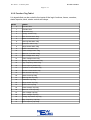
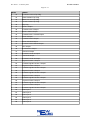
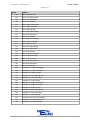
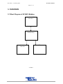
1
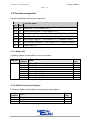
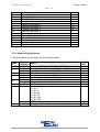
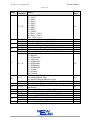
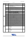
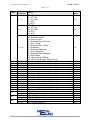
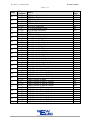
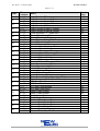
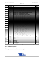
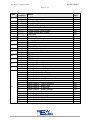
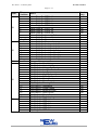
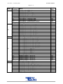
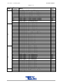
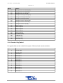
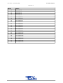
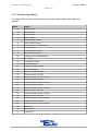
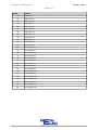
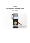
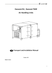
NC-MK1-Modbus
Rev 1B-01 – 21 January 2014
Page 1 / 31
NewCode
Modbus
Communication Module
User Manual
NC-MK1-Modbus
Version 1A-01
(NE_NC-MK1-Modbus_MAN_01_14_A-01)
13 January 2014
NC-MK1-Modbus
Rev 1B-01 – 21 January 2014
Page 2 / 31
Content
Page
1. ABSTRACT ........................................................................................................................... 4
2. SPECIFICATIONS................................................................................................................. 5
2.1 Technical Specifications of NC-MK1-Modbus................................................................ 5
2.2 Functions supported ......................................................................................................... 6
2.2.1 Read Coils ................................................................................................................. 6
2.2.2 Read Discrete Input Register..................................................................................... 6
2.2.3 Read Holding Registers............................................................................................. 7
2.2.4 Read Input Registers ............................................................................................... 13
2.3 Listen mode only............................................................................................................ 20
2.2.5 Function Flag Table 1.............................................................................................. 21
2.2.6 Function Flag Table 2.............................................................................................. 25
2.2.7 Function Flag Table 3.............................................................................................. 27
3. DEFINITIONS AND TERMINOLOGY ............................................................................. 29
4. OPERATING INSTRUCTIONS.......................................................................................... 30
4.1 Getting Started................................................................................................................ 30
4.1.1 Setting Up The NC-MK1-Modbus.......................................................................... 30
4.2 Monitoring Diagnostic On Front-End ............................................................................ 30
4.3 DB 9 Connection ............................................................................................................ 30
4.4 Synchronizing The RTC................................................................................................. 30
5. DIAGRAMS......................................................................................................................... 31
5.1 Block Diagram of NC-MK1-Modbus ............................................................................ 31
NC-MK1-Modbus
Rev 1B-01 – 21 January 2014
Page 3 / 31
Date
13 Jan 2014
Revision
1A-01
16 Jan 2014
1B-01
Revision History
Description
-Draft submitted for review.
-Draft released to CD.
-Corrected logic maps.
-Added change of RTC global.
NC-MK1-Modbus
Rev 1B-01 – 21 January 2014
Page 4 / 31
1. ABSTRACT
The NC-MK1-Modbus (NewCode Modbus) acts as a translator between the Modbus
SCADA and the NewCode. It is advisable to read the NewCode user manual, as
some of the topics will require knowledge on the NewCode. It is also advisable to
have knowledge on Modbus. Modbus specification document can be found on the
web from http://www.modbus.org/.
The communication protocol between the NC-MK1-Modbus and SCADA is ModbusRTU. Communication protocol between the NC-MK1-Modbus and the NewCode is a
NewElec proprietary protocol. Enabling the PLC to communicate with the NewCode
via Modbus.
NC-MK1-Modbus
Rev 1B-01 – 21 January 2014
Page 5 / 31
2. SPECIFICATIONS
2.1 Technical Specifications of NC-MK1-Modbus
General Data
NC-MK1Modbus
Mounting Positions
Allowed Ambient
Temperature
Humidity
Power Supply
Consumption
Communication Mediums
Protocol
Baud Rate
Modbus
Cable Length @ Baud Rate
Termination Resistor
(Termination resistors must
be connected at the
beginning and end of bus)
Type
LED Indications
Indication
Lights
Mounted inside of NewCode.
Operation : 0 ºC to +60 ºC
< 87%
+5Vdc
20 mA
Modbus
I2C
Modbus-RTU
2400 bit/s
4800 bit/s
9600 bit/s
19200 bit/s
38400 bit/s
57600 bit/s
1200 m @ 2400 bit/s to 38400
bit/s
1000 m @57.6Kbit/s
150 Ohm ( 0.5W ).
Light Emitting Diode (LED)
SCADA Communication
◦ Red = No communication.
◦ Green = Receiving.
Address Of Module
◦ Green Flash = 1
◦ Red Flash = 10
◦ Orange Flash = 100
◦ Red Solid = I2C Error
◦ Orange Solid = Modbus Error
NC-MK1-Modbus
Rev 1B-01 – 21 January 2014
Page 6 / 31
2.2 Functions supported
Following Modbus functions are supported:
Function
Hex
Function Name
Dec
0x01 01
Read Coils. ( See Chapter 2.2.1 )
0x02 02
Read Discrete Inputs. ( See Chapter 2.2.2 )
0x03 03
Read Holding Registers. ( See Chapter 2.2.3 ) (Address 0x4000)
0x04 04
Read Input Registers. ( See Chapter 2.2.4 ) (Address 0x3000)
0x06 06
Write Single Register. ( See Chapter 2.2.3 ) (Address 0x4000)
0x10 16
Write Multiple Registers. ( See Chapter 2.2.3 ) (Address 0x4000)
0x11 17
Report Slave ID.
2.2.1 Read Coils
Following values can be read from the coil register:
Address
0
Bit
Position
0
1
2
3
4
5
6
7
Read
Only
Yes
Yes
Yes
Yes
Yes
Yes
Yes
Yes
Name
Relay 1 Status
Relay 2 Status
Relay 3 Status
Relay 4 Status
External Relay 5 Status
External Relay 6 Status
External Relay 7 Status
External Relay 8 Status
2.2.2 Read Discrete Input Register
Following values can be read from the discrete input register:
Input
Position
0
1
2
Name
Field Input 1
Field Input 2
Field Input 3
Read
Only
Yes
Yes
Yes
NC-MK1-Modbus
Rev 1B-01 – 21 January 2014
Page 7 / 31
3
4
5
6
7
8
9
10
11
12
13
14
15
16 ~ 23
24 ~ 31
Field Input 4
Field Input 5
Field Input 6
Field Input 7
Reserved
External Field Input 8
External Field Input 9
External Field Input 10
External Field Input 11
External Field Input 12
External Field Input 13
External Field Input 14
External Field Input 15
Analogue 1 Input
Analogue 2 Input
Yes
Yes
Yes
Yes
Yes
Yes
Yes
Yes
Yes
Yes
Yes
Yes
Yes
Yes
Yes
2.2.3 Read Holding Registers
Following values can be read from the holding register:
Addr
0
1
2
3
4
5
Bit
Position
0 ~ 15
0~7
8 ~ 15
0 ~ 15
0~7
8 ~ 15
0~7
8 ~ 15
0 ~ 15
0~7
6
7
8 ~ 15
0~7
Name
PLC Inputs ( Bits from SCADA to NC Relay )
Analogue Out Channel 1 ( SCADA to NC Relay )
Analogue Out Channel 2 ( SCADA to NC Relay )
Setting Password.
Maximum Load 1 ( 4 ~ 100 % )
Maximum Load 0 ( 4 ~ 100 % )
Thermal Class Curve 1 ( 3 ~ 40 Sec )
Thermal Class Curve 0 ( 3 ~ 40 Sec )
CT Primary Ratio ( 1 ~ 1000 )
Modal Setting
0 = NC1
1 = NC 5
2 = NC 25
3 = NC 50
4 = NC 100
5 = NC 300
CT Secondary Ratio ( 1 ~ 9 )
Voltage Symmetry Trip Level. ( 60 ~ 100 % )
Read
Only
No
No
No
No
No *
No *
No *
No *
No *
No *
No *
No *
NC-MK1-Modbus
Rev 1B-01 – 21 January 2014
Page 8 / 31
Addr
Bit
Position
8 ~ 15
8
9
10
11
12
0~7
8 ~ 15
0~7
8 ~ 15
0~7
8 ~ 15
0~7
8 ~ 15
0~7
13
8 ~ 15
0 ~ 15
14
0 ~ 15
15
16
0 ~ 15
0 ~ 15
0~7
8 ~ 15
0~7
8 ~ 15
0
17
18
19
Name
Line Voltage Selection
0 = 110 V
1 = 380 V
2 = 400 V
3 = 525 V
4 = 550 V
5 = 680 V
6 = 950 V
7 = 1100 V
8 = 3k3 V / 110 V
9 = 6k6 V / 110 V
10 = 11kV / 110 V
Voltage Low Trip Level ( 0 ~ 15 % )
Voltage High Trip Level ( 0 ~ 15 % )
Unbalance Trip Time ( 1 ~ 10 Sec )
Unbalance Trip Level ( 0 ~ 50 % )
Minimum Load Startup Delay Time ( 0 ~ 200 Sec )
Minimum Load Trip Time ( 1 ~ 10 Sec )
Minimum Load Current Trip Level ( 10 ~ 100 % )
Minimum Load Reset Time
0 = Manual
1 = 10 Seconds
2 = 5 Minutes
3 = 10 Minutes
4 = 20 Minutes
5 = 30 Minutes
6 = 45 Minutes
7 = 1 Hour
8 = 3 Hours
9 = 6 Hours
Earth Leakage Trip Type
0 = Instantaneous Time
1 = Inverse Definite Minimum Time
Minimum Load Power Factor Trip Level ( 10 ~ 100 % )
Earth Leakage Trip Level ( 30 ~ 999 mA )
Earth Leakage Trip Time ( 100 ~ 1000 ms, 50ms
increment)
Running Stall Trip Level ( 110 ~ 300 % )
Running Stall Trip Time ( 100 ~ 2000 ms )
Thermal Capacity Reset Level ( 0 ~ 99 % )
Running Stall Hold-Off Time ( 0 ~ 200 Sec )
Number Of Consecutive Starts ( 1 ~ 3 )
Starts Per Hour ( 1 ~ 60 )
Control Byte B = Single Phase Enabled
Read
Only
No *
No *
No *
No *
No *
No *
No *
No *
No *
No *
No *
No *
No *
No *
No *
No *
No *
No *
No *
No *
NC-MK1-Modbus
Rev 1B-01 – 21 January 2014
Page 9 / 31
Addr
Bit
Position
1
2
3
4
5
6
7
20
21
8
9
10
11
12
13
14
15
0
1
2
3
4
5
6
7
8
9
10
11
12
13
14
15
0~1
2~3
Name
Control Byte B = Running Stall Enabled
Control Byte B = Minimum Load Trip Type
0 = Load Trip Level
1 = Power Factor Trip Level
Control Byte B = Earth Leakage Enabled
Control Byte B = Vacuum Fail Enabled
Control Byte B = Isolation Lockout Enabled
Control Byte B = Frequency Trip Enabled
Control Byte B = Thermal Auto Calculate Reset
Enabled
Control Byte A = Minimum Load Enabled
Control Byte A = Under Voltage Enabled
Control Byte A = Over Voltage Enabled
Control Byte A = Voltage Symmetry Enabled
Control Byte A = Fail Safe Selected
Control Byte A = Unbalance Enabled
Control Byte A = Phase Rotation Enabled
Control Byte A = Short Circuit Enabled
Control Byte D = RTD 1 Enabled
Control Byte D = RTD 2 Enabled
Control Byte D = RTD 3 Enabled
Control Byte D = RTD 4 Enabled
Control Byte D = Analogue In 1 Enabled
Control Byte D = Analogue In 2 Enabled
Control Byte D = Analogue Out 1 Enabled
Control Byte D = Analogue Out 2 Enabled
Control Byte C = Starts Per Hour Enabled
Control Byte C = Voltage Phase Rotation RWB
Control Byte C = Vectorial Stall Enabled
Control Byte C = Auto Thermal Reset Enabled
Control Byte C = Relay 1 Not Main Trip
Control Byte C = External I/O Module Connected
Control Byte C = FLED Connected
Control Byte C = Reserved
RTD Type 1
0 = PT 100
1 = PT 1000
2 = PTC
3 = NTC
RTD Type 2
0 = PT 100
1 = PT 1000
2 = PTC
3 = NTC
Read
Only
No *
No *
No *
No *
No *
No *
No *
No *
No *
No *
No *
No *
No *
No *
No *
No *
No *
No *
No *
No *
No *
No *
No *
No *
No *
No *
No *
No *
No *
No *
No *
No *
NC-MK1-Modbus
Rev 1B-01 – 21 January 2014
Page 10 / 31
Addr
Bit
Position
4~5
6~7
8 ~ 15
22
23
24
25
26
27
28
29
30
31
32
33
34
35
36
37
38
39
0 ~ 15
0 ~ 15
0 ~ 15
0 ~ 15
0 ~ 15
0 ~ 15
0 ~ 15
0 ~ 15
0 ~ 15
0 ~ 15
0 ~ 15
0 ~ 15
0 ~ 15
0 ~ 15
0 ~ 15
0~7
8 ~ 15
0~7
8 ~ 15
0~7
8 ~ 15
Name
RTD Type 3
0 = PT 100
1 = PT 1000
2 = PTC
3 = NTC
RTD Type 4
0 = PT 100
1 = PT 1000
2 = PTC
3 = NTC
Starter Type
0 = Protection Relay
1 = Direct On line
2 = Reversal Direct On Line
3 = Star – Delta
4 = Reversal Star – Delta
5 = Dahlander
6 = Reversal Dahlander
7 = Pole Changing
8 = Reversal Pole Changing
9 = Soft Starter
10 = Reversal Soft Starter
11 = Oil Circuit Breaker Direct Online
Field Input 1 Delay ( 0 ~ 2000 ms, 50 ms incremental )
Field Input 2 Delay ( 0 ~ 2000 ms, 50 ms incremental )
Field Input 3 Delay ( 0 ~ 2000 ms, 50 ms incremental )
Field Input 4 Delay ( 0 ~ 2000 ms, 50 ms incremental )
Field Input 5 Delay ( 0 ~ 2000 ms, 50 ms incremental )
Field Input 6 Delay ( 0 ~ 2000 ms, 50 ms incremental )
Field Input 7 Delay ( 0 ~ 2000 ms, 50 ms incremental )
Field Input 8 Delay ( 0 ~ 2000 ms, 50 ms incremental )
Field Input 9 Delay ( 0 ~ 2000 ms, 50 ms incremental )
Field Input 10 Delay ( 0 ~ 2000 ms,50 ms incremental)
Field Input 11 Delay ( 0 ~ 2000 ms,50 ms incremental)
Field Input 12 Delay ( 0 ~ 2000 ms,50 ms incremental)
Field Input 13 Delay ( 0 ~ 2000 ms,50 ms incremental)
Field Input 14 Delay ( 0 ~ 2000 ms,50 ms incremental)
Field Input 15 Delay ( 0 ~ 2000 ms,50 ms incremental)
RTD 1 High Alarm Level
RTD 1 High Trip Level
RTD 1 Lo Alarm Level
RTD 1 Lo Trip Level
RTD 2 High Alarm Level
RTD 2 High Trip Level
Read
Only
No *
No *
No *
No *
No *
No *
No *
No *
No *
No *
No *
No *
No *
No *
No *
No *
No *
No *
No *
No *
No *
No *
No *
No *
NC-MK1-Modbus
Rev 1B-01 – 21 January 2014
Page 11 / 31
Addr
40
41
42
43
44
45
46
47
48
49
50
51
52
53
54
55
56
57
58
59
60
61
Bit
Position
0~7
8 ~ 15
0~7
8 ~ 15
0~7
8 ~ 15
0~7
8 ~ 15
0~7
8 ~ 15
0~7
8 ~ 15
0~7
8 ~ 15
0~7
8 ~ 15
0~7
8 ~ 15
0~7
8 ~ 15
0~7
8 ~ 15
0~7
8 ~ 15
0~7
8 ~ 15
0~7
8 ~ 15
0~7
8 ~ 15
0~7
8 ~ 15
0~7
8 ~ 15
0~7
8 ~ 15
0~7
8 ~ 15
0~7
8 ~ 15
0~7
8 ~ 15
0~7
Name
RTD 2 Lo Alarm Level
RTD 2 Lo Trip Level
RTD 3 High Alarm Level
RTD 3 High Trip Level
RTD 3 Lo Alarm Level
RTD 3 Lo Trip Level
RTD 4 High Alarm Level
RTD 4 High Trip Level
RTD 4 Lo Alarm Level
RTD 4 Lo Trip Level
Analogue In 1 High Trip Level
Analogue In 1 High Alarm Level
Analogue In 1 Lo Trip Level
Analogue In 1 Lo Alarm Level
Analogue In 2 High Trip Level
Analogue In 2 High Alarm Level
Analogue In 2 Lo Trip Level
Analogue In 2 Lo Alarm Level
Analogue Out 1 High Trip Level
Analogue Out 1 High Alarm Level
Analogue Out 1 Lo Trip Level
Analogue Out 1 Lo Alarm Level
Analogue Out 2 High Trip Level
Analogue Out 2 High Alarm Level
Analogue Out 2 Lo Trip Level
Analogue Out 2 Lo Alarm Level
Logic Function 1 Input A Pointer
Logic Function 1 Mask
Logic Function 1 Input C Pointer
Logic Function 1 Input B Pointer
Logic Function 2 Input A Pointer
Logic Function 2 Mask
Logic Function 2 Input C Pointer
Logic Function 2 Input B Pointer
Logic Function 3 Input A Pointer
Logic Function 3 Mask
Logic Function 3 Input C Pointer
Logic Function 3 Input B Pointer
Logic Function 4 Input A Pointer
Logic Function 4 Mask
Logic Function 4 Input C Pointer
Logic Function 4 Input B Pointer
Logic Function 5 Input A Pointer
Read
Only
No *
No *
No *
No *
No *
No *
No *
No *
No *
No *
No *
No *
No *
No *
No *
No *
No *
No *
No *
No *
No *
No *
No *
No *
No *
No *
No *
No *
No *
No *
No *
No *
No *
No *
No *
No *
No *
No *
No *
No *
No *
No *
No *
NC-MK1-Modbus
Rev 1B-01 – 21 January 2014
Page 12 / 31
Addr
62
63
64
65
66
67
68
69
70
71
72
73
74
75
76
77
78
79
80
81
82
83
Bit
Position
8 ~ 15
0~7
8 ~ 15
0~7
8 ~ 15
0~7
8 ~ 15
0 ~ 15
0~7
8 ~ 15
0 ~ 15
0~7
8 ~ 15
0~7
8 ~ 15
0~7
8 ~ 15
0~7
8 ~ 15
0~7
8 ~ 15
0~7
8 ~ 15
0~7
8 ~ 15
0~7
8 ~ 15
0~7
8 ~ 15
0~7
8 ~ 15
0~7
8 ~ 15
0~7
8 ~ 15
0~7
8 ~ 15
0~7
8 ~ 15
0~7
8 ~ 15
0~7
8 ~ 15
Name
Logic Function 5 Mask
Logic Function 5 Input C Pointer
Logic Function 5 Input B Pointer
Logic Function 6 Input A Pointer
Logic Function 6 Mask
Logic Function 6 Input C Pointer
Logic Function 6 Input B Pointer
Timer A timeout ( 1 ~ 3000 Sec )
Timer A Reset Input Pointer
Timer A Start Input Pointer
Timer B timeout ( 1 ~ 3000 Sec )
Timer B Reset Input Pointer
Timer B Start Input Pointer
Counter A Count Up Input Pointer
Counter A Count Limit
Counter A Reset Input Pointer
Counter A Count Down Input Pointer
Counter B Count Up Input Pointer
Counter B Count Limit
Counter B Reset Input Pointer
Counter B Count Down Input Pointer
Pulse Generator Input Pointer
Status Reporter Input Pointer
Latch A Reset Input Pointer
Latch A Set Input Pointer
Latch B Reset Input Pointer
Latch B Set Input Pointer
Pulse Generator Duty Cycle ( 1 ~ 99 % )
Pulse Generator Period ( 1 ~ 240 min )
RTC Start Time Minutes
RTC Start Time Hours
RTC Stop Time Minutes
RTC Stop Time Hours
Relay 2 Input Pointer
Relay 1 Input Pointer
Relay 4 Input Pointer
Relay 3 Input Pointer
External Relay 6 Input Pointer
External Relay 5 Input Pointer
External Relay 8 Input Pointer
External Relay 7 Input Pointer
Thermal Capacity Warning Level
External Reset Input Pointer
Read
Only
No *
No *
No *
No *
No *
No *
No *
No *
No *
No *
No *
No *
No *
No *
No *
No *
No *
No *
No *
No *
No *
No *
No *
No *
No *
No *
No *
No *
No *
No *
No *
No *
No *
No *
No *
No *
No *
No *
No *
No *
No *
No *
No *
NC-MK1-Modbus
Rev 1B-01 – 21 January 2014
Page 13 / 31
Addr
Bit
Position
0~7
8 ~ 15
0~7
8 ~ 15
0~7
8 ~ 15
0~7
8 ~ 15
0~7
8 ~ 15
0~7
8 ~ 15
0~7
8 ~ 15
0~7
8 ~ 15
0~7
8 ~ 15
0~7
8 ~ 15
0~7
8 ~ 15
0 ~ 15
0 ~ 15
0 ~ 15
0 ~ 15
0 ~ 15
0 ~ 15
0 ~ 15
Name
Read
Only
No *
No *
No *
No *
No *
No *
No *
No *
No *
No *
No *
No *
No *
No *
No *
No *
No *
No *
No *
No *
No *
No *
No *
No *
No *
No *
No *
No *
No *
Starter Input Select msb Input Pointer
Starter Input Select lsb Input Pointer
Starter Local - Start Slow Forward Input Pointer
85
Starter Local - Start Fast Forward Input Pointer
Starter Local - Start Slow Reversal Input Pointer
86
Starter Local - Start Fast Reversal Input Pointer
Starter Local - Start Stop Input Pointer
87
Starter Local - Start Interlock Input Pointer
Starter Remote - Start Slow Forward Input Pointer
88
Starter Remote - Start Fast Forward Input Pointer
Starter Remote - Start Slow Reversal Input Pointer
89
Starter Remote - Start Fast Reversal Input Pointer
Starter Remote - Start Stop Input Pointer
90
Starter Remote - Start Interlock Input Pointer
Starter Auto - Start Slow Forward Input Pointer
91
Starter Auto - Start Fast Forward Input Pointer
Starter Auto - Start Slow Reversal Input Pointer
92
Starter Auto - Start Fast Reversal Input Pointer
Starter Auto - Start Stop Input Pointer
93
Starter Auto - Start Interlock Input Pointer
Execution Timer ( 0 ~ 10 Sec)
94
Feedback Input Pointer
95
Pre Start Warning Timer ( 0 ~ 999 Sec)
96
Feedback Timer ( 0 ~ 2000 ms, 50 ms Incremental )
97
Backspin Timer ( 0 ~ 999 Sec )
98
DC Break Timer ( 0 ~ 2000ms, 50 ms Incremental )
99
Restart Timer ( 0 ~ 600 Sec )
100
Star Max Timer ( 1 ~ 50 Sec )
101
Transition Timer ( 0 ~ 2000ms, 50 ms Incremental )
102
Unauthorized Current Timer (0 ~ 2000ms, 50 ms
0 ~ 15
No *
Incremental )
0~7
RTC Month
No *
103
8 ~ 15
RTC Year
No *
0~7
Reserved
No *
104
8 ~ 15
RTC Day
No *
0~7
RTC Minutes
No *
105
8 ~ 15
RTC Hours
No *
* Password needs to be unlocked with writing 0x5AA5 hexadecimal to register 2.
84
2.2.4 Read Input Registers
Following values can be read from the input register:
NC-MK1-Modbus
Rev 1B-01 – 21 January 2014
Page 14 / 31
Addr
0
1
2
3
4
5
6
7
8
9
10
11
12
13
14
15
16
17
18
Bit
Position
0~7
8 ~ 15
0 ~ 15
0 ~ 15
0 ~ 15
0 ~ 15
0 ~ 15
0 ~ 15
0 ~ 15
0 ~ 15
0 ~ 15
0~7
8 ~ 15
0~7
8 ~ 15
0 ~ 15
0~7
8 ~ 15
0~7
8 ~ 15
0~7
8 ~ 15
0~7
8 ~ 15
0~7
8 ~ 15
0
1
2
3
4
5
6
7
8
9
10
11
12
13
14
15
Name
Hart Beat
Thermal Capacity Remaining
Load Red Phase
Load White Phase
Load Blue Phase
Phase Voltage Red Phase
Phase Voltage White Phase
Phase Voltage Blue Phase
Load Sum
Line Voltage
Earth Leakage Level
Voltage Symmetry Level
Current Unbalance Level
Frequency Level
Power Factor Level
Insulation Level
Thermal Curve Selected
Maximum Load Current Selected
RTD 2 Level
RTD 1 Level
RTD 4 Level
RTD 3 Level
Analogue Channel 2 In
Analogue Channel 1 In
Analogue Channel 2 Out
Analogue Channel 1 Out
Alarm Flags A – Voltage Present
Alarm Flags A – Over Voltage
Alarm Flags A – Under Voltage
Alarm Flags A – Voltage Symmetry
Alarm Flags A – Insulation Lockout
Alarm Flags A – Low Frequency
Alarm Flags A – High Frequency
Alarm Flags A – Earth Fault
Alarm Flags A – In Service
Alarm Flags A – Earth Leakage
Alarm Flags A – Over Current
Alarm Flags A – Running Stall
Alarm Flags A – Unbalance
Alarm Flags A – Single Phase
Alarm Flags A – Minimum Load
Alarm Flags A – Short Circuit
Read
Only
Yes
Yes
Yes
Yes
Yes
Yes
Yes
Yes
Yes
Yes
Yes
Yes
Yes
Yes
Yes
Yes
Yes
Yes
Yes
Yes
Yes
Yes
Yes
Yes
Yes
Yes
Yes
Yes
Yes
Yes
Yes
Yes
Yes
Yes
Yes
Yes
Yes
Yes
Yes
Yes
Yes
Yes
NC-MK1-Modbus
Rev 1B-01 – 21 January 2014
Page 15 / 31
Addr
19
20
21
22
23
Bit
Position
0
1
2
3
4
5
6
7
8
9
10 ~ 15
0~7
8
9
10
11
12
13
14
15
0 ~ 15
0
1
2
3
4
5
6
7
8
9
10
11
12
13
14
15
0
1
2
3
4
5
Name
Alarm Flags B – RTD 1 Hi
Alarm Flags B – RTD 1 Lo
Alarm Flags B – RTD 2 Hi
Alarm Flags B – RTD 2 Lo
Alarm Flags B – RTD 3 Hi
Alarm Flags B – RTD 3 Lo
Alarm Flags B – RTD 4 Hi
Alarm Flags B – RTD 4 Lo
Alarm Flags B – Vectorial Stall
Alarm Flags B – Frozen Contact
Alarm Flags B – Reserved
Alarm Flags C – Reserved
Alarm Flags C – Analogue In 1 Hi
Alarm Flags C – Analogue In 1 Lo
Alarm Flags C – Analogue In 2 Hi
Alarm Flags C – Analogue In 2 Lo
Alarm Flags C – Analogue Out 1 Hi
Alarm Flags C – Analogue Out 1 Lo
Alarm Flags C – Analogue Out 2 Hi
Alarm Flags C – Analogue Out 2 Lo
Reserved
Trip Flags A – Over Voltage
Trip Flags A – Under Voltage
Trip Flags A – Voltage Symmetry
Trip Flags A – Insulation Lockout
Trip Flags A – Low Frequency
Trip Flags A – High Frequency
Trip Flags A – Earth Fault
Trip Flags A – Starts Per Hour
Trip Flags A – Over Current
Trip Flags A – Running Stall
Trip Flags A – Unbalance
Trip Flags A – Single Phase
Trip Flags A – Minimum Load
Trip Flags A – Short Circuit
Trip Flags A – Phase Rotation
Trip Flags A – Earth Leakage
Trip Flags B – RTD 1 Hi
Trip Flags B – RTD 1 Lo
Trip Flags B – RTD 2 Hi
Trip Flags B – RTD 2 Lo
Trip Flags B – RTD 3 Hi
Trip Flags B – RTD 3 Lo
Read
Only
Yes
Yes
Yes
Yes
Yes
Yes
Yes
Yes
Yes
Yes
Yes
Yes
Yes
Yes
Yes
Yes
Yes
Yes
Yes
Yes
Yes
Yes
Yes
Yes
Yes
Yes
Yes
Yes
Yes
Yes
Yes
Yes
Yes
Yes
Yes
Yes
Yes
Yes
Yes
Yes
Yes
Yes
Yes
NC-MK1-Modbus
Rev 1B-01 – 21 January 2014
Page 16 / 31
Addr
24
25
26
27
28
Bit
Position
6
7
8
9
10
11
12
13
14 ~ 15
0~7
8
9
10
11
12
13
14
15
0 ~ 15
0
1
2
3
4
5
6
7
8
9
10
11
12
13
14
15
0 ~ 15
0
1
2
3
4
5
6
Name
Trip Flags B – RTD 4 Hi
Trip Flags B – RTD 4 Lo
Trip Flags B – System Failure
Trip Flags B – Vectorial Stall
Trip Flags B – Frozen Contact
Trip Flags B – Execution Fault
Trip Flags B – Feedback Fault
Trip Flags B – Unauthorized Current
Trip Flags B – Reserved
Reserved
Trip Flags C – Analogue In 1 Hi
Trip Flags C – Analogue In 1 Lo
Trip Flags C – Analogue In 2 Hi
Trip Flags C – Analogue In 2 Lo
Trip Flags C – Analogue Out 1 Hi
Trip Flags C – Analogue Out 1 Lo
Trip Flags C – Analogue Out 2 Hi
Trip Flags C – Analogue Out 2 Lo
Reserved
Warning Flags A – Analogue In 1 Hi
Warning Flags A – Analogue In 1 Lo
Warning Flags A – Analogue In 2 Hi
Warning Flags A – Analogue In 2 Lo
Warning Flags A – Analogue Out 1 Hi
Warning Flags A – Analogue Out 1 Lo
Warning Flags A – Analogue Out 2 Hi
Warning Flags A – Analogue Out 2 Lo
Warning Flags A – RTD 1 Hi
Warning Flags A – RTD 1 Lo
Warning Flags A – RTD 2 Hi
Warning Flags A – RTD 2 Lo
Warning Flags A – RTD 3 Hi
Warning Flags A – RTD 3 Lo
Warning Flags A – RTD 4 Hi
Warning Flags A – RTD 4 Lo
Reserved
Logic Flags A – Timer A Output
Logic Flags A – Timer B Output
Logic Flags A – Real Time Clock Output
Logic Flags A – Relay 1 Output
Logic Flags A – Relay 2 Output
Logic Flags A – Relay 3 Output
Logic Flags A – Relay 4 Output
Read
Only
Yes
Yes
Yes
Yes
Yes
Yes
Yes
Yes
Yes
Yes
Yes
Yes
Yes
Yes
Yes
Yes
Yes
Yes
Yes
Yes
Yes
Yes
Yes
Yes
Yes
Yes
Yes
Yes
Yes
Yes
Yes
Yes
Yes
Yes
Yes
Yes
Yes
Yes
Yes
Yes
Yes
Yes
Yes
NC-MK1-Modbus
Rev 1B-01 – 21 January 2014
Page 17 / 31
Addr
29
30
31
Bit
Position
7
8
9
10
11
12
13
14
15
0
1
2
3
4
5
6
7
8
9
10
11
12
13
14
15
0
1
2
3
4
5
6
7
8
9
10
11
12
13
14
15
0
1
Name
Logic Flags A – Counter A Output
Logic Flags A – Logic Function 1 Output
Logic Flags A – Logic Function 2 Output
Logic Flags A – Logic Function 3 Output
Logic Flags A – Logic Function 4 Output
Logic Flags A – Logic Function 5 Output
Logic Flags A – Logic Function 6 Output
Logic Flags A – Simulation Active
Logic Flags A – Counter B Output
Logic Flags B – Starter Output 1
Logic Flags B – Starter Output 2
Logic Flags B – Starter Output 3
Logic Flags B – Starter Output 4
Logic Flags B – Starter Output 5
Logic Flags B – Reserved
Logic Flags B – Local Selection Bit lsb.
Logic Flags B – Local Selection Bit msb
Logic Flags B – Field Input 1
Logic Flags B – Field Input 2
Logic Flags B – Field Input 3
Logic Flags B – Field Input 4
Logic Flags B – Field Input 5
Logic Flags B – Field Input 6
Logic Flags B – Field Input 7
Logic Flags B – Reserved
Logic Flags C – PLC Input Bit 8
Logic Flags C – PLC Input Bit 9
Logic Flags C – PLC Input Bit 10
Logic Flags C – PLC Input Bit 11
Logic Flags C – PLC Input Bit 12
Logic Flags C – PLC Input Bit 13
Logic Flags C – PLC Input Bit 14
Logic Flags C – PLC Input Bit 15
Logic Flags C – PLC Input Bit 0
Logic Flags C – PLC Input Bit 1
Logic Flags C – PLC Input Bit 2
Logic Flags C – PLC Input Bit 3
Logic Flags C – PLC Input Bit 4
Logic Flags C – PLC Input Bit 5
Logic Flags C – PLC Input Bit 6
Logic Flags C – PLC Input Bit 7
Logic Flags D – Pre Start Warning Signal
Logic Flags D – DC Break Active
Read
Only
Yes
Yes
Yes
Yes
Yes
Yes
Yes
Yes
Yes
Yes
Yes
Yes
Yes
Yes
Yes
Yes
Yes
Yes
Yes
Yes
Yes
Yes
Yes
Yes
Yes
Yes
Yes
Yes
Yes
Yes
Yes
Yes
Yes
Yes
Yes
Yes
Yes
Yes
Yes
Yes
Yes
Yes
Yes
NC-MK1-Modbus
Rev 1B-01 – 21 January 2014
Page 18 / 31
Addr
32
33
34
35
36
37
38
39
40
41
42
43
44
45
46
47
Bit
Position
2
3
4
5
6
7
8
9
10
11
12
13
14
15
0~7
8
9
10
11
12
13
14
15
0 ~ 15
0~7
8 ~ 15
0 ~ 15
0 ~ 15
0 ~ 15
0 ~ 15
0 ~ 15
0 ~ 15
0 ~ 15
0 ~ 15
0~7
8 ~ 15
0~7
8 ~ 15
0~7
8 ~ 15
0~7
8 ~ 15
0~7
Name
Logic Flags D – Transition Active
Logic Flags D – Backspin Active
Logic Flags D – Reserved
Logic Flags D – Latch Output B
Logic Flags D – Reserved
Logic Flags D – TC Warning Level
Logic Flags D – Timer A Pulse Output
Logic Flags D – Timer B Pulse Output
Logic Flags D – Status Reporter Output
Logic Flags D – Latch Output A
Logic Flags D – Relay 5
Logic Flags D – Relay 6
Logic Flags D – Relay 7
Logic Flags D – Relay 8
Reserved
Logic Flags E – Field Input 8
Logic Flags E – Field Input 9
Logic Flags E – Field Input 10
Logic Flags E – Field Input 11
Logic Flags E – Field Input 12
Logic Flags E – Field Input 13
Logic Flags E – Field Input 14
Logic Flags E – Field Input 15
Reserved
Counter B
Counter A
Reserved
Start Up Counter
Trip Counter
Motor Running Hour Counter
Load Running Hour Counter
Relay On Hour Counter
Active Power Used
Reactive Power Used
Start Up Date – Month
Start Up Date – Year
Reserved
Start Up Date – Day
Start Up Date – Minutes
Start Up Date – Hours
Real Time Clock – Month
Real Time Clock – Year
Reserved
Read
Only
Yes
Yes
Yes
Yes
Yes
Yes
Yes
Yes
Yes
Yes
Yes
Yes
Yes
Yes
Yes
Yes
Yes
Yes
Yes
Yes
Yes
Yes
Yes
Yes
Yes
Yes
Yes
Yes
Yes
Yes
Yes
Yes
Yes
Yes
Yes
Yes
Yes
Yes
Yes
Yes
Yes
Yes
Yes
NC-MK1-Modbus
Rev 1B-01 – 21 January 2014
Page 19 / 31
Addr
48
Bit
Position
8 ~ 15
0~7
8 ~ 15
Name
Real Time Clock – Day
Real Time Clock – Minutes
Real Time Clock – Hours
Read
Only
Yes
Yes
Yes
NC-MK1-Modbus
Rev 1B-01 – 21 January 2014
Page 20 / 31
2.3 Listen mode only
Writing to address 0 will allow the NewCode Modbus unit to listen to the message but
not to reply to the message. This allows the Modbus master to write to the same
register across all the Modbus slaves.
NC-MK1-Modbus
Rev 1B-01 – 21 January 2014
Page 21 / 31
2.2.5 Function Flag Table 1
It is signals that can be routed to the inputs of the logic functions, timers, counters,
status reporter, latch, starter control and relays.
Value
Name
0
Constant Zero
1
Constant One
2
In Service Flag
3
Voltage Present Flag
4
Over Current Alarm Flag
5
Short Circuit Alarm Flag
6
Running Stall Alarm Flag
7
Unbalance Alarm Flag
8
Single Phase Alarm Flag
9
Earth Fault Alarm Flag
10
Earth Leakage Alarm Flag
11
Minimum Load Alarm Flag
12
Over Voltage Alarm Flag
13
Under Voltage Alarm Flag
14
Voltage Symmetric Alarm Flag
15
High Frequency Alarm Flag
16
Low Frequency Alarm Flag
17
Isolation Lockout Alarm Flag
18
Frozen Contact Alarm Flag
19
Over Current Trip Flag
20
Short Circuit Trip Flag
21
Running Stall Trip Flag
22
Unbalance Trip Flag
23
Single Phase Trip Flag
24
Earth Fault Trip Flag
25
Earth Leakage Trip Flag
26
Minimum Load Trip Flag
27
Over Voltage Trip Flag
28
Under Voltage Trip Flag
29
Voltage Symmetric Trip Flag
30
High Frequency Trip Flag
31
Low Frequency Trip Flag
NC-MK1-Modbus
Rev 1B-01 – 21 January 2014
Page 22 / 31
Value
Name
32
Insulation Lockout Trip Flag
33
Phase Rotation Trip Flag
34
Starts Per Hour Trip Flag
35
Frozen Contact Trip Flag
36
Trip Flag
37
Timer A Output
38
Inverted Timer A Output
39
Timer A Pulsed Output
40
Inverted Timer A Pulsed Output
41
Timer B Output
42
Inverted Timer B Output
43
Timer B Pulsed Output
44
Inverted Timer B Pulsed Output
45
RTC Output
46
Inverted RTC Output
47
Counter A Output
48
Inverted Counter A Output
49
Counter B Output
50
Inverted Counter B Output
51
Logical Function 1 Output
52
Inverted Logical Function 1 Output
53
Logical Function 2 Output
54
Inverted Logical Function 2 Output
55
Logical Function 3 Output
56
Inverted Logical Function 3 Output
57
Logical Function 4 Output
58
Inverted Logical Function 4 Output
59
Logical Function 5 Output
60
Inverted Logical Function 5 Output
61
Logical Function 6 Output
62
Inverted Logical Function 6 Output
63
Field Input 1
64
Field Input 2
65
Field Input 3
66
Field Input 4
67
Field Input 5
68
Field Input 6
NC-MK1-Modbus
Rev 1B-01 – 21 January 2014
Page 23 / 31
Value
Name
69
Field Input 7
70
Field Input 8
71
Field Input 9
72
Field Input 10
73
Field Input 11
74
Field Input 12
75
Field Input 13
76
Field Input 14
77
Field Input 15
78
PLC Input Bit 1
79
PLC Input Bit 2
80
PLC Input Bit 3
81
PLC Input Bit 4
82
PLC Input Bit 5
83
PLC Input Bit 6
84
PLC Input Bit 7
85
PLC Input Bit 8
86
PLC Input Bit 9
87
PLC Input Bit 10
88
PLC Input Bit 11
89
PLC Input Bit 12
90
PLC Input Bit 13
91
PLC Input Bit 14
92
PLC Input Bit 15
93
PLC Input Bit 16
94
Restart Flag
95
Status Reporter Output
96
Latch A Output
97
Latch B Output
98
Pulse Generator Output
99
TC Warning Alarm
100
Execution Trip flag
101
Feedback trip flag
102
Unauthorized current trip flag
103
System failure trip flag
104
RTD 1 high warning flag
105
RTD 1 high alarm flag
NC-MK1-Modbus
Rev 1B-01 – 21 January 2014
Page 24 / 31
Value
Name
106
RTD 1 high trip flag
107
RTD 1 low warning flag
108
RTD 1 low alarm flag
109
RTD 1 low trip flag
110
RTD 2 high warning flag
111
RTD 2 high alarm flag
112
RTD 2 high trip flag
113
RTD 2 low warning flag
114
RTD 2 low alarm flag
115
RTD 2 low trip flag
116
RTD 3 high warning flag
117
RTD 3 high alarm flag
118
RTD 3 high trip flag
119
RTD 3 low warning flag
120
RTD 3 low alarm flag
121
RTD 3 low trip flag
122
RTD 4 high warning flag
123
RTD 4 high alarm flag
124
RTD 4 high trip flag
125
RTD 4 low warning flag
126
RTD 4 low alarm flag
127
RTD 4 low trip flag
128
Analogue In 1 high warning flag
129
Analogue In 1 high alarm flag
130
Analogue In 1 high trip flag
131
Analogue In 1 low warning flag
132
Analogue In 1 low alarm flag
133
Analogue In 1 low trip flag
134
Analogue In 2 high warning flag
135
Analogue In 2 high alarm flag
136
Analogue In 2 high trip flag
137
Analogue In 2 low warning flag
138
Analogue In 2 low alarm flag
139
Analogue In 2 low trip flag
140
Analogue Out 1 high warning flag
141
Analogue Out 1 high alarm flag
142
Analogue Out 1 high trip flag
NC-MK1-Modbus
Rev 1B-01 – 21 January 2014
Page 25 / 31
Value
Name
143
Analogue Out 1 low warning flag
144
Analogue Out 1 low alarm flag
145
Analogue Out 1 low trip flag
146
Analogue Out 2 high warning flag
147
Analogue Out 2 high alarm flag
148
Analogue Out 2 high trip flag
149
Analogue Out 2 low warning flag
150
Analogue Out 2 low alarm flag
151
Analogue Out 2 low trip flag
180
Starter Output 1
181
Starter Output 2
182
Starter Output 3
183
Starter Output 4
184
Starter Output 5
185
Pre Warning Flag
186
DC Break Flag
187
Transition Flag
188
Back Spin Flag
2.2.6 Function Flag Table 2
It is signals that can be routed to the inputs of the local and remote selection.
Value
Name
0
Constant Zero
1
Constant One
2
Field Input 1
3
Field Input 2
4
Field Input 3
5
Field Input 4
6
Field Input 5
7
Field Input 6
8
Field Input 7
9
Field Input 8
10
Field Input 9
11
Field Input 10
12
Field Input 11
NC-MK1-Modbus
Rev 1B-01 – 21 January 2014
Page 26 / 31
Value
Name
13
Field Input 12
14
Field Input 13
15
Field Input 14
16
Field Input 15
17
PLC Input Bit 1
18
PLC Input Bit 2
19
PLC Input Bit 3
20
PLC Input Bit 4
21
PLC Input Bit 5
22
PLC Input Bit 6
23
PLC Input Bit 7
24
PLC Input Bit 8
25
PLC Input Bit 9
26
PLC Input Bit 10
27
PLC Input Bit 11
28
PLC Input Bit 12
29
PLC Input Bit 13
30
PLC Input Bit 14
31
PLC Input Bit 15
32
PLC Input Bit 16
NC-MK1-Modbus
Rev 1B-01 – 21 January 2014
Page 27 / 31
2.2.7 Function Flag Table 3
It is signals that can be routed to the inputs of the starter logic starts, stops and
interlock.
Value
Name
0
Constant Zero
1
Constant One
2
In Service Flag
3
Timer A Output
4
Inverted Timer A Output
5
Timer A Pulsed Output
6
Inverted Timer A Pulsed Output
7
Timer B Output
8
Inverted Timer B Output
9
Timer B Pulsed Output
10
Inverted Timer B Pulsed Output
11
RTC Output
12
Inverted RTC Output
13
Counter A Output
14
Inverted Counter A Output
15
Counter B Output
16
Inverted Counter B Output
17
Logical Function 1 Output
18
Inverted Logical Function 1 Output
19
Logical Function 2 Output
20
Inverted Logical Function 2 Output
21
Logical Function 3 Output
22
Inverted Logical Function 3 Output
23
Logical Function 4 Output
24
Inverted Logical Function 4 Output
25
Logical Function 5 Output
26
Inverted Logical Function 5 Output
27
Logical Function 6 Output
28
Inverted Logical Function 6 Output
29
Field Input 1
30
Field Input 2
31
Field Input 3
NC-MK1-Modbus
Rev 1B-01 – 21 January 2014
Page 28 / 31
Value
Name
32
Field Input 4
33
Field Input 5
34
Field Input 6
35
Field Input 7
36
Field Input 8
37
Field Input 9
38
Field Input 10
39
Field Input 11
40
Field Input 12
41
Field Input 13
42
Field Input 14
43
Field Input 15
44
PLC Input Bit 1
45
PLC Input Bit 2
46
PLC Input Bit 3
47
PLC Input Bit 4
48
PLC Input Bit 5
49
PLC Input Bit 6
50
PLC Input Bit 7
51
PLC Input Bit 8
52
PLC Input Bit 9
53
PLC Input Bit 10
54
PLC Input Bit 11
55
PLC Input Bit 12
56
PLC Input Bit 13
57
PLC Input Bit 14
58
PLC Input Bit 15
59
PLC Input Bit 16
NC-MK1-Modbus
Rev 1B-01 – 21 January 2014
Page 29 / 31
3. DEFINITIONS AND TERMINOLOGY
EEPROM
Electrical Erasable Programmable Read Only Memory (non volatile)
Flash memory
Similar to EEPROM (only block write - non volatile)
GSD
Generic station description file.
In service
When the current rise above 10% of full load current it is assumed that
the motor is running.
Intrinsic safe
It is a protection technique for safe operation of electronic equipment in
explosive atmospheres. The concept was developed for safe operation of
process control instrumentation in hazardous areas. The theory behind
intrinsic safety is to ensure that the available electrical and thermal
energy in the system is always low enough that ignition of the hazardous
atmosphere cannot occur.
LED
Light emitting diode (It is used as visual indicators)
Motor protection
relay
It is an intelligent (computerized) unit monitoring an electric motor's
current and voltage supply. In case of overloading, phase lost etc. the
power supply of the motor will be interrupted by the protection relay to
prevent damage to the motor.
PLC
Programmable Logic Controller.
NC-MK1-Modbus
Rev 1B-01 – 21 January 2014
Page 30 / 31
4. OPERATING INSTRUCTIONS
4.1 Getting Started
4.1.1 Setting Up The NC-MK1-Modbus
Following must be done via the NewCode front-end:
• Connect the NewCode front-end to the relay.
• Select the communication device as modbus.
• Set the address of the relay.
• Select the correct baudrate.
• Select the time out period to reset PLC inputs.
• 0 seconds will lock the PLC bits after a communication failure.
• 1 to 255 seconds will change the PLC bits back to zeros.
• Transmit settings to relay.
4.2 Monitoring Diagnostic On Front-End
The front-end will shows the following diagnostics under the “Statistics” tab:
1. Modbus module present.
2. Cyclic Time – Time intervals that a valid message is received.
3. Longest Cycle Time – Longest Rx interval.
4. Listen Mode – Is listen mode active.
5. Message Counter – Amount of messages received.
6. CRC counter – Amount of messages with a CRC problem.
7. Revision – Firmware revision of the Modbus module.
4.3 DB 9 Connection
On the DB9 pins Pin 2 must be connected to A and Pin 9 to B.
4.4 Synchronizing The RTC
Following steps can be taken to synchronize the RTC of the modbus slave units:
• Through out the process write to address 0 to talk to all the slaves.
• Unlock the holding registers by writing 0x5AA5 to holding register address 2.
• Then write the new RTC time to holding register address 103 to 105.
NC-MK1-Modbus
Rev 1B-01 – 21 January 2014
Page 31 / 31
5. DIAGRAMS
5.1 Block Diagram of NC-MK1-Modbus
NewCode-MK1
Interface
----ooOoo----
Micro-Controller
With Memory
LED
Modbus
Interface
--oo0oo--