1
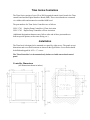
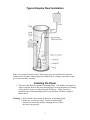
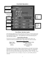
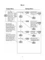
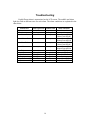
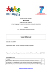
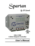
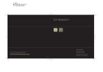
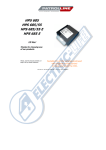
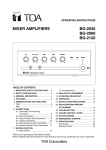
Titan Series
Float Operated
Pump Controllers
By CSI Controls
____________________________________
User’s Manual
1025647 Rev. B
Titan Series Controllers
The Titan Series consists of two cULus 508 Recognized control circuit boards: the Titan
control board and the Digital Interface Board (DIB). These circuit boards are connected
via a ribbon cable and mounted on a molded ABS bezel.
The part numbers for Titan Series Controllers are as follows:
CSLC-1701
CSLC-1702
Simplex Pump Controller w/ Float Activation
Duplex Pump Controller w/Float Activation
(Additional designation characters may follow at the end of these part numbers to
indicate special options, such as time dosing, etc.)
Installation
The Titan bezel is designed to be mounted on a panel by eight screws. The panel cut-out
dimensions and screw hole locations are shown in the figure below. Screw holes should
be drilled and tapped for 6-32 x ½” screws.
The Titan Controller is to be mounted only indoors or inside an enclosed control
panel.
Controller Dimensions
(All Dimensions shown in inches)
2
Typical Simplex Float Installation
Note: Care should be taken to insure that sewage gases are not allowed to enter the
control panel, seal panel with an approved sealing means! (Damage caused by sewage
gas is not covered by warranty).
Installing the Floats
1. There are many different options to mounting floats. The installer can simply tie
wrap or strap the floats to the pump discharge pipe at the appropriate levels using
a heavy duty tie wrap or a clamp designed for that use. Floats can also be
installed using a float mounting bracket w/cord snubbers and float weights as
shown above.
Warning: 1. Do not install a float switch in direct line of incoming liquid.
2. Make sure you leave at least 3.5 inches of tether length
between the actual float and the clamping device to allow
the float to tip properly.
3
Wiring
Terminal Description
CSLC-170X
LA
Alarm Power Input, 120Vac
N
Neutral Input
LC
Control Power Input, 120Vac
AUX, AL
Auxiliary HL alarm dry contact
LT
Alarm Light output, 120Vac
P2
Pump 2 Output, 120Vac
P1
Pump 1 Output, 120Vac
SL
Silence Detection Input
V+
+12Vdc (Unregulated)
Aud
Audible Alarm output (Open Collector Output)
AF
Power to Alarm Float
(100mA fused, Auto
CF
Power to Control Floats
resetting)
N
Neutral for Float Power (jump to incoming neutral)
HL
Return for High Level Float
Lag
Return for Lag Pump Float
LD
Return for Lead Pump Float
Off
Return for Pumps Off Float
RO
1
2
3
N
Return for Redundant Off Float
Pump 1 Overload / Overtemp
Pump 2 Overload / Overtemp
Auxiliary Alarm Input
Neutral
Sample Wiring Diagram
4
Controller Operation
Control Circuit
Power Light
Alarm Circuit
Power Light
Float Status
Lights
Alarm Light
& Test /
Silence
Button
High Level
Light
Lag Pump
On Light
Hand Run
Buttons &
Pump Run
Lights
Lead Pump
On Light
Pumps Off
Light
Float Status Indication Lights
Float indication lights show the status of the floats in the basin. If a float is tipped closed
the corresponding LED will be lit. If the floats tip out of sequence it will cause the float
indication lights to flash an error. These lights help to assist in troubleshooting float
errors and station problems.
Float Failure Routine
The Titan float controllers attempt to detect when a system float has failed. The
controller does this by assuming the floats are hung in the correct order in the basin.
Expected Order of Floats in Basin
Simplex Panel
Duplex (or Time Dose) Panel
High Level Float
High Level Float
On Float
Lag (or Override) Float
Off Float
Lead (or Enable) Float
Off Float
The program looks for a float to change its state from Open to Closed or Closed to Open,
and assumes that a changing state indicates that the float is working. The program then
looks at the state of the other floats to see if they are Open or Closed as expected. If a
float is not in the expected state the program marks that float as failed. The failure for the
float will be cleared if its state ever changes, or if power is cycled and the problem is
corrected.
5
Hand-Off-Auto Operation
The “HAND” button on the Titan controller works similarly to a traditional
H-O-A toggle switch. There are three modes that each pump can be in: Hand, Off,
and Auto. In Off mode, the pump is disabled and will not run. To show that the
pump is disabled and will not run, its respective Pump Run LED will flash. In
Auto mode, the pump(s) will run as described in the sections below. In Hand
mode, the pump will run regardless of the Pump On setpoint or the Time Dosing
timers.
The first time the “HAND” button is pressed, the pump status on the LCD screen
will flash, showing that it is being edited. Pressing “HAND” again will cycle
through the three pump options. When the button has not been pushed for 3
seconds, the pump will be put into the mode that is displayed, and the text will
stop flashing. When the pump is running in Hand, you may bring it out of Hand
by pushing the “HAND” button one time, at which point the pump will return to
its previously set mode. To protect the pump against running dry, the controller
will not latch into Hand mode if the liquid level is below the Off float. To force
the pump to run in Hand mode after this point, you must push and hold the
“HAND” button.
Also, if the pump’s overload/overtemp input opens, the pump will be disabled and
flash the Pump Run LED just as in the Off mode. In this case, the alarm will
sound and the pump status on the display will show “Fail.”
The operation detailed below is considered standard operation. Standard operation
may be modified by some controller settings. See “Menus” section for more details.
Basic Operation, (Standard Simplex Controller)
When the liquid level in the basin rises to the Pump On Float, the pump will turn
on. The pump will stay on until the liquid level is below the Pump Off Float. If
the liquid level gets all the way up to the High Level Float, the high level alarm
will sound the audible and flash the alarm light. To silence the audible, press the
TEST/SILENCE button on the face of the controller, or use an external switch to
connect the SL terminal to ground (see sample wiring diagram).
Basic Operation (Standard Duplex Controller)
When the liquid level in the basin rises to the Lead Pump On Float, the lead pump
will turn on. The pump will stay on until the liquid level is below the Pumps Off
Float. After the pump turns off, the pumps will alternate. (For example, if Pump 1
was the lead pump, after it turns off Pump 2 will be the new lead pump, and Pump
1 will now be the lag pump.) However, a permanent Lead Pump may be assigned
in the Level Control Options Menu. If the liquid level gets all the way up to the
Lag Pump On Float, the lag pump will also turn on. A non-adjustable delay
causes the Lag Pump to wait 10 seconds to turn On after the Lead Pump turns On.
If the liquid level gets all the way up to the High Level Float, the high level alarm
will sound the audible and flash the alarm light. To silence the audible, press the
TEST/SILENCE button on the face of the controller, or use an external switch to
connect the SL terminal to ground (see sample wiring diagrams).
6
Basic Operation (Simplex Time Dosing Controller)
When the liquid level in the basin rises to the Pump On Float, the pump will turn
on. The pump will stay on until the liquid level is below the Pump Off Float, or
until the Pump On timer expires, whichever comes first. The pump will then not
be allowed to run again until the Pump Off timer expires and the liquid level is
above the Pump On Float. If the liquid level gets all the way up to the High Level
Float, the pump will turn on regardless of the state of the Pump Off timer. This is
called a Timer Override. The pump will run for the Override On time, or until the
liquid level is below the Pump Off Float, whichever comes first. After it turns off,
the Override Off timer will begin, and the pump will not be allowed to run again
until it expires, even if the liquid level rises above the High Level Float again.
The high level alarm is also activated by the High Level Float, after the adjustable
High Level Time Delay. This delay allows the Timer Override time to pump the
liquid down below the high level before it alarms. To silence the audible, press
the TEST/SILENCE button on the face of the controller, or use an external switch
to connect the SL terminal to ground (see sample wiring diagrams).
Basic Operation (Duplex Time Dosing Controller)
When the liquid level in the basin rises to the Lead Pump On Float, the lead pump
will turn on. The pump will stay on until the liquid level is below the Pump Off
Float, or until the Pump On timer expires, whichever comes first. The pump will
then not be allowed to run until the Pump Off timer expires. After the pump turns
off, the pumps will alternate. (For example, if Pump 1 was the lead pump, after it
turns off Pump 2 will be the new lead pump, and Pump 1 will now be the lag
pump.) If the controller is in 2-field mode, the new lead pump will be able to run
as soon as the level rises back up to the Lead Pump On Float. In 1-field mode, no
pump can run until the Off timer of both pumps has expired. If the liquid level
rises to the Lag Pump On Float, the pump will turn on regardless of the state of
the Pump Off timer. This is called a Timer Override. In 2-field mode, the lag
pump will also turn on after a 10-second lag delay. The pump(s) will run for the
Override On Time, or until the liquid level is below the Pump Off Float,
whichever comes first. After it turns off, the Override Off timer will begin, and
the pump(s) will not be allowed to run again until it expires, even if the liquid
level rises above the Lag On Float again. If the liquid level rises all the way up to
the High Level Float, the High Level alarm will sound the audible and flash the
alarm light. To silence the audible, press the TEST/SILENCE button on the face
of the controller, or use an external switch to connect the SL terminal to ground
(see sample wiring diagrams).
Redundant Off Float Operation
The default operation of the Redundant Off float is to disable the automatic pump
run operation when the float tips down. If a Redundant Off float is not to be used,
this input should be jumped out to the CF terminal. Special programming of the
Titan controller may alter the operation of this float input.
7
Menus
8
Menu Navigation
To advance to the next menu, press the “Menu/Enter” button. When in the display
menu, to go to the main menu, push and hold “Menu/Enter” until you see the
“Level Cntrl Menu” appear on the LCD screen (about 3 seconds). When in the
Main Menu, to select a submenu, press the “Set/Change” button.
Editing Fields
To edit the setting currently being displayed on the screen, press the “Set/Change”
button. The value that is now being edited will begin to flash. To change this
value, press the “Set/Change” button. To move to the next edit digit, or to finish
editing the setting, press the “Menu/Enter” button.
Display Menu
Press Menu/Enter Button to change between menu fields
Pump Status
Shows pump mode: Hand, Off, Auto, or Fail
(Fail shows during overload or overtemp)
Elapsed Time # - (# is Pump number (1 or 2)):
Reads out the total elapsed run time of the corresponding pump.
(Max Value 999999:59:59)
Time shown is in the format of [Hours:Minutes:Seconds.]
Cycle Count # - (# is Pump number (1 or 2)):
Reads out the number of cycles the corresponding pump has
run. (Max Value: 999999)
Override Count - (Time Dose Controllers only):
Reads out the number of times the panel has gone into override mode.
(Max Value: 999999)
High Level Count Reads out the number of times the liquid level has reached high level.
(Max Value: 999999)
Pump # (1 or 2) Timer - (Time Dose Controllers only):
Reads out the remaining time in the current time cycle. If the pump is
running then it indicates the time remaining until the pump shuts off. If the
pump is off then it indicates time remaining until the pump may run again.
Active Alarm
Reads out what alarm condition the panel is currently experiencing. If
there are no alarms, it will read “None”
9
User Settings Main Menu
Press and hold Menu/Enter Button for 3 seconds while in the Display Menu
to enter into this menu. Press the Menu/Enter Button to change between
menu fields.
Level Cntrl Menu - (Level Control Options Menu):
Press Set/Change button to enter into this sub-menu.
Time Dosing Menu - (Time Dosing Options Menu, Time Dose Controllers only):
Press Set/Change button to enter into this sub-menu.
Telemetry Menu - (Modem option only):
Press Set/Change button to enter into this sub-menu.
Alarm History
Press Set/Change button to enter into this sub-menu.
Level Control Options Menu
Lead Pump Set (Duplex Controllers Only):
Press Set/Change button to change this field.
Possible Settings:
Alternate
= Alternate which pump turns on at the lead setpoint every
time a pump runs
Pump 1 is Lead = Pump #1 always turns on at the lead pump setpoint.
Pump #2 always turns on at the lag pump setpoint.
Pump 2 is Lead = Pump #2 always turns on at the lead pump setpoint.
Pump #1 always turns on at the lag setpoint.
Reset Cyc Cnt # - This is the cycle count that can be viewed in the Display Menu
(Reset Cycle Counter to zero, # is Pump number (1 or 2))
Press Set/Change button to change this field.
Possible Settings:
Do Not Reset = Cycle Counter will not reset
Reset Counter = Cycle Counter will reset to 0
Reset E.T.M. # - This is the Elapsed time that can be viewed in the Display Menu
(Reset Elapsed Time to zero, # is Pump number (1 or 2))
Press Set/Change button to change this field.
Possible Settings:
Do Not Reset = Elapsed Time will not reset
Reset Counter = Elapsed Time will reset to 0
10
Time Dosing Options Menu (Time Dose Controllers Only)
Pump # Time On - (Pump Enable Time Setting, # is Pump number (1 or 2))
This is the amount of time the pump will be enabled to run once the level
reaches the “Pump On” (simplex) or “Lead On” (duplex) Float. Note: If
the level reaches the Pump Off Float before time expires, the pump will
shut off and the Pump Disable time will begin.
Time shown is in [Minutes:Seconds] (Maximum time setting is 99:59)
Press Set/Change button to change this field.
Pump # Time Off - (Pump Disable Time Setting, # is Pump number (1 or 2))
This is the amount of time the pump must wait after it completes a run
cycle before it may run again. Note: If the level reaches the Override Float
(Lag) the pump will begin to run regardless of Pump Disable Time.
Time shown is in [Hours:Minutes] (Maximum time setting is 99:59)
To disable Time Dosing, set this field to 00:00.
Press Set/Change button to change this field.
Pump # Ovrrid On - (Pump Enable Time Setting for Override, # is Pump
number (1 or 2))
This is the amount of time the pump will be enabled to run once the level
reaches the Override Float, at which time the system enters the Override
Time Dosing mode.
Time shown is in [Minutes:Seconds] (Maximum time setting is 99:59)
Press Set/Change button to change this field.
Pump # Ovrrid Off - (Pump Disable Time Setting for Override, # is Pump
number (1 or 2))
This is the amount of time the pump must wait after it completes an
Override run cycle before it may run again. Note: The pump will continue
to cycle in override time dosing mode until the level is below the Override
Float when the Override Pump Disable Time expires.
Time shown is in [Hours:Minutes] (Maximum time setting is 99:59)
Press Set/Change button to change this field.
11
Alarm/Override
This setting controls 3 functions of Time Dosing:
Override: When the basin level reaches the Override float (High Level
setpoint on simplex, Lag setpoint on duplex), the panel will
override the Off Timer, and run the pump(s) using the override On
and Off times.
Override Warning: When an override occurs, the panel will sound an
Override Warning Alarm, to signal that an override event is
occurring.
High Level Alarm: When the basin level reaches the High Level setpoint,
the panel will sound a High Level Alarm, to signal that the liquid
level is much higher than expected.
Override
Warning
Override w/Alarms
ON
ON
Override-No Warn
ON
OFF
Overide-No Alrms
ON
OFF
Alarm-No Overide
OFF
OFF
Press Set/Change button to change this field.
Setting
Override
High Level
Alarm
ON
ON
OFF
ON
High Level Delay - (High Level Time Delay, Simplex Controllers Only):
The High Level Alarm will delay according to the set time. If the fluid
level is above the High Level Float for this length of time without
interruption the alarm will begin to sound. Time shown is in
[Minutes:Seconds] (Maximum time setting is 99:59)
Press Set/Change button to change this field.
Number of Fields – (Duplex Controllers Only)
The Time Dosing operation can be set up for One Field or Two Fields.
When set to “Two Fields” each pump will be able to run as soon as its
corresponding Off Timer is complete. During override the two pumps may
run at the same time.
When set to “One Field” each pump will only be able to run when the Off
Timer for both pumps is complete. The two pumps will never run at the
same time.
12
Telemetry Menu (Modem Option Only)
Call Number
Displays the telephone number the modem will call to report alarms and to
check in monthly. This field may hold from 1 to 11 digits.
Press Set/Change button to change this field. Enter the number 1 digit at a
time. If entering less than 11 digits, enter a blank character to signify when
the telephone number has been entered completely.
Note: This number is set at the factory and will not need to be changed
under normal operation.
I.D. Number
Displays the unique identification number assigned to the control panel.
This field will not normally need to be edited. (May contain the numbers
0-9 and the characters A-F.)
Press Set/Change button to change this field.
Note: This number is set at the factory and will not need to be changed
under normal operation.
Initiate Check-In
Press Set/Change button to force the modem to call in. Emails and text
messages will not be sent for this notification. This menu will also display
the status of the modem connection.
Alarm History Menu
This menu displays the last three alarms that have occurred, beginning with the
most recent alarm. On Titan Controllers equipped with a modem, this menu will
also display the date and time the alarm condition occurred.
Auxiliary Inputs
There are three Auxiliary Inputs (labeled 1, 2, and 3) on the DIB, each with its own
alarm. Each has a 120Vac input, and all three share a common Neutral. The power to
these inputs should come from terminal CF, or a fused 120Vac source; all three inputs
must use the same source.
Inputs 1 & 2 are for normally closed contacts, and are specifically used for pump 1 & 2
heat sensor and/or overload. Input 3 is for normally open contacts, and is a general panel
alarm.
Input Rating: 120 Vac, 10mA each
13
Troubleshooting
Each different alarm is annunciated on the LCD screen. The audible and alarm
light also flash at different rates for each alarm. The alarm conditions are explained in the
chart below:
Alarm/Fault
High Level
Timer Override
Alarm Power Fail
Control Power Fail
Alarm Light Flash Audible Flash
2 per sec.
2 per sec.
1 every 4 sec.
1 every 4 sec.
X
1 every 4 sec.
1 every 4 sec.
1 every 4 sec.
X
1 every 4 sec.
Control Fuse
1 every 4 sec.
1 every 4 sec.
Float Failure
Pump 1 Fault
Pump 2 Fault
Auxiliary Input Alarm
Pump 1 is turned Off
Pump 2 is turned Off
X
1 long, 2 short
1 long, 2 short
1 long, 2 short
X
X
X
1 long, 2 short
1 long, 2 short
1 long, 2 short
X
X
Alarm Fuse Fail
14
Other Indication
Aux. Contact Closed
X
Alarm Power LED Off
Alarm Fuse LED Off
Control Power LED Off
Control Fuse LED Off
Alarm Power LED Off
Alarm Fuse LED On
Control Power LED Off
Control Fuse LED On
Float LED Flash
Pump 1 LED Flash
Pump 2 LED Flash
X
Pump 1 Run LED Flash
Pump 2 Run LED Flash
FCC Information
The Federal Communication Commission (FCC) has established rules, which permits this device to be directly connected to the
telephone network. If this device is malfunctioning, it may also be causing harm to the telephone network; this device should be
disconnected until the source of the problem can be determined and until repair has been made. If this is not done, the telephone
company may temporarily disconnect service. The telephone company may make changes in its technical operations and procedures;
if such changes affect the compatibility or use of this device, the telephone company is required to give adequate notice of the
changes. If the telephone company requests information on what equipment is connected to their lines, inform them of the following:
a) The telephone number the device is connected to.
b) The ringer equivalence number (REN).
c) The device uses an RJ11 type jack.
d) The FCC Registration Number.
The REN (Ringer Equivalence Number) is used to determine the number of devices that may be connected to the telephone line.
Excessive RENs on a telephone line may result in devices not ringing in response to an incoming call. In most, but not all areas, the
sum of the REN should not exceed five (5.0). To be certain of the number of devices that may be connected to a line, as determined by
the total RENs, contact the local telephone company.
15
Specifications
Float Status
LEDs thru bezel
Dimensions
10.72"h X 9.85"w X 0.76"d
Mounting
Panel Mount, w/ eight 6-32 x 1/2" screws
Weight
1.5 pounds
Alarm Power Input
115Vac
Control Power Input
115Vac
P1, P2 Output
115Vac, 100 mA max.
LT Output
115Vac, 100 mA max.
Aud Output
Open Collector Output, 75mA max.
V+ Output
+12Vdc, unregulated
Float Inputs
120Vac, 10 mA max.
Aux Inputs
120Vac, 10 mA max.
Aux Alarm Contact Rating
120Vac, 5A max.
Fuse Rating
5mm x 20mm, 3 Amps max.
Terminal Torque Ratings
7.0 inch-lbs.
Controller Temp Range
-40°F (-40°C) to +185°F (85°C)
Humidity
95% non-condensing
Non-Conductive Injection Molded Bezel
Provides NEMA 1 Rating (when mounted through an enclosure)
Blown Fuse Status Lights
3 Year Limited Warranty
CSI Controls, 220 Ohio Street, Ashland, Ohio 44805
Phone 419-281-5767 · Toll Free 1-800-363-5842 · FAX 419-289-2535
©2011 CSI Controls
www.CSIcontrols.com
[email protected]
16