1
MPG LEVEL 1
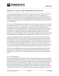
Chapter 11: Serial (not the breakfast kind)
Serial communication seems to be the standard choice of sending data in digital systems these days,
likely because of the relatively small hardware overhead compared to parallel interfaces and the
wickedly fast speeds that are possible despite having only a single data line. You are probably most
familiar with USB and Ethernet – both of these are serial communication protocols. Fire wire and SATA
are other examples. All of these are capable of extremely fast data rates but there is significant
software overhead in implementing them successfully. The protocol complexity of these examples
makes them too complicated for low-level communications needed for basic data transfer within an
embedded system. This is not to say that an embedded system cannot or will not use a fast serial
protocol, but it is typically only done for applications that talk to the outside world like a web server or
USB data connection. On the embedded system itself, the microcontroller and supporting devices
optimize data transfer for power, low latency, low overhead, and hardware simplicity.
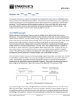
In general, serial protocols have common layers, though each protocol is implemented differently.
These layers correspond to the bottom two layers of the OSI networking model, namely the Physical
layer (PHY) and Data Link layer (MAC). Again, even if your processor does not have the MAC and PHY
built-in, you can often add it externally. The output is single bytes of data. Additional layers to parse
and process the data are added as required, but generally that is where firmware takes over to handle
data in a manner appropriate to a specific system.
This chapter introduces a serial communication protocol that is likely the most commonly used in
embedded systems, RS-232. It is plenty fast enough for onboard communications or debugging services
and almost every microcontroller you can buy will have a hardware peripheral for it. Even if it does not,
then you can always bit-bash a driver to implement it. RS-232 signaling is examined in depth since you
are pretty much guaranteed to come across it as an embedded designer (and you might be lucky enough
to implement it manually). In later chapters we will look at two other very common serial interfaces, the
Serial Peripheral Interface (SPI, pronounced es-pee-eye or spy) and the Inter-Integrated Circuit (I²C,
pronounced eye-squared-see).
11.1 RS-232 Overview
The RS-232 protocol is, or at least was, the defacto standard for serial communication in computer and
embedded systems. Throughout the 1980s and 1990s, pretty much every system that needed to get
data in and out could do so through a serial port and a standard “DB9” connector. Even modems were
built to look like serial ports to a PC. The only real competition for RS-232 was the LPT parallel port, but
the cables were much bulkier and more expensive even though the data throughput was essentially 8
times faster since it was byte-wise rather than bit-wise. Now, of course, those technologies are pretty
much obsolete on mainstream PCs, but embedded designers still make use of them extensively,
notes_mpgl1_chapter11.docx
Release 1.0
Page 1 of 27
MPG LEVEL 1
especially RS-232. A serial connection for debugging or back-up data access is essential in an embedded
system, and there is nothing more simple than RS-232.
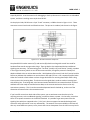
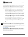
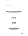
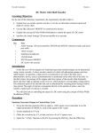
On the physical side, RS-232 uses a 9-pin “D-sub” connector, or DB9 as shown in Figure 11.1.1. These
connectors come in both male and female versions. The pin-out is standard, also shown in the Figure.
Figure 11.1.1: RS-232 connectors and pin out
Complete RS-232 involves transmit (Tx) and receive (Rx) data lines along with several lines used for
hardware flow control amongst other things. These go back to the modem world where additional
signaling was necessary. The terminology uses “Terminal” (usually a PC) and “Device” (usually a modem
in the original context), which are sort of like master and slave, though the protocol is actually full
duplex and both sides can initiate data transfer. With hardware flow control, both the Terminal and the
Device can indicate their readiness to receive data on RTS and CTS lines – this is especially helpful when
either the Terminal or Device does not have a large data buffer for receiving data and/or takes a long
time to process the incoming data. The Device can also signal that it needs to send an incoming byte
with the Ring line. That being said, serial communications with RS-232 can assume that both Terminal
and Device are also ready to send and receive data, so the transmit and receive lines are the only
connections necessary. This is how the course development board is hooked up, so the rest of the
discussion will assume that is the connection used.
If you have full control over both sides of the system, you are welcome to use the other pins for
anything you want, such as additional signaling, connection detect or power. On that note, notice that
there are no power connections in the RS-232 standard. It is possible to get some power from the
signaling lines which are supposed to be +/- 12V, but it does not appear that standard voltage levels
were ever really enforced so it can vary substantially. The amount of current available on the lines will
also vary across different systems, so any circuit that tries to draw power from the 12V lines may load it
notes_mpgl1_chapter11.docx
Release 1.0
Page 2 of 27
MPG LEVEL 1
down too much. If you try to use power from the serial port, you must make sure your embedded
system that is running on 0/5V or 0/3.3V is properly protected from over or under voltage. This also
applies to the signaling lines. There are lots of charge pump / inverter circuits built for RS-232 level
translation just like the MAX3221 on the course development board. Adding this IC to your design is an
example of adding an external PHY to the system.
Typically, devices connect “straight through” so the transmitted data sent on pin 3 is received on pin 3
of the target device. There is an alternate configuration called “null modem” that swaps the transmit
and receive pins. In a way this makes sense because the target device should receive on the receive pin.
This can be a total pain because the cables do not ever seem to be marked to tell you if it is a straightthrough cable or has Tx and Rx swapped. A good quality cable will have “null modem” or “X” (for crossover) or some other indicator to tell you what it is. If it does not, a piece of masking tape works nicely.
To save yourself a lot of time, always label the serial cables you have lying around! However, you still
must know how your system is configured and whether it will be expecting to transmit or receive on pin
2 or pin 3.
11.1.1 Serial Port Configuration
RS-232 is full duplex since there is a dedicated transmit and receive lines, meaning data can be sent and
received simultaneously as long as the peripherals on both ends support that. That being said, most
embedded systems will run in more of a half duplex mode trading messages back and forth in turn.
Prior to communicating, both ends must be configured the same so the message rate and format are
known. Modern RS-232 communication systems offer an “auto bauding” feature that is supposed to
allow the system to determine the clock rate automatically. However, this requires that both systems
know they are trying to auto baud and must send a preliminary data stream of 01010101010101… for a
long enough period that the clock can be determined. It does not always work!
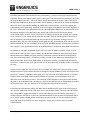
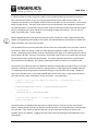
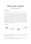
Setting up RS-232 is something that you are probably familiar with even though you might not have
realized it. At some point in your computing experience, you may have configured a dialog box that was
asking for settings like baud rate, flow control, stop bits and data bits (see Figure 11.1.1.1). If you have
ever used a modem or Windows Terminal program, then you have seen this for sure!
Figure 11.1.1.1: Typical RS-232 configuration options
notes_mpgl1_chapter11.docx
Release 1.0
Page 3 of 27
MPG LEVEL 1
A problem with RS-232 can arise because it is asynchronous. It requires a clock signal to generate the
waveform like any other digital system, but the clock signal is not transmitted so each side of the system
has to generate its own clock. The serial clock is usually derived from the system’s main clock source
through some sequence of dividers, prescalers or shift registers. In the case of the course development
board, the clock is generated by dividing the 12MHz main crystal oscillator. As you can imagine, two
independent systems generating “the same” clock are not going to be identical even if their hardware is
the same. Differences in the generated clocks can eventually lead to data errors, so data transfers must
be properly managed. In an ideal world, both sender and receiver have clocks that are exactly
synchronized and do not drift. In such a scenario an endlessly long data stream could be sent without
errors. However, if one clock is slightly faster than the other, then the sampling point of each bit will
drift as more data is sent and eventually fall into the next bit or previous bit resulting in an error.
Computers with GHz core clock speeds can usually generate very good clocks for serial data for even the
fastest standard RS-232 rate of 115kbps. However, some embedded systems will not have a clock that is
fast enough or of the right frequency that can be divided down to support the exact baud rate required.
For example, a low-power embedded system may only have a 32.768kHz crystal for a clock. Since it
takes at least a few instruction cycles to read a bit and deal with a data byte, the system likely cannot
operate faster than 2400bps (this gives just over 13 instruction cycles per bit which should be plenty
even for a bit-bashed receiver). Fortunately, 32768 is a power of two and on most microcontrollers a
power-of-two clock speed can be divided down in hardware to support a standard baud rate with 0%
clock error. To see why that works you will have to look at the processor peripheral, and it is not always
the case.
Another system might have a much faster clock, like 4MHz. This system will have no problem running
enough instruction cycles between data bits to manage the data at 2400bps (or even much higher serial
data rates). However, 4,000,000 is not a power of 2, so it cannot be divided down exactly to provide a
standard serial clock speed. There will be a limitation of how many consecutive bytes can be sent
before the clock drift will be too much. This limitation can be mitigated, or the system clock could be
adjusted to, say 4.192MHz which is divisible by a power of two and thus can be divided down to produce
an exact baud rate. Even then, differences in the system will likely result in some drift.
If the above two systems were talking, the 4MHz system would actually have a harder time staying in
sync than the 32kHz system since it has some error in the generated baud. There are cases where the
first transmitted bit triggers the receiver’s clock and all subsequent bits of however many bytes are
clocked relative to the first bit. In this case, clock drift between the two systems will eventually lead to
errors. Most systems, though, would resynchronize at every start bit, so you can actually have some
pretty high clock errors (or drift over time, temperate, voltage, etc.) and still have very reliable
communication.
notes_mpgl1_chapter11.docx
Release 1.0
Page 4 of 27
MPG LEVEL 1
11.1.2 Signaling
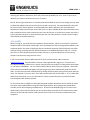
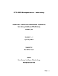
Once communication parameters are set, data is transferred one bit at a time until a byte has been sent
(assuming 8 data bits). The stop and start bits add an additional 2 bits of overhead, so each byte costs
10 bits to send – so RS-232 is only 80% efficient at a maximum. The data lines are in a logic high state
when no traffic is present. A start bit is always a high-to-low transition and the line remains low for the
duration of the bit. The receiver looks for this falling edge of the start bit to know when a frame is
starting. As soon as the start bit is detected, timing starts that controls when each bit is sampled to
determine its value. The receiver uses its baud clock to sample the input data bits and the stop bit.
Data can be MSB or LSB first – there does not tend to be any standard about that, so just ensure that
both systems are the same. If the stop bit is not logic high when it is sampled, then a “framing” error
has occurred (the error would be reported as a flag in one of the serial port registers). There is nothing
physically different between a start bit, a stop bit and a data bit. The start and stop bit are the only two
bits in the frame that have a known (or at least expected) state. The start bit of the next frame can
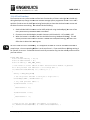
occur immediately after the stop bit of the previous frame. Figure 11.1.2.1 shows an ideal case where
MSB happens to be sent first.
Figure 11.1.2.1: A serial frame with one start bit, one stop bit, no parity and 8 data bits
The bit period is “T” and the frequency of the signal (the baud rate) is 1/T. In most cases of hardware
serial ports, a single bit sample is taken at the half-way point of each byte based purely on timing as
calculated from the start bit falling edge. A more robust system might take 3 or more samples per bit
and then decide on the bit state based on majority rules. Extra sampling is another way to improve data
integrity, though it still does not guarantee perfection.
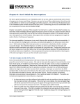
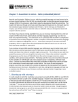
Figure 11.1.2.2 shows an example of the data sampling that would occur if the receiver’s clock is slightly
too fast (or the transmitter’s clock is slightly too slow). The first 4 samples correctly see the start bit and
the first 3 data bits, but the fifth sample ends up sampling the same data bit. From this point on, the
remaining bits are off by one position and the stop bit sample is actually testing the LSB. If the LSB
happens to be 1 (50-50 chance!), then as far as the UART is concerned, the frame is complete and the
notes_mpgl1_chapter11.docx
Release 1.0
Page 5 of 27
MPG LEVEL 1
data byte is valid. Unless the last 5 bits of this byte were 1’s, the received byte will be incorrect but the
system would not have identified the error.
Figure 11.1.2.2: Sampling errors when the receiver clock is too fast
Problems can also occur if there is too much resistance, capacitance, inductance or noise on the
transmission line that causes the signal to distort (see Figure 11.1.2.3). The longer the serial cable
connecting the device, the more capacitance, inductance and resistance is present. If there is noise
source present, then the signal could be further distorted and ones could start looking like zeros or viceversa. Transmit speed will also cause distortion due to parasitic capacitance and inductance in the data
path and further increase the chance of errors when clocks are not synchronized exactly. If you are
having communications problems, sometimes slowing down the baud rate will make the problems go
away. If so, then you have a great hint to prompt yourself to verify the signals.
Figure 11.1.2.3: Poor transmit line (capacitive / resistive)
notes_mpgl1_chapter11.docx
Release 1.0
Page 6 of 27
MPG LEVEL 1
A really nice bonus about bit-bashing a communication protocol is that you can toggle an IO line every
time you sample and see exactly where your sample is reading the incoming data. Just be careful that
the extra instruction cycles to toggle the IO do not disrupt your timing.
Given everything that might happen in a system, it is the designer’s job to create the hardware as best
as possible (limit line lengths, shield wires, etc.) and then implement some sort of scheme to ensure an
acceptable level of data integrity. Like practically every other problem and solution set in engineering,
there are tradeoffs in the choices made. There is a balance between data throughput, probability of
error and error checking, and the right balance will depend on the system requirements. If you need
bullet-proof communications, you may add complex error checking, error correction, data
acknowledgements, checksums, redundancy, etc. All of which will cost you in data overhead and
firmware size and complexity. Making the right decision can be very tricky, but the best you can do is
evaluate your requirements thoroughly.
11.1.3 Bit Errors
The most standard RS-232 communication settings do not include any error checking. A parity bit can
be added to help detect errors (the parity bit is usually the binary sum or XOR of all the data bits). The
problem with a parity bit is that it can only detect an odd-number of errors since an even number of
errors will always cancel each other out. The parity bit itself could be wrong as well. It also adds an
additional bit of overhead, dropping your efficiency down to 70%.
A slightly better approach is to add a checksum byte and perhaps some known signaling bytes within the
data stream. In other words, software managed error control. This also increases the complexity and
overhead in the system. If you are willing to “risk” sending a complete message with a single checksum,
then size overhead is minimized unless of course the checksum is determined to be wrong. Then you
have a lot of overhead as the receiver must somehow inform the transmitter of the problem and the
entire message must be sent again.
A happy medium is to define a message protocol that uses some known pre-amble, a strict message
structure, and some error checking such as a checksum after a complete message. If a message is
typically 10-20 bytes or more, then a few bytes of overhead are reasonable. If the data is non-critical
such as debug messages in text where errors would be obvious (like a missing character), or where
system integrity is known to be quite reliable and an error now and then does not matter, it may be fine
to simply spit out data as fast as possible and not care about errors.
For example, the ANT protocol always sends a known signaling character as the first byte in its message,
and sends a checksum in the last byte that is an XOR of the signaling byte and all the data bytes. This
provides reasonably strong error checking functionality for the system, though it is not completely fail
safe. With more overhead, you can create very solid error detection or even error correction but that is
fairly rare in applications that are generally trading non-critical data. No matter what method of error
notes_mpgl1_chapter11.docx
Release 1.0
Page 7 of 27
MPG LEVEL 1
checking you decide to implement, there will still be some probability for error, and it is up to you to
decide if your system can tolerate any error if it occurs.
Overall, RS-232 is great because it is so widely used and available on any PC (even though you may need
a USB-RS-232 adapter now that most PCs do not include a serial port). The major downfall is the need
for precise clocks, and the problem is compounded when devices operate in the real world where
temperature, battery life and other factors will come in to play. Reliable RS-232 communications pretty
well necessitates that a crystal oscillator be your main clock source, or at least your system must have a
way to calibrate itself prior to communications (but that, too, likely involves a crystal or external signal
of predictable and stable frequency).
11.1.4 ASCII
Before moving on, you need to be up to speed on ASCII characters. ASCII is an acronym for “American
Standard Code for Information Interchange” and is probably one of the most engrained standards in the
computing world. Discussion of ASCII goes hand-in-hand with discussion of RS-232 because very often
character strings are being sent back and forth between an embedded application and a PC. A major
part of this is converting binary data to printable characters, so you will spend lots of time turning
numbers into character strings and vice-versa.
If you are not familiar with the ASCII code set for the first 256 character codes, check out
www.asciitable.com. Common tables are shown a few pages ahead in Figure 11.1.4.1 and 11.1.4.2.
They define the binary number that is sent for each character and symbol, for example the capital letter
‘A’ is 65 (0x41, b’01000001’). You can send any ASCII code you want from your keyboard – almost half
of them from the standard code page just by pressing any key which automatically sends the correct
code. You can also enter ASCII codes directly by holding the Alt key while typing the character code you
want. For example, if you press ALT-6-5 you will send the ASCII code for the letter A. Try it! Codes 248
and 253 are useful often, too, as are the codes for French accented characters if you do not have a
French keyboard but need the symbols.
For the record, there are different code pages and good old 8-bit ASCII where the last half of the codes
was never really standardized has long-since been superseded by 16-bit (and greater) standardized
Unicode, but we will avoid going into detail there. Check out the Wikipedia page on it to learn more…
We will make a fairly safe assumption that we can work safely work with the first 128 character codes
and most of the next 128 character codes and not come across a lot of variance on North American
computers.
notes_mpgl1_chapter11.docx
Release 1.0
Page 8 of 27
MPG LEVEL 1
Figure 11.1.4.1: ASCII characters 0 thru 127
Figure 11.1.4.2: ASCII characters 129 thru 255
notes_mpgl1_chapter11.docx
Release 1.0
Page 9 of 27
MPG LEVEL 1
In programming, you specify an ASCII character value by using single quotes. The computer does not
care how you represent the number, it always stores the binary value, anyway – it is just a matter of
convenience to use a character explicitly. All three of the following are equivalent:
u8 u8Char1 = ‘A’;
u8 u8Char2 = 65;
u8 u8Char3 = 0x41;
Note, however, that the following are NOT equivalent:
u8 u8Char1 = ‘8’;
u8 u8Char2 = 8;
u8 u8Char3 = “8”; /* Error! */
The ASCII character code for the number 8 happens to be 56 (0x38), so the actual value of u8Char1
above is 56. If you check the ASCII table, the decimal value 8 is the backspace character. Also note that
“8” is completely different than ‘8’ in C. “8” is a null-terminated character array, so it would be illegal to
try and make the assignment as shown.
This extends to the problem of sending numbers to character displays like a computer RS-232 terminal
program or an LCD screen. If you have some random number:
u32 u32Number = 1531243414;
How do you print that to an ASCII-based display terminal? The variable u32Number is a binary number
stored in 4 bytes on your embedded system. In hex, the value is 0x5B44EB96. If your first thought is to
just send the bytes, you would break it up byte-wise and send 0x96, 0xEB, 0x44 and 0x5B. Using the
ASCII table, you just sent û, δ, D, and [ - not exactly what you intended, no doubt. When an embedded
system is attached to a terminal program for debugging, the default user interface is usually ASCII. That
means that whatever byte comes through the serial port, that 8-bit binary value is converted to a single
character based on the table. So, if you really want 1531243414 to appear on the screen, you must
parse out the number and send 10 bytes in total for the ASCII characters ‘1’, ‘5’, ‘3’, ‘1’, ‘2’, ‘4’, ‘3’, 4’, ‘1’,
and ‘4’. Likewise, if you were typing that same number in a terminal program and wanted the binary
number to be stored in your embedded system, the 10 ASCII characters would be received and then
built up into the binary.
Because of all this, working with ASCII can be a bit of a pain. Fortunately, there are some standard
library C functions that can take care of translating ASCII to integers and integers to ASCII. The functions
are “atoi()” and “itoa()”. The first of the two, atoi(), is part of the standard C library so including stdlib.h
should make it available. It takes a pointer to a string and returns an int. There is also an atol() function
so you can work with 32-bit values. The second function, itoa(), is not part of the standard C library
though it might be present in your favorite compiler’s library. It is not standard to C because there is a
bit of a problem that should be fairly obvious to you. Think about how you would implement itoa() and
what is the issue that results?
notes_mpgl1_chapter11.docx
Release 1.0
Page 10 of 27
MPG LEVEL 1
The issue is strings in C, namely the fact that there is no string type in C. A function like itoa() will result
in a character array anywhere from 1 digit to (assuming 16-bit integers for now) 5 digits since 65535 is
the maximum 16-bit integer. Variable string lengths have dynamic memory allocation written all over
them, but no one really likes dynamic memory and having a standard C function that uses it is a disaster
waiting to happen. The alternative could be always to return a 5-digit character array, but that is not a
valid return type of a function. You cannot create the array as a variable in the function because the
memory on the stack in the activation record of that function goes away when the function returns. So
then you are stuck with creating an array prior to calling the function and passing a pointer to that array.
That would work, but you still have to manage the varying lengths of the numbers. You would need
leading zeros for numbers with less than 5 digits and then you would need to manage those leading
zeros in your user interface since most of the time people do not like to see them.
There seems to be a lot of trouble surrounding ASCII, strings, numbers and user interfaces, but
unfortunately there are no easy solutions. Things are slightly better in C++ since there is a string type
and itoa() is part of stdlib, but rest assured there is a ton of code behind that, which can eat up precious
space on your embedded system. So you make do with what you need. There are plenty of examples of
ASCII handling in this chapter, so by the time you are finished you should have a pretty good handle on it
all.
11.2 Sending and Receiving Data with Serial Protocols
Most microcontrollers will have several communications peripherals so implementing a protocol is fairly
straight forward with no bit-bashing required. Even if your processor does not have a built-in protocol,
once you bit-bash the basic driver functions you will still reach a point where you have to start using
them to send and receive data using a messaging system that is going to work. There is not really any
point in trying to bit-bash a serial protocol as part of this chapter, so we will focus on the LPC214x
peripheral and look at all that is involved in setting up a decently efficient system for data transfer using
a serial protocol.
Generally speaking, you are probably going to be sending and receiving multiple bytes. Memory for
these byte streams should be set up in unique transmit and receive buffers of contiguous RAM that are
large enough to handle enough bytes, where “enough” is highly system-dependent. Circular buffers are
typically used so several messages can be stacked up and you do not have to worry about overwriting
data that has not yet been sent or examined after being received. A pointer is used to move through
the buffers and transmit or receive each byte in turn (thus the requirement for being a continuous block
in RAM). The easiest way to code a buffer and ensure continuous memory is with an array.
Regardless of the serial protocol used, the MCU peripheral will be able to tell you when a new byte has
arrived in the receive case, and when a byte has finished sending in the transmit case so you can send
another one. Most of the time this will be a flag bit that can also trigger an interrupt if you choose that
approach. To respond to the receive or transmit signals, you have three main options:
notes_mpgl1_chapter11.docx
Release 1.0
Page 11 of 27
MPG LEVEL 1
1. Poll transmit and receive data flags.
2. Use interrupts to grab bytes as they come in or trigger sending the next byte.
3. DMA access to handle all data transfer in the background directly to RAM.
Polling flags is easy but consumes a lot of processor time. If you sit in a dedicated loop waiting for a flag
to be set from the communications peripheral, then the microcontroller can do nothing else. If you
allow the micro to do other things while you are waiting and periodically poll the flag, then your timing
will not be perfect and could cause you to miss bytes in the receive case. Polling is generally not ideal
for busy systems or systems with multiple applications that need processor resources to run. Even in
the simple course firmware system, polling would be unreliable as soon as serial data rates were faster
than the 1ms system period.
The other extreme is to set up direct memory access (DMA) to the serial peripherals. This is slightly
more complicated with a little extra overhead, but works very well especially for transmitting large data
sequences. It can work well for receiving large chunks of data, too, as long as you do not need to be
looking at the data bytes coming in to manage a protocol. Using the ANT protocol as an example again,
it includes a length byte in the message that indicates how many bytes it will send. You cannot start a
DMA transfer until you have this info, and the number of bytes remaining in an ANT message after the
length byte are typically only a few. So in this case, it is probably not worth the trouble.
Taking advantage of interrupts is probably the best way to go at least for receiving data. Though there is
a bit of programming overhead at the beginning to correctly set up the interrupts and write the
interrupt service routines, the actual code that has to run to enable the data transactions will be quite
small and enable the microcontroller to run other applications while the peripherals are busy receiving
data. When the peripherals need attention, the interrupt will fire and allow you to feed or digest the
latest byte in the message as soon as possible.
11.3.1 UART Peripheral Introduction: Physical Layer
After all that background, what we really want to study about RS-232 in the embedded world is a simple
transmit and receive system with no flow control managed by the onboard peripheral since this is the
situation you are most likely to encounter in an embedded system. The LPC214x family has several
peripherals able to speak RS-232 and other serial protocols. Since they are multilingual, they are called
“Universal Asynchronous Serial Transfer” peripherals, or UART for short. If they support synchronous
modes of serial transfer as well, then they are USART peripherals (the “S” is for synchronous).
The fundamental difference between a computer speaking RS-232 and communication on a UART is the
signaling voltage levels. An embedded system typically has a low rail of 0V and a high rail anywhere
from 1.8V to 5V. A computer uses +/- 12V for signaling. To get the two to talk without starting any fires
on your embedded processor, a level converter chip is used. From the embedded system to the PC, the
chip uses a charge pump and inverter circuit to generate +/- signals (they usually end up being around
notes_mpgl1_chapter11.docx
Release 1.0
Page 12 of 27
MPG LEVEL 1
+/-8V
8V which is close enough. From the PC to the embedded system, the chip has buffers that
regenerate the signals at 0 and Vcc voltages. The part doing this on the course development board is
MAX3221 (U5) – the schematic is shown in Figure 11.3.1.1.
Figure 11.3.1.1: RS
RS-232 level converter
The other difference is that UART communications usually only use transmit and receive lines, even
though RS-232
232 devices have CTS, RTS, DCD, DSR, DTR and RING lines. Sometimes CTS and RTS are
supported in hardware, and there a few microcontrollers that su
support
pport all the lines. But generally, it is
transmit (Tx) and receive (Rx). If only Tx and Rx lines are available, the options that can be set are only
those that manage message characteristics including baud rate, stop bits, data bits and parity. The
actual signaling is the same. Baud rate aside, standard configuration for a serial port is typically 8 data
bits, 1 stop bit and no parity and is often simply denoted as “8
“8-n-1” or “8N1”. This configuration
provides close to the maximum data throughput.
11.3.2
.2 UART Peripheral Introduction: Logical Layer
If you have not done so already, open the LPC214x User Manual and read the section on UART0. Even if
you have used a number of UART peripherals on other micros, and even if you have used the LPC214x
peripheral before, it is a good idea to read through the datasheet to ensure you know everything about
the peripheral. A quick scan of the documentation will show you what you already know, tell you what
you need to look at more closely, and hopefully flu
flush
sh out any surprises before you have made critical
decisions in the implementation of the UART.
11.3.2.1 FIFOs
One of the first things that you read in the data sheet on the UART is that there are 16
16--byte buffers for
both transmit and receive built-in
in to tthe
he UART peripheral. The documentation does not use the word
notes_mpgl1_chapter11.docx
Release 1.0
Page 13 of 27
MPG LEVEL 1
“buffer” but rather “FIFO” for First-In-First-Out. When microcontroller datasheets say FIFO, they are
simultaneously telling you that there is a buffer and what the buffer’s behavior is. It might be a bit
clearer to say “FIFO buffer” but in a way it is redundant, too.
Regardless of the terminology, having dedicated buffers in the peripheral is a great feature to have. The
main processor can spend less time worrying about data being sent and received by the UART since it
only needs to ensure that the buffers do not overflow or sit empty when there is data to send. In
essence, having a hardware buffer decreases the minimum required servicing interval of the data by a
factor equal to the length of the buffer. For example, if you were receiving 1600 bytes per second
without a buffer, the main processor would have to read the received character every 1/1600 = 62us to
ensure bytes were not lost. With a 16 byte buffer, the processor could wait until the buffer was full
before getting around to grabbing the data. In this case, it could do so just every 10ms (reading all of
the data out would take only a few microseconds with a 12MHz clock).
11.3.2.2 UART Peripheral Registers
The data sheet quickly gets in to discussing the relevant registers for the UART peripheral. There are a
total of 14 memory locations devoted to data, configuration, or status (the FIFOs are not directly
addressable so they do not appear in the register description). The LPC214x family has two identical
UART peripherals U0 and U1, and each has the same set of registers. If a register is named “FOO”, then
the U0 version of that register will be called U0FOO while the U1 version is U1FOO. If you are talking
about the FOO register in general, you would refer to it as simply FOO or UxFOO.
UxRBR: Receiver Buffer Register is the oldest unread byte that has arrived at the peripheral. In other
words, this is the register you want to read to get the next sequential data. If you are using the receive
FIFO, then this byte is at the top of the buffer (the oldest byte, and still the byte you want to read next).
There is no way to read bytes in the FIFO out of order. Note two very important statements in the data
sheet:
1. The Divisor Latch Access Bit (DLAB) in UxLCR must be 0 in order to access UxRBR. This will be
configured during the setup that we do, but make sure you manage it correctly if you write your
own code.
2. The current PE, FE and BI bits (in the UxLSR status register) correspond to the byte sitting in
UxRBR. These bits flag errors that might have been detected as the byte arrived. Therefore, the
right approach for reading the status bits and data byte is to first read UxLSR and then read
U0RBR. As soon as the current byte in RBR is read, the status bits will change for the next byte
in the FIFO so if you have not read the status bits, the error information will be lost.
So grabbing a byte from the UART peripheral is into a variable is as easy as:
u8 u8ReadByte, u8CurrentStatus;
u8CurrentStatus = U0LSR;
u8ReadByte = U0RBR;
notes_mpgl1_chapter11.docx
Release 1.0
Page 14 of 27
MPG LEVEL 1
Your application should verify the status bits to ensure the byte is clean!
UxTHR: Transmit Holding Register is where the byte you want to send is written. The “DLAB” bit in
UxLCR must be clear to enable access to this register. When the transmit FIFO is enabled, this will be
newest byte in the buffer and thus the last byte that gets sent.
Writing a byte (say 0xAA) to the UART peripheral is as easy as:
U0THR = 0xAA;
As soon as the byte is written, the peripheral will start clocking out the data on the Tx line. That of
course assumes that the UART peripheral is properly set up. Only low level drivers should access
peripheral registers directly. The source code for this chapter shows functions written to provide the
read and write capabilities of the system.
UxDLL, UxDLM and UxFDR: Divisor Latch (LSB and MSB) and Fractional Divider registers. Setting up the
baud rate in a UART is probably the most irritating part of working with the peripheral. Every
microcontroller seems to have its own approach to generating the correct baud rate based on the
system clock frequency in use. Careful reading is required to determine exactly what values are needed
to make the peripheral communicate at the desired baud rate. The LPC214x uses three register in total,
where UxDLL and UxDLM form a 16-bit divider register and UxFDR is a “fractional” divider register
consisting of two values. Together, they reduce the main system clock down to enable generation of the
desired baud rate. For this course, communication is selected at 9600 baud, so let us look at how the
UART needs to be configured to achieve that.
The course development board uses a 12MHz crystal. This crystal source clocks the core but also clocks
all of the peripherals via a derived clock, PCLK. PCLK is the main clock divided down by a certain value
since the peripherals cannot run as fast as the core in some cases. Way back in Chapter 8, configuration
of PCLK was performed and this code is still present in cstartup.s. Since the development board crystal
is less than 20MHz, PCLK does not require scaling and is thus set to also run at 12MHz.
The UART peripheral documentation states that the UART clock must be 16x the desired baud rate:
16 x 9600 = 153600 Hz.
Therefore, PCLK needs to be divided by a factor of 78.125 to get the correct baud rate clock:
12MHz / 153.6kHz = 78.125
If the factor is a whole number, then the 16-bit clock division registers will be able to provide the exact
value for the UART clock and there should not be any error to worry about. However, that is often not
the case, and the microcontroller attempts to provide ways to fractionally divide the main clock since
whole integers cannot be used for scaling. The fractional components (DivAddVal and Mulval) in UxFDR
notes_mpgl1_chapter11.docx
Release 1.0
Page 15 of 27
MPG LEVEL 1
can be used to get the clock closer to the exact value by essentially multiplying the 16-bit divisor by a
factor. Note that to access these registers, the UART peripheral needs to be in configuration mode by
setting the DLAB bit in UxLCR.
Of all the microcontrollers that the author has worked with, the LPC214x UART clock dividers are by far
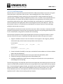
the worst. The full formula from the data sheet to calculate the baud rate is:
That might not seem too bad especially since the (256 x U0DLM + U0DLL) term is really just a single
value, DL. However, solving one equation with three unknowns is still rather difficult. The approach
ends up being iterative with some guess and testing involved to achieve the best value. A spreadsheet is
very helpful, and one has been designed for the course to help in choosing baud rates (see the Excel
spreadsheet LPC214xBaudRateWorksheet.xlsx on the firmware webpage). The spreadsheet works by
making calculations based on the values of the system clock and desired baud rate on the first tab. The
instructions are written inside the spreadsheet. There is a range of about 40 DL values where the
resulting baud rate is reasonable, so each one must be entered to see what the “Best Value” will be until
the absolute best is found. Values for the baud rates in the system are shown from quickly running
through a bunch of iterations of the “DL” value.
Baud Rate
1200
2400
4800
9600
14400
19200
38400
57600
115200
DL
250
125
75
37
25
23
11
1
1
DIVADDVAL
12
12
13
10
13
7
7
12
11
MULVAL
8
8
12
9
12
10
9
1
2
Actual Baud
1200
2400
4800
9602
14400
19182
38352
57692
115385
Error
0.0000%
0.0000%
0.0000%
-0.0178%
0.0000%
-0.0938%
-0.1250%
0.1597%
0.1606%
From this table we can configure the UART peripheral registers to achieve a baud rate very close to
9600. For the fractional divide register U0FDR, bits 3:0 are DIVADDVAL (10 = 0x0A) and bits 7:4 are
MULVAL (9 = 0x09). The code would be written as follows:
U0DLM = 0;
U0DLL = 37;
U0FDR = 0x0A09;
notes_mpgl1_chapter11.docx
Release 1.0
Page 16 of 27
MPG LEVEL 1
UxIER: Interrupt Enable Registers are available to flag various UART interrupts based on events
happening with the peripheral. There are a few different UART interrupts that we will use later on, with
the two most important being an interrupt that indicates new data has been received and another that
indicates that all bytes in the transmit FIFIO have been sent. The datasheet fails to mention the use of
bit 3 in this register, so we assume that it is part of the reserved bits.
UxIIR: Interrupt Identification Register flags when an interrupt has occurred. Strangely enough, the
interrupt sources are coded in three bits, rather than simply using one bit per interrupt source. Since
there are only four interrupt sources, only one additional bit would have been needed to devote a bit
each, yet instead the register has two unused bits and another two redundant bits for FIFO enable.
There is probably some explanation for why NXP designed the peripheral this way, but no such detail is
offered. Note the very important statement below the register’s bit descriptions: “The UxIIR must be
read in order to clear the interrupt prior to exiting the Interrupt Service Routine.”
The descriptions of the interrupt behavior are very important and in reading the information there are
several key pieces of information that will be needed to properly code the UART interrupt handler. The
CTI interrupt is particularly important when using the receive FIFO for incoming messages. Table 105
seems to repeat the same information for the UxIIR bits in Table 104, though provides a bit more detail.
The name of the interrupt bits in Table 104 is listed as “U0IER[3:1]” which appears to be incorrect and
should be “U0IIR[3:1]” (Rev. 3 – 4 October 2010).
UxFCR : FIFO control register configures the behavior of the transmit and receive buffers. This register
allows the buffers to be reset, enabled and configured. For now the FIFOs will be used like single-byte
registers as that is the easiest way to use the UART peripheral when first learning about it.
UxLCR : Line Control Register sets up the data format. This is where the number of data bits, stop bits
and parity bits are selected for the peripheral. This register also contains the DLAB bit which allows
access to the divisor configuration registers when it is set. Microcontrollers often use locking bits or
even passwords to protect access to critical configuration registers. If code ever got out of control and
overwrote random memory values, you would not want your system to stop communicating!
UxLSR: Line Status Register provides feedback on how the peripheral is running or if errors have
occurred that can be detected by the peripheral logic. UxLSR is filled with different status bits that can
be checked by the application to ensure the peripheral is running correctly. For a production-grade
system, all of the status flags should be managed and reacted to so that no operation or error flag is left
untended. For this course, only flags that are of immediate concern will be used.
The remaining registers are for auto-bauding and software flow control of the transmit register. These
are advanced features that we will not worry about for the course. Feel free to explore them on your
own.
notes_mpgl1_chapter11.docx
Release 1.0
Page 17 of 27
MPG LEVEL 1
11.3.2.3 UART Interrupts
Receiver data on an asynchronous protocol like RS-232 is mildly tricky because it can arrive at any given
time unless there is some flow control in place. Data messaging like this is often referred to as
“unsolicited messaging” because nothing our own microcontroller is doing initiated data from the
external system. A perfect example is keyboard input from a user. Humans are very unpredictable and
not very periodic, so a system must be ready to respond to incoming data but still minimize power
consumption and processor cycles. While you could poll the incoming data line, you would have to
ensure you polled at least slightly faster than the incoming data rate to prevent data loss. Given the
bursty nature of data, it is very likely that you would waste an immense amount of time and energy
polling for data that was not present.
The (hopefully by now) obvious answer comes from interrupts. When a character is received, the UART
peripheral can generate an interrupt that can prompt the processor to very quickly grab the byte, throw
it into a receive buffer, then go back to whatever else it was doing.
Communications peripherals tend to get assigned higher priorities than things like buttons, so that is
what we will do for this system. Remember the things required to add an interrupt to the system:
1. Assign the hardware channel to one of the Vector Control registers. We assign VIC_UART0 to
VICVectCntl0 and push the button interrupts down a level of priority.
In interrupts.h:
#define
VICVectCntl0_INIT
(VIC_UART0
| 0x20)
In interrupts.c:
VICVectCntl0 = VICVectCntl0_INIT;
2. Create the handler (Uart0ISR) in interrupts.c and add the function address to the Vector Address
table inside InterruptSetup().
3. Make sure the FIQ / IRQ priority level is set (see the INIT value VICIntSelect_INIT).
4. Enable the interrupt by adjusting the value of VICIntEnable_INIT.
5. Complete Uart0ISR like any other function, making sure to perform the correct operations to
acknowledge the interrupt flag.
The only thing missing is the peripheral-specific interrupt enables that select which interrupt sources are
active in the UART (all the peripheral interrupt sources get ORed into the single UART0 interrupt request
line). From examining the registers already, you should recall that UART interrupt sources include RBR
(Receive Data Available), THRE (Transmit Holding Register Empty) and several status / error sources.
These individual sources are more application-specific and should not be enabled until the UART
application itself is ready to start accepting interrupt requests.
notes_mpgl1_chapter11.docx
Release 1.0
Page 18 of 27
MPG LEVEL 1
11.4 UART Application
The purpose of the UART driver will be to send and receive characters out the serial port to a PC. Since
the driver has quite a bit to it, we will set up the UART application with its own source files. The
assumption is that a human will be on the other end of the connection and will be looking to either get
status information from the system, or type single-letter commands to which the system will respond.
The features of the drivers are as follows:
1. Received bytes from the PC will come in using interrupts. All data will be moved into a receive
buffer local to the UART driver by the interrupt service routine. The receive buffer is a
maximum of UART_RX_BUFFER_SIZE bytes long and is circular. All characters
ters received
r
are
echoed back to the terminal (configurable as a build option).
2. Transmitted bytes will not be sent via interrupts. Whenever the UART application detects that a
new character is in the transmit buffer, one byte will be sent each iteration o
off the application.
This means that the minimum baud rate should be 9600bps since there are 10 bits required per
byte of data, so each byte requires 1.0417ms to be transmitted. If a slower baud rate is chosen,
then data could be overridden in the transmit FIFO on longer messages since bytes would be
queued too quickly. Any application using the UART must not send more than an average of one
byte per millisecond.
3. Outgoing messages will be posted to a transmit buffer by other applications using the
UartQueueTxString()
eTxString() function. These messages must be null-terminated
terminated strings. A carriage
return and linefeed will automatically be added. Maximum message length is 254 bytes.
4. External applications may use the function UartGetChar() to read the latest char and remove it
from the UART application receive buffer. If no new chars are present, the function will return
NULL.
The driver could be improved in many ways, but this simple starting point is enough to allow us to see
both transmit and receive functionality
ctionality in action. The above constitutes the design portion of the code,
so now all we have to do is write it! Much of the shell has been written for you, though there is plenty
left for you to complete. Download the Chapter 11 start code now and take
e some time to see what you
have to work with. The code you need to add is described in the next few sections. As usual, search for
“$$$$” to find the locations where you need to add code.
11.4.1 UART setup
We have already looked at the UART peripheral registers and now need to set them specifically for this
application. If you look at the uart.h header file, you can see a bunch of definitions for all the RS-232
RS
options. The plan is to allow easy configuration of the peripheral settings even though for now we will
hard-code the setup values during initialization
initialization.
As with every application we have written so far, an initialization function and the main application
function pointer call must be added to main. Uart0Init() takes care of the peripheral register setup and
notes_mpgl1_chapter11.docx
Release 1.0
Page 19 of 27
MPG LEVEL 1
the important application initializations like configuring the receive buffer and its pointers. The receive
buffer will be implemented as a circular buffer, so two pointers are required to use it:
1. GGpu8UartRxBufferNextChar
RxBufferNextChar – a global pointer used by the UART interrupt service routine to
place characters into
to the receive buffer. This pointer should always point to the location in the
buffer where the next character will be added.
2. LGpu8UartRxBufferCurrentChar – a local pointer that the UART application will use for parsing
the buffer. This pointer will always follow GGpu8UartRxBufferNextChar.. The buffer is empty
when LGpu8UartRxBufferCurrentChar = GGpu8UartRxBufferNextChar.
Zeroing the application’s receive buffer is done for you already, but initializing the two pointers is not.
You will also need to turn on the power to the UART peripheral by setting the correct PCONP bit.
Configuration of the peripheral registers is already completed. Look at this
is code and the choices
choice made
for each of the peripheral registers to ensure you understand what is being loaded. Note how the DLAB
bit in U0LCR is managed properly to allow access to certain registers. U0LCR is loaded with the
configuration data and U0FCR
R is initialized to allow receive interrupts as soon as a character is received.
The U0FCR_INIT value also takes care of enabling and zeroing the transmit and receive FIFOs. The
proper baud rate is set by indexing the appropriate values from the set arrays
ys indexed by the baud rate
enum.
The VIC has already been setup with the UART interrupt configuration that the system requires. All that
remains is to select which of the UART interrupts are active – we only want to know when received data
is available. Write the value for U0IER_INIT to make this happen.
Build and run the program and check tthat Uart0Init correctly initializes your receive buffer and its
pointers (add the two pointers to a watch window, followed by the receive buffer
buffer).. You should see
se
something similar to Figure 11.4.1.1 with the important part being that the address held by both the
pointers is equal to the starting address of the receive buffer
buffer.
Figure 11.4.1.1: Initialized receive buffer variables
notes_mpgl1_chapter11.docx
Release 1.0
Page 20 of 27
MPG LEVEL 1
Any code past Uart0Init() that runs is incomplete, so the program might crash or do bizarre things – do
not worry about that yet!
11.4.2 Private and Protected Functions
The only private function in the driver is called UartSendByte() and is responsible for loading a character
into the Transmit Holding Register. When this happens, it queues the UART peripheral to clock out the
data byte (or at least it will add it to the transmit FIFO and it will eventually be clocked out). This
function has an argument that allows it to be used w
with either UART0 or UART1, which is accomplished
by adjusting a pointer to the correct THR register. All that remains for you to do in the function is to
write one line of code that puts u8Data_ into the THR.
Aside from Uart0Init, there are two other protected functions. UartForceSend() is a special function
used to make the UART state machine operate during initialization when the 1ms system loop is not yet
executing. We have seen this in previous chapters so no work is required and it will not be discussed
d
further.
AdvanceUartRxBufferNextCharPointer
AdvanceUartRxBufferNextCharPointer() is a very important function that takes care of managing the
pointer for new received characters. Notice that it has the requirement that it is only called from
Uart0ISR(). It advances the pointer aand checks it for wrap-around
around of the circular buffer. The UART
interrupt handler calls this function every time a character is received. It has to be a protected function
to uart.c because it references LGau8UartBufferRx
LGau8UartBufferRx[] whose scope is not beyond uart.c (according to our
rules!) but the UART handler is in interrupts.c
interrupts.c.
AdvanceUartRxBufferNextCharPointer()
() does is manipulate a variable
The “dangerous” operation that AdvanceUartRxBufferNextCharPointer
that is also used in Uart0Isr(). Since we know only the ISR needs this function, we can write it as-is
as (with
the “Requires” information as a warning). Interrupts are off inside an interrupt service routine, so this
function cannot be interrupted by another UART interrupt that could result in accessing the wrong piece
of memory (including a byte outside of the receive buffer array) if the interrupt happened at just the
wrong time.. If this function was needed elsewhere, then we would have to disable interrupts while the
pointer was being moved and re-enable
enable them after to ensure that our ad
addressing
dressing remained correct.
The second thing this function does is flag that a new character has been received by setting
_UART_NEW_RX_CHAR in LGu32UartFlags
LGu32UartFlags.. Again, this relies specifically on the fact that we know this
function is called only from the UART ISR when a character is received. Adding the flag here allows us to
keep it local to the uart.c source code. This flag is an important part of the driver’s functionality.
11.4.3 API Functions
The public functions that allow other applications to use the UART driver are UartQueueTxString()
UartQueueTxString and
UartGetChar(). There are a few lines of code for you to add in each to complete them.
notes_mpgl1_chapter11.docx
Release 1.0
Page 21 of 27
MPG LEVEL 1
If a function wants to send a string to the UART, it calls UartQueueTxString() and passes a pointer to a
NULL-terminated character array (a C-string) that gets parsed into the UART transmit buffer. The
characters are counted in a local global variable so the total number of unsent characters in the transmit
buffer is always known. The bytes will be sent out one-per-millisecond in the subsequent iterations of
the UART application. Note that the transmit buffer used by this function is NOT the peripheral transmit
FIFO, so no need to worry about overflow if your message is longer than 16 bytes. There is a limit of
UART_TX_BUFFER_SIZE – 2 bytes, though.
Many embedded systems create printf-like functions to direct output to a UART. While this adds some
familiar C-programming functionality to the system, the implementation is more difficult to explain then
doing it manually, hence we choose this way!
The second API function retrieves the latest character from the receive buffer if any character is there to
be retrieved. When a character is read, the UART application updates its buffer so the space can be
reused. UartGetChar() works FIFO just like you would expect, but again, it has nothing to do with the 16
byte peripheral Rx FIFO. If there is no character, the function returns NULL, so any application using this
function would have to handle that appropriately. If a system required that NULL be a valid character,
this would have to be adjusted. This system is expecting only ASCII characters, so it should be safe.
The portion of the code that checks for additional characters must disable interrupts to do so, since new
characters could come in while this function is being executed. If that happened immediately after the
“if” statement, then the flag would be cleared even though a new character had arrived. Though the
next time a character came in this problem would likely correct itself, there is a high chance that every
now and then the system would appear to lose a character – not a good idea!
/* Check to see if there are additional characters - interrupts must be off! */
__disable_interrupt();
if(LGpu8UartRxBufferCurrentChar == GGpu8UartRxBufferNextChar)
{
/* Clear flag */
LGu32UartFlags &= ~_UART_NEW_RX_CHAR;
}
/* Critical check complete, so re-enable interrupts */
__enable_interrupt();
The two functions to disable/enable interrupts are called “intrinsic” functions as they are processorspecific. IAR has special provisions for functions like this as there is no C-equivalent that could complete
the same task. If you search through the IAR code, you will eventually find that the functions are
probably written in assembler. Toggling interrupt states is done by flipping the FIQ and IRQ bits in the
CPSR register.
notes_mpgl1_chapter11.docx
Release 1.0
Page 22 of 27
MPG LEVEL 1
11.4.4 Test Function
Test functions are very often used to confirm basic functionality of drivers and might be included only
during development,, though are often left available through special programmer access.
access Let us add a
quick bit of code to test the UART transmitting functionality to show that the baud rate is correct and
the driver functions are working.. The code will do the following:
1. Send individual ASCII characters to the UART peripheral using UartSendByte() at a rate of one
every 20ms but only when BUTTON0 is held down.
2. Characters sent should only be p
printable characters, ASCII codes 33 – 127 and 160 – 255.
3. When the button is released, a new line should be ssent
ent using UartQueueTxString(). This
T will
actually send two new lines since another is added with UartQueueTxString(), but that is the
effect that is desired so it works great.
All of this code will live in UartSMIdle(). It is wrapped in an #ifdef so it can be included or excluded at
compile time – the corresponding #define is at the top of uart.h. If you would like to challenge writing it
for yourself, do so now. A solution iiss shown here that you need to copy into the code if you do not write
your own version.
#ifdef UART_TEST
static u8 au8LineFeed[] = "\
\n\r";
static u8 u8CurrentChar = '!';
static u8 u8Delay = UART_TEST_DELAY;
/* Test function: send a stream of ASCII characters while BUTTON0 is pressed.
Use a delay between each character to slow things down. */
if( IsButtonPressed(BUTTON0) && (
(--u8Delay == 0) )
{
u8Delay = UART_TEST_DELAY;
/* Use the private function
tion to send just a single char */
UartSendByte(UART0, u8CurrentChar++);
/* Only send printable chars! */
if(u8CurrentChar == 127)
{
u8CurrentChar = 160;
}
if(u8CurrentChar == 255)
{
u8CurrentChar = '!';
}
}
/* Send one new line character once BUTTON0 is released */
if ( WasButtonPressed(BUTTON0) && !IsButtonPressed(BUTTON0) )
{
notes_mpgl1_chapter11.docx
Release 1.0
Page 23 of 27
MPG LEVEL 1
UartQueueTxString(&au8LineFeed[0]);
ButtonAcknowledge(BUTTON0);
}
#endif /* UART_TEST */
That just about completes the UART driver. Build the code and run it. The firmware should run
correctly now and the UART test function should work to output characters when BUTTON0 is held.
held
However, one thing is missing. If you type characters into the terminal window, they probably
pro
do not
appear, yet if you halt your code and look at the UART receive buffer, the characters are indeed present.
Figure 11.4.4.1
1 shows the terminal window and a debug watch window with the receive buffer. The
sentence “Where are my chars?” was type
typed
d and as you can see, the UART peripheral got the letters but
they are not on the Terminal.
Figure 11.4.4.1:
1: Terminal window and debug view of receive buffer.
So where are the characters? The issue is that terminal programs are meant to give you a window into
the system without any bells and whistles. Showing you what you typed is a particular bell (or whistle)
that is probably not desirable for the most part because the window should (technically) show you just
the remote device’s communications. There are two solutions to this problem. The first is to turn on
“local echo” in the terminal window. In Tera Term, this is under Setup > Terminal as shown in Figure
Figu
11.4.4.2. Activating this setting will echo the characters back locally in the terminal window.
notes_mpgl1_chapter11.docx
Release 1.0
Page 24 of 27
MPG LEVEL 1
Figure 11.4.4.2: Tera Term Terminal setup window
Notice the “New-line” options as well. When the “Enter” key is pressed, different systems (Window,
Linux, Mac) might send different characters. Windows typically sends a line feed (‘LF’, ASCII 0x0A) and a
carriage return (‘CR’, ASCII 0x0D). This probably dates way back to typewriters when pressing “return”
caused the carriage to swing back and also added a line. Regardless, be aware that these settings exist.
To make our test system work well, set “Transmit” to CR+LF as shown.
The second option for echoing characters to the terminal window is to have the system echo them back.
This is often the default setting for terminal programs and it makes sense. If the target device echoes
the character, then you know for sure it has received it correctly, processed it in some way, and verified
communication back to the terminal program. The problem is that this functionality has to be
programmed in firmware.
To do this properly, you have to handle cases of special characters, most often “backspace” and the new
lines. A new line is typically used to indicate that the user has provided information and now wants the
system to respond, so those characters are often continually searched for. All the characters found prior
to the line feed become the candidate command. Certain systems may need to handle other special
characters, too. The code can become quite complicated, especially if your receive buffer must also
handle the control characters.
For our UART driver, we will cheat a little and do a very basic echo function and not respond to any
control characters. Generally this will work just fine and the only strange behavior that you will notice is
with backspace. The cursor will move backward in the terminal window, but the character it backspaces
to will not be erased. The backspace ASCII code (0x08) will also just be loaded to the receive buffer
rather than instigating the deletion of the previous character in the buffer as you may expect. This is
purposely left like this to illustrate the point and make you think about it when it comes time to writing
notes_mpgl1_chapter11.docx
Release 1.0
Page 25 of 27
MPG LEVEL 1
a full service driver. MPG Level 2 builds a debug application that fully implements a similar UART driver
but it correctly deletes
tes characters on back
backspace and parses message on new lines.
So, can you figure out where the logical place to echo the character would be? And what function
fu
would you call to make it happen in a single line of code? The suggested spot is flagged in the source
code. It is also wrapped in the #ifdef UART_ECHO so the feature can be easily switched on and off
depending on the target system (who knows, may
maybe
be the terminal program you use always has local
echo on, so you would not want your system echoing characters back). Add the line of code and try it
out. Try out the terminal settings with Local Echo on and off as well.
As you can see, there really is not much tto setting up the UART to be used, but there is a bunch of things
to keep in mind when coding the rest of the driver operation
operation.. Once the configuration is done the
peripheral is essentially ready to go. A few lines of code provide transmit and receive
eceive functionality, and
just like that your processor can communicate to the outside world!
11.5 Chapter Exercise
To test out the UART driver, complete the following four activities all in Chapter11SMIdle()
Chapter11SMIdle in
chapter11.c:
1. Print your name to the UART po
port when BUTTON1 is pressed. Leave the BUTTON0 test code in
place so that functionality wil
will still work.
2. Add a 4-digit
digit counter that increments and prints the count value underneath your name every
time it prints. Make sure it rolls back to 0 after 9999. Print leading zeros. It should look like
this:
notes_mpgl1_chapter11.docx
Release 1.0
Page 26 of 27
MPG LEVEL 1
3. Monitor the receive buffer and look for the characters W,P, B, C, G, Y, O and R. Any time one of
those characters is detected, toggle the corresponding LED. You may not use the private
LedToggle() function in the LED driver, so you will have to keep track of the LED states by adding
flags to LGu32Chapter11Flags. It is suggested to work with just one LED to get it operating
properly, then copy and paste that code to make the remaining 7 LEDs work. Do not do the
backlight LEDs.
4. Update the LED functionality to work with both lower case and uppercase command characters.
notes_mpgl1_chapter11.docx
Release 1.0
Page 27 of 27