1
Series
MES Interface Function Manual
for GT Works3
SAFETY PRECAUTIONS
(Always read these precautions before using this product.)
Before using the product, please read this manual and the relevant manuals introduced in this manual
carefully and pay full attention to safety to handle the product correctly.
The precautions given in this manual are concerned with only this product.
In this manual, the safety precautions are ranked as "WARNING" and "CAUTION".
WARNING
Indicates that incorrect handling may cause hazardous conditions, resulting in
death or severe injury.
CAUTION
CAUTION Indicates that incorrect handling may cause hazardous conditions,
resulting in minor or moderate injury or property damage.
Note that the
CAUTION level may lead to serious consequences according to the circumstances.
Always follow the precautions of both levels as they are important for personal safety.
Please save this manual to make it accessible when required and always forward it to the end user.
[Design precautions]
WARNING
Before performing the test operation, read this manual carefully to understand the operation
procedure.
Incorrect output or malfunctions may cause an accident.
When the security of the GOT and relevant information need to be protected against illegal access
from an external device via the Internet, take measures at the user's discretion.
Failure to do so may cause the configured information to be read out illegally.
A-1
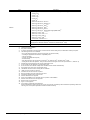
CAUTIONS FOR USE
Cautions on the system configuration
(1) GOTs that support the MES interface function
GT16 and GT15 only support the function.
By installing the option OS into a GOT from GT Designer3, the MES interface function can be used.
For applicable models, refer to the following:
2.2 Connection between GOT and Controllers
(2) Option function board that supports the MES interface function
For the option function board that supports the MES interface function, refer to the following:
2.3 Required Equipment, Software and Option OS
(3) Relational databases that support the MES interface function
For the relational databases that support the MES interface function, refer to the following:
2.4.2 Server computer (SNTP server computer)
(4) Connection type used for the MES interface function
To utilize the MES interface function, the Ethernet connection is used.
Install an Ethernet communication unit, and configure the Ethernet setting in Communication Settings of GT
Designer3.
For applicable Ethernet communication units, refer to the following:
2.3 Required Equipment, Software and Option OS
For the Ethernet connection, refer to the following.
GOT1000 Series Connection Manual (Mitsubishi Products) for GT Works3
A-2
INTRODUCTION
Thank you for purchasing the Mitsubishi Graphic Operation Terminal (GOT).
Before using the GOT, please read this manual carefully to understand the features and performance for
correct handling.
CONTENTS
SAFETY PRECAUTIONS .........................................................................................................................A - 1
CAUTIONS FOR USE ..............................................................................................................................A - 2
INTRODUCTION ......................................................................................................................................A - 3
CONTENTS ..............................................................................................................................................A - 3
MANUALS.................................................................................................................................................A - 7
QUICK REFERENCE ...............................................................................................................................A - 9
ABBREVIATIONS AND GENERIC TERMS ...........................................................................................A - 11
HOW TO READ THIS MANUAL ............................................................................................................. A - 16
DEFINITIONS AND DESCRIPTIONS OF TERMS .................................................................................A - 17
1. OVERVIEW
1.1
Features........................................................................................................................................... 1 - 2
1.2
What is the MES Interface Function? .............................................................................................. 1 - 6
2. SYSTEM CONFIGURATION
2.1
System Configuration ...................................................................................................................... 2 - 1
2.1.1 Overall system configuration ................................................................................................ 2 - 1
2.1.2 System configuration when installing software used for the MES Interface Function .......... 2 - 2
2.2
Connection between GOT and Controllers...................................................................................... 2 - 3
2.2.1 Connection type used for the MES Interface Function ......................................................... 2 - 3
2.2.2 Precautions for inverter or servo amplifier connection ......................................................... 2 - 5
2.3
Required Equipment, Software and Option OS ............................................................................... 2 - 6
2.4
Operating Environment.................................................................................................................... 2 - 7
2.4.1 Configuration computer ........................................................................................................ 2 - 7
2.4.2 Server computer (SNTP server computer) ........................................................................... 2 - 7
2.5
Cautions on System Configuration ................................................................................................ 2 - 10
3. SPECIFICATIONS
3.1
Performance Specifications ............................................................................................................. 3 - 1
3.2
GOT Devices Available for the MES Interface Function.................................................................. 3 - 3
3.3
Function List and Setting Item List................................................................................................... 3 - 4
3.4
GOT Internal Device (GS) ............................................................................................................... 3 - 6
3.4.1 GOT internal device list ........................................................................................................ 3 - 6
3.4.2 MES Interface Function area ................................................................................................ 3 - 6
A-3
4. SETTINGS AND PROCEDURES BEFORE USE OF THE MES INTERFACE
FUNCTION
4.1
Settings and Procedures before Use of the MES Interface Function .............................................. 4 - 1
4.2
Installation and Uninstallation .......................................................................................................... 4 - 3
5. MES INTERFACE FUNCTION
5.1
DB Interface Function ...................................................................................................................... 5 - 1
5.1.1 DB interface function operation ............................................................................................ 5 - 1
5.1.2 Job execution procedure ...................................................................................................... 5 - 2
5.1.3 Tag function .......................................................................................................................... 5 - 3
5.1.4 Trigger monitoring function ................................................................................................... 5 - 4
5.1.5 Trigger buffering function...................................................................................................... 5 - 6
5.1.6 SQL text transmission (Communication action).................................................................... 5 - 9
5.1.7 Arithmetic processing function (Operation action) .............................................................. 5 - 10
5.1.8 Resource data send function (Resource data send action)................................................ 5 - 11
5.1.9 Program execution function ................................................................................................ 5 - 14
5.1.10 DB buffering function .......................................................................................................... 5 - 15
5.2
SNTP Time Synchronization Function ........................................................................................... 5 - 23
5.3
Precautions .................................................................................................................................... 5 - 24
6. MES INTERFACE FUNCTION SETTING
6.1
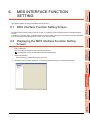
MES Interface Function Setting Screen........................................................................................... 6 - 1
6.2
Displaying the MES Interface Function Setting Screen ................................................................... 6 - 1
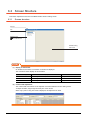
6.3
Screen Structure .............................................................................................................................. 6 - 2
6.3.1 Screen structure ................................................................................................................... 6 - 2
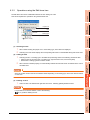
6.3.2 Operations using the Edit items tree..................................................................................... 6 - 3
6.4
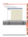
Setting.............................................................................................................................................. 6 - 5
6.5
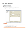
Device Tag Settings......................................................................................................................... 6 - 6
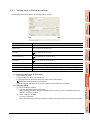
6.5.1 Setting items in Device tag settings...................................................................................... 6 - 7
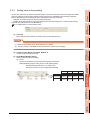
6.5.2 Setting items in Array setting ................................................................................................ 6 - 9
6.5.3 Setting items in Component setting .................................................................................... 6 - 11
6.6
Server Service Settings ................................................................................................................. 6 - 17
6.6.1 Setting items in Server service settings.............................................................................. 6 - 18
6.7
Job Settings ................................................................................................................................... 6 - 21
6.7.1 Setting items in Job settings ............................................................................................... 6 - 22
6.7.2 Setting items in Trigger conditions...................................................................................... 6 - 25
6.7.3 Setting items in Program execution .................................................................................... 6 - 33
6.7.4 Setting items in DB Buffering.............................................................................................. 6 - 36
6.7.5 Notify errors (job cancellation) that occur during job execution .......................................... 6 - 36
6.7.6 One-shot execution............................................................................................................. 6 - 37
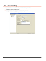
6.8
Job Settings - Actions .................................................................................................................... 6 - 38
6.8.1 Setting items in Communication action............................................................................... 6 - 42
6.8.2 Setting items in Operation action........................................................................................ 6 - 62
6.8.3 Setting items in Transmit resource action........................................................................... 6 - 65
6.9
Option Setting ................................................................................................................................ 6 - 78
6.9.1 Setting items in SNTP time synchronization setting ........................................................... 6 - 79
A-4
6.9.2
Setting items in DB buffering settings................................................................................. 6 - 81
6.10 Diagnosis ....................................................................................................................................... 6 - 85
6.10.1 Checking the MES Interface Function status (Status) ........................................................ 6 - 86
6.10.2 Manipulating the MES Interface Function status (Operation) ............................................. 6 - 87
6.10.3 Changing the job status (Change job status) ..................................................................... 6 - 88
6.10.4 Checking the connection of the previous job execution
(Connection result of previous job execution) .................................................................... 6 - 89
6.10.5 Manipulating DB buffering (DB buffering operation) ........................................................... 6 - 90
6.10.6 Checking the trigger buffering (Trigger buffering status) .................................................... 6 - 91
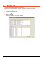
6.11 Working Log................................................................................................................................... 6 - 92
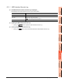
6.11.1 MES Interface Execute Log ................................................................................................ 6 - 93
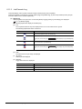
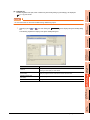
6.11.2 Job Execute Log ................................................................................................................. 6 - 94
6.12 Precautions.................................................................................................................................... 6 - 98
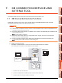
7. DB CONNECTION SERVICE AND SETTING TOOL
7.1
DB Connection Service Functions ................................................................................................... 7 - 1
7.2
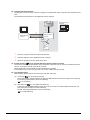
Setting ODBC of Database.............................................................................................................. 7 - 3
7.3
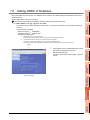
Starting DB Connection Service Setting Tool ................................................................................ 7 - 11
7.4
Screen Structure of DB Connection Service Setting Tool ............................................................. 7 - 12
7.4.1 Screen structure ................................................................................................................. 7 - 12
7.4.2 Menu configuration ............................................................................................................. 7 - 12
7.5
Setting Items of DB Connection Service Setting Tool .................................................................. 7 - 13
7.6
Importing/Exporting Files .............................................................................................................. 7 - 17
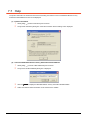
7.7
Help ............................................................................................................................................... 7 - 18
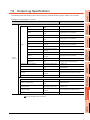
7.8
Output Log Specifications.............................................................................................................. 7 - 19
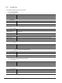
7.8.1 Access log .......................................................................................................................... 7 - 20
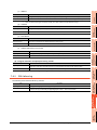
7.8.2 SQL failure log .................................................................................................................. 7 - 21
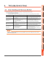
8. TROUBLESHOOTING
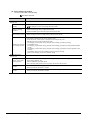
8.1
Error Handling and Recovery Method ............................................................................................. 8 - 1
8.1.1 MES Interface Function setting ............................................................................................ 8 - 3
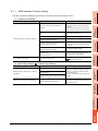
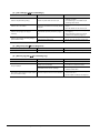
8.1.2 When using DB Connection Service Setting Tool ................................................................ 8 - 5
8.2
Error Code List................................................................................................................................. 8 - 6
8.2.1 Error log in the Working log .................................................................................................. 8 - 6
8.2.2 DB Connection Service ...................................................................................................... 8 - 10
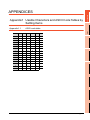
APPENDICES
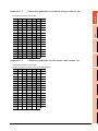
Appendix1 Usable Characters and ASCII Code Tables by Setting Items ............................................. App - 1
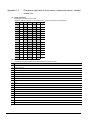
Appendix.1.1 ASCII code table .........................................................................................................App - 1
Appendix.1.2 Characters applicable to item names, component names, variable names, etc. ........App - 2
Appendix.1.3 Characters applicable to character string constants, etc............................................. App - 3
Appendix.1.4 Characters applicable to field names, table names, etc. ............................................. App - 3
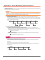
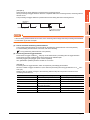
Appendix2 About Monitoring Interval Timeout....................................................................................... App - 4
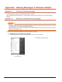
Appendix3 Warning Messages in Windows Vista(R) ............................................................................App - 6
Appendix.3.1 Overview of warning messages ..................................................................................App - 6
Appendix.3.2 Methods for disabling warning messages ................................................................... App - 6
Appendix4 Tables for Used Terms ......................................................................................................App - 12
A-5
Appendix5 Application Example of MES Interface Function................................................................App - 13
INDEX
REVISIONS
A-6
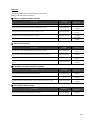
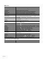
MANUALS
The following table lists the manual relevant to this product.
Refer to each manual for any purpose.
Screen creation software manuals
Manual Name
GT Works3 Version1 Installation Procedure Manual
Packaging
Enclosed in product
GT Designer3 Version1 Screen Design Manual (Fundamentals) 1/2, 2/2
Stored in DVD-ROM
GT Designer3 Version1 Screen Design Manual (Functions) 1/2, 2/2
Stored in DVD-ROM
GT Simulator3 Version1 Operating Manual for GT Works3
Stored in DVD-ROM
GT Converter2 Version3 Operating Manual for GT Works3
Stored in DVD-ROM
Manual Number
(Model code)
SH-080866ENG
(1D7MB9)
SH-080867ENG
(1D7MC1)
SH-080861ENG
(1D7MB1)
SH-080862ENG
(1D7MB2)
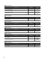
Connection manuals
Manual Name
Packaging
Manual Number
(Model code)
GOT1000 Series Connection Manual (Mitsubishi Products) for GT Works3
Stored in DVD-ROM
SH-080868ENG
(1D7MC2)
GOT1000 Series Connection Manual (Non-Mitsubishi Products 1) for GT Works3
Stored in DVD-ROM
SH-080869ENG
(1D7MC3)
GOT1000 Series Connection Manual (Non-Mitsubishi Products 2) for GT Works3
Stored in DVD-ROM
SH-080870ENG
(1D7MC4)
GOT1000 Series Connection Manual (Microcomputer, MODBUS Products, Peripherals) for GT
Works3
Stored in DVD-ROM
SH-080871ENG
(1D7MC5)
Extended and option function manuals
Manual Name
Packaging
Manual Number
(Model code)
GOT1000 Series Gateway Functions Manual for GT Works3
Stored in DVD-ROM
SH-080858ENG
(1D7MA7)
GOT1000 Series MES Interface Function Manual for GT Works3
Stored in DVD-ROM
SH-080859ENG
(1D7MA8)
GOT1000 Series User's Manual (Extended Functions, Option Functions) for GT Works3
Stored in DVD-ROM
SH-080863ENG
(1D7MB3)
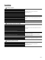
GT SoftGOT1000 manuals
Manual Name
GT SoftGOT1000 Version3 Operating Manual for GT Works3
Packaging
Stored in DVD-ROM
Manual Number
(Model code)
SH-080860ENG
(1D7MA9)
A-7
GT16 manuals
Manual Name
Packaging
Manual Number
(Model code)
GT16 User's Manual (Hardware)
Stored in DVD-ROM
SH-080928ENG
(1D7MD3)
GT16 User's Manual (Basic Utility)
Stored in DVD-ROM
SH-080929ENG
(1D7MD4)
GT16 Handy GOT User's Manual
Stored in DVD-ROM
JY997D41201
JY997D41202
(09R821)
GT15 manuals
Manual Name
GT15 User's Manual
Packaging
Stored in DVD-ROM
Manual Number
(Model code)
SH-080528ENG
(1D7M23)
GT14 manuals
Manual Name
GT14 User's Manual
Packaging
Stored in DVD-ROM
Manual Number
(Model code)
JY997D44801
(09R823)
GT12 manuals
Manual Name
GT12 User's Manual
Packaging
Stored in DVD-ROM
Manual Number
(Model code)
SH-080977ENG
(1D7ME1)
GT11 manuals
Manual Name
Packaging
Manual Number
(Model code)
GT11 User's Manual
Stored in DVD-ROM
JY997D17501
(09R815)
GT11 Handy GOT User's Manual
Stored in DVD-ROM
JY997D20101
JY997D20102
(09R817)
GT10 manuals
Manual Name
GT10 User's Manual
A-8
Packaging
Stored in DVD-ROM
Manual Number
(Model code)
JY997D24701
(09R819)
QUICK REFERENCE
Creating a project
Obtaining the specifications and operation methods of GT Designer3
Setting available functions on GT Designer3
Creating a screen displayed on the GOT
GT Designer3 Version1 Screen Design Manual
(Fundamentals) 1/2, 2/2
Obtaining useful functions to increase efficiency of drawing
Setting details for figures and objects
Setting functions for the data collection or trigger action
GT Designer3 Version1 Screen Design Manual (Functions)
1/2, 2/2
Setting functions to use peripheral devices
Simulating a created project on a personal computer
GT Simulator3 Version1 Operating Manual for GT Works3
Connecting a controller to the GOT
Obtaining information of Mitsubishi products applicable to the GOT
Connecting Mitsubishi products to the GOT
GOT1000 Series Connection Manual (Mitsubishi Products) for
Connecting multiple controllersto one GOT (Multi-channel function)
GT Works3
Establishing communication between a personal computer and a
controller via the GOT (FA transparent function)
Obtaining information of Non-Mitsubishi products applicable to the GOT
• GOT1000 Series Connection Manual (Non-Mitsubishi
Products 1) for GT Works3
Connecting Non-Mitsubishi products to the GOT
Obtaining information of peripheral devices applicable to the GOT
Connecting peripheral devices including a barcode reader to the GOT
• GOT1000 Series Connection Manual (Non-Mitsubishi
Products 2) for GT Works3
GOT1000 Series Connection Manual (Microcomputer,
MODBUS Products, Peripherals) for GT Works3
Transferring data to the GOT
Writing data to the GOT
Reading data from the GOT
GT Designer3 Version1 Screen Design Manual
(Fundamentals) 1/2, 2/2
Verifying a editing project to a GOT project
A-9
Others
Obtaining specifications (including part names, external dimensions, and
• GT16 User's Manual (Hardware)
options) of each GOT
• GT16 Handy GOT User's Manual
• GT15 User's Manual
• GT14 User's Manual
• GT12 User's Manual
Installing the GOT
• GT11 User's Manual
• GT11 Handy GOT User's Manual
• GT10 User's Manual
• GT16 User's Manual (Basic Utility)
• GT16 Handy GOT User's Manual
• GT15 User's Manual
Operating the utility
• GT14 User's Manual
• GT12 User's Manual
• GT11 User's Manual
• GT11 Handy GOT User's Manual
• GT10 User's Manual
Configuring the gateway function
Configuring the MES interface function
Configuring the extended function and option function
Using a personal computer as the GOT
A - 10
GOT1000 Series Gateway Functions Manual for GT Works3
GOT1000 Series MES Interface Function Manual for GT
Works3
GOT1000 Series User's Manual (Extended Functions, Option
Functions) for GT Works3
GT SoftGOT1000 Version3 Operating Manual for GT Works3
ABBREVIATIONS AND GENERIC TERMS
GOT
Abbreviations and generic terms
GT1695M-X
Abbreviation of GT1695M-XTBA, GT1695M-XTBD
GT1685
GT1685M-S
Abbreviation of GT1685M-STBA, GT1685M-STBD
GT1675M-S
Abbreviation of GT1675M-STBA, GT1675M-STBD
GT1675
GT1675M-V
Abbreviation of GT1675M-VTBA, GT1675M-VTBD
GT1675-VN
Abbreviation of GT1675-VNBA, GT1675-VNBD
GT1672-VN
Abbreviation of GT1672-VNBA, GT1672-VNBD
GT1665M-S
Abbreviation of GT1665M-STBA, GT1665M-STBD
GT1665M-V
Abbreviation of GT1665M-VTBA, GT1665M-VTBD
GT1662
GT1662-VN
Abbreviation of GT1662-VNBA, GT1662-VNBD
GT1655
GT1655-V
Abbreviation of GT1655-VTBD
GT1595-X
Abbreviation of GT1595-XTBA, GT1595-XTBD
GT1585V-S
Abbreviation of GT1585V-STBA, GT1585V-STBD
GT1585-S
Abbreviation of GT1585-STBA, GT1585-STBD
GT1575V-S
Abbreviation of GT1575V-STBA, GT1575V-STBD
GT1575-S
Abbreviation of GT1575-STBA, GT1575-STBD
GT1672
GT1665
Abbreviation of GT1695, GT1685, GT1675, GT1672, GT1665, GT1662, GT1655, GT16 Handy GOT
GT16
GT1595
GT1585
GT157
GT156
GOT1000
Series
Description
GT1695
GT155
GT1575-V
Abbreviation of GT1575-VTBA, GT1575-VTBD
GT1575-VN
Abbreviation of GT1575-VNBA, GT1575-VNBD
GT1572-VN
Abbreviation of GT1572-VNBA, GT1572-VNBD
GT1565-V
Abbreviation of GT1565-VTBA, GT1565-VTBD
GT1562-VN
Abbreviation of GT1562-VNBA, GT1562-VNBD
GT1555-V
Abbreviation of GT1555-VTBD
GT1555-Q
Abbreviation of GT1555-QTBD, GT1555-QSBD
GT1550-Q
Abbreviation of GT1550-QLBD
GT15
GT145
Abbreviation of GT1595, GT1585, GT157 , GT156 , GT155
GT1455-Q
GT1450-Q
GT14
GT1275-V
GT1265
GT1265-V
GT12
GT104
Abbreviation of GT1275-VNBA, GT1275-VNBD
Abbreviation of GT1265-VNBA, GT1265-VNBD
Abbreviation of GT1275, GT1265
GT1155-Q
Abbreviation of GT1155-QTBDQ, GT1155-QSBDQ, GT1155-QTBDA, GT1155-QSBDA,
GT1155-QTBD, GT1155-QSBD
GT1150-Q
Abbreviation of GT1150-QLBDQ, GT1150-QLBDA, GT1150-QLBD
GT1055-Q
Abbreviation of GT1055-QSBD
GT1050-Q
Abbreviation of GT1050-QBBD
GT1045-Q
Abbreviation of GT1045-QSBD
GT1040-Q
Abbreviation of GT1040-QBBD
GT11
GT105
Abbreviation of GT1450-QMBDE, GT1450-QMBD, GT1450-QLBDE, GT1450-QLBD
Abbreviation of GT1455-Q, GT1450-Q
GT1275
GT115
Abbreviation of GT1455-QTBDE, GT1455-QTBD
Abbreviation of GT115 , GT11 Handy GOT,
GT1030
Abbreviation of GT1030-LBD, GT1030-LBD2, GT1030-LBL, GT1030-LBDW, GT1030-LBDW2,
GT1030-LBLW, GT1030-LWD, GT1030-LWD2, GT1030-LWL, GT1030-LWDW, GT1030-LWDW2,
GT1030-LWLW, GT1030-HBD, GT1030-HBD2, GT1030-HBL, GT1030-HBDW, GT1030-HBDW2,
GT1030-HBLW, GT1030-HWD, GT1030-HWD2, GT1030-HWL, GT1030-HWDW, GT1030-HWDW2,
GT1030-HWLW
GT1020
Abbreviation of GT1020-LBD, GT1020-LBD2, GT1020-LBL, GT1020-LBDW, GT1020-LBDW2,
GT1020-LBLW, GT1020-LWD, GT1020LWD2, GT1020-LWL, GT1020-LWDW, GT1020-LWDW2,
GT1020-LWLW
GT10
Abbreviation of GT105 , GT104 , GT1030, GT1020
A - 11
Abbreviations and generic terms
GOT1000
Series
GT16
Handy
GOT
Handy
GOT
GT11
Handy
GOT
Description
GT1665HS-V
Abbreviation of GT1665HS-VTBD
GT1155HS-Q
Abbreviation of GT1155HS-QSBD
GT1150HS-Q
Abbreviation of GT1150HS-QLBD
GT SoftGOT1000
Abbreviation of GT SoftGOT1000
GOT900 Series
Abbreviation of GOT-A900 series, GOT-F900 series
GOT800 Series
Abbreviation of GOT-800 series
Communication unit
Abbreviations and generic terms
Description
Bus connection unit
GT15-QBUS, GT15-QBUS2, GT15-ABUS, GT15-ABUS2, GT15-75QBUSL, GT15-75QBUS2L,
GT15-75ABUSL, GT15-75ABUS2L
Serial communication unit
GT15-RS2-9P, GT15-RS4-9S, GT15-RS4-TE
RS-422 conversion unit
GT15-RS2T4-9P, GT15-RS2T4-25P
Ethernet communication unit
GT15-J71E71-100
MELSECNET/H communication unit
GT15-J71LP23-25, GT15-J71BR13
MELSECNET/10 communication unit
GT15-75J71LP23-Z*1, GT15-75J71BR13-Z*2
CC-Link IE Controller Network communication
unit
GT15-J71GP23-SX
CC-Link IE Field Network communication unit
GT15-J71GF13-T2
CC-Link communication unit
GT15-J61BT13, GT15-75J61BT13-Z*3
Interface converter unit
GT15-75IF900
Serial multi-drop connection unit
GT01-RS4-M
Connection Conversion Adapter
GT10-9PT5S
RS-232/485 signal conversion adapter
GT14-RS2T4-9P
*1
*2
*3
A9GT-QJ71LP23 + GT15-75IF900 set
A9GT-QJ71BR13 + GT15-75IF900 set
A8GT-J61BT13 + GT15-75IF900 set
Option unit
Abbreviations and generic terms
Printer unit
Video input unit
Video/RGB unit
Description
GT15-PRN
GT16M-V4, GT15V-75V4
RGB input unit
GT16M-R2, GT15V-75R1
Video/RGB input unit
GT16M-V4R1, GT15V-75V4R1
RGB output unit
GT16M-ROUT, GT15V-75ROUT
Multimedia unit
GT16M-MMR
CF card unit
GT15-CFCD
CF card extension unit*1
GT15-CFEX-C08SET
External I/O unit
GT15-DIO, GT15-DIOR
Sound output unit
GT15-SOUT
*1
A - 12
GT15-CFEX + GT15-CFEXIF + GT15-C08CF set.
Option
Abbreviations and generic terms
Memory card
CF card
SD card
Description
GT05-MEM-16MC, GT05-MEM-32MC, GT05-MEM-64MC, GT05-MEM-128MC,
GT05-MEM-256MC, GT05-MEM-512MC, GT05-MEM-1GC, GT05-MEM-2GC,
GT05-MEM-4GC, GT05-MEM-8GC, GT05-MEM-16GC
L1MEM-2GBSD, L1MEM-4GBSD
Memory card adaptor
GT05-MEM-ADPC
Option function board
GT16-MESB, GT15-FNB, GT15-QFNB, GT15-QFNB16M,
GT15-QFNB32M, GT15-QFNB48M, GT11-50FNB, GT15-MESB48M
Battery
GT15-BAT, GT11-50BAT
For GT16
GT16-90PSCB, GT16-90PSGB, GT16-90PSCW, GT16-90PSGW,
GT16-80PSCB, GT16-80PSGB, GT16-80PSCW, GT16-80PSGW,
GT16-70PSCB, GT16-70PSGB, GT16-70PSCW, GT16-70PSGW,
GT16-60PSCB, GT16-60PSGB, GT16-60PSCW, GT16-60PSGW,
GT16-50PSCB, GT16-50PSGB, GT16-50PSCW, GT16-50PSGW,
GT16-90PSCB-012, GT16-80PSCB-012, GT16-70PSCB-012,
GT16-60PSCB-012, GT16-50PSCB-012, GT16H-60PSC
For GT15
GT15-90PSCB, GT15-90PSGB, GT15-90PSCW, GT15-90PSGW,
GT15-80PSCB, GT15-80PSGB, GT15-80PSCW, GT15-80PSGW,
GT15-70PSCB, GT15-70PSGB, GT15-70PSCW, GT15-70PSGW,
GT15-60PSCB, GT15-60PSGB, GT15-60PSCW, GT15-60PSGW,
GT15-50PSCB, GT15-50PSGB, GT15-50PSCW, GT15-50PSGW
Protective Sheet
For GT14
GT14-50PSCB, GT14-50PSGB, GT14-50PSCW, GT14-50PSGW
For GT12
GT11-70PSCB, GT11-65PSCB
For GT11
GT11-50PSCB, GT11-50PSGB, GT11-50PSCW, GT11-50PSGW,
GT11H-50PSC
For GT10
GT10-50PSCB, GT10-50PSGB, GT10-50PSCW, GT10-50PSGW,
GT10-40PSCB, GT10-40PSGB, GT10-40PSCW, GT10-40PSGW,
GT10-30PSCB, GT10-30PSGB, GT10-30PSCW, GT10-30PSGW,
GT10-20PSCB, GT10-20PSGB, GT10-20PSCW, GT10-20PSGW
Protective cover for oil
GT05-90PCO, GT05-80PCO, GT05-70PCO, GT05-60PCO, GT05-50PCO,
GT16-50PCO, GT10-40PCO, GT10-30PCO, GT10-20PCO
USB environmental protection cover
GT16-UCOV, GT16-50UCOV, GT15-UCOV, GT14-50UCOV, GT11-50UCOV
Stand
GT15-90STAND, GT15-80STAND, GT15-70STAND, A9GT-50STAND, GT05-50STAND
Attachment
GT15-70ATT-98, GT15-70ATT-87, GT15-60ATT-97, GT15-60ATT-96,
GT15-60ATT-87, GT15-60ATT-77, GT15-50ATT-95W, GT15-50ATT-85
Backlight
GT16-90XLTT, GT16-80SLTT, GT16-70SLTT, GT16-70VLTT, GT16-70VLTTA, GT16-70VLTN,
GT16-60SLTT, GT16-60VLTT, GT16-60VLTN, GT15-90XLTT, GT15-80SLTT, GT15-70SLTT,
GT15-70VLTT, GT15-70VLTN, GT15-60VLTT, GT15-60VLTN
Multi-color display board
GT15-XHNB, GT15-VHNB
Connector conversion box
GT11H-CNB-37S, GT16H-CNB-42S
Emergency stop sw guard cover
GT11H-50ESCOV, GT16H-60ESCOV
Wall-hanging fitting
GT14H-50ATT
Memory loader
GT10-LDR
Memory board
GT10-50FMB
Panel-mounted USB port extension
GT14-C10EXUSB-4S, GT10-C10EXUSB-5S
A - 13
Software
Abbreviations and generic terms
Description
GT Works3
Abbreviation of the SW DND-GTWK3-E and SW DND-GTWK3-EA
GT Designer3
Abbreviation of screen drawing software GT Designer3 for GOT1000 series
GT Simulator3
Abbreviation of screen simulator GT Simulator3 for GOT1000/GOT900 series
GT SoftGOT1000
Abbreviation of monitoring software GT SoftGOT1000
GT Converter2
Abbreviation of data conversion software GT Converter2 for GOT1000/GOT900 series
GT Designer2 Classic
Abbreviation of screen drawing software GT Designer2 Classic for GOT900 series
GT Designer2
Abbreviation of screen drawing software GT Designer2 for GOT1000/GOT900 series
iQ Works
Abbreviation of iQ Platform compatible engineering environment MELSOFT iQ Works
MELSOFT Navigator
Generic term for integrated development environment software included in the SW DNC-IQWK (iQ
Platform compatible engineering environment MELSOFT iQ Works)
GX Works3
Abbreviation of SW DND-GXW3-E and SW DND-GXW3-EA type programmable controller
engineering software
GX Works2
Abbreviation of SW DNC-GXW2-E and SW DNC-GXW2-EA type programmable controller
engineering software
GX Simulator2
Abbreviation of GX Works2 with the simulation function
GX Simulator
Abbreviation of SW D5C-LLT-E(-EV) type ladder logic test tool function software packages
(SW5D5C-LLT (-EV) or later versions)
GX Developer
Abbreviation of SW D5C-GPPW-E(-EV)/SW D5F-GPPW-E type software package
GX LogViewer
Abbreviation of SW DNN-VIEWER-E type software package
PX Developer
Abbreviation of SW D5C-FBDQ-E type FBD software package for process control
MT Works2
Abbreviation of motion controller engineering environment MELSOFT MT Works2(SW DND-MTW2-E)
MT Developer
Abbreviation of SW RNC-GSV type integrated start-up support software for motion controller Q series
MR Configurator2
Abbreviation of SW DNC-MRC2-E type Servo Configuration Software
MR Configurator
Abbreviation of MRZJW -SETUP E type Servo Configuration Software
FR Configurator
Abbreviation of Inverter Setup Software (FR-SW -SETUP-WE)
NC Configurator
Abbreviation of CNC parameter setting support tool NC Configurator
FX Configurator-FP
Abbreviation of parameter setting, monitoring, and testing software packages for FX3U-20SSC-H
(SW D5C-FXSSC-E)
FX3U-ENET-L Configuration tool
Abbreviation of FX3U-ENET-L type Ethernet module setting software (SW1D5-FXENETL-E)
RT ToolBox2
Abbreviation of robot program creation software (3D-11C-WINE)
MX Component
Abbreviation of MX Component Version
MX Sheet
Abbreviation of MX Sheet Version
CPU Module Logging Configuration Tool
Abbreviation of CPU Module Logging Configuration Tool (SW1DNN-LLUTL-E)
(SW D5C-ACT-E, SW D5C-ACT-EA)
(SW D5C-SHEET-E, SW D5C-SHEET-EA)
License key (for GT SoftGOT1000)
Abbreviations and generic terms
License
A - 14
Description
GT15-SGTKEY-U, GT15-SGTKEY-P
Others
Abbreviations and generic terms
Description
IAI
Abbreviation of IAI Corporation
AZBIL
Abbreviation of Azbil Corporation (former Yamatake Corporation)
OMRON
Abbreviation of OMRON Corporation
KEYENCE
Abbreviation of KEYENCE CORPORATION
KOYO EI
Abbreviation of KOYO ELECTRONICS INDUSTRIES CO., LTD.
SHARP
Abbreviation of Sharp Manufacturing Systems Corporation
JTEKT
Abbreviation of JTEKT Corporation
SHINKO
Abbreviation of Shinko Technos Co., Ltd.
CHINO
Abbreviation of CHINO CORPORATION
TOSHIBA
Abbreviation of TOSHIBA CORPORATION
TOSHIBA MACHINE
Abbreviation of TOSHIBA MACHINE CO., LTD.
HITACHI IES
Abbreviation of Hitachi Industrial Equipment Systems Co., Ltd.
HITACHI
Abbreviation of Hitachi, Ltd.
FUJI
Abbreviation of FUJI ELECTRIC CO., LTD.
PANASONIC
Abbreviation of Panasonic Corporation
PANASONIC INDUSTRIAL DEVICES SUNX
Abbreviation of Panasonic Industrial Devices SUNX Co., Ltd.
YASKAWA
Abbreviation of YASKAWA Electric Corporation
YOKOGAWA
Abbreviation of Yokogawa Electric Corporation
ALLEN-BRADLEY
Abbreviation of Allen-Bradley products manufactured by Rockwell Automation, Inc.
GE
Abbreviation of GE Intelligent Platforms
LS IS
Abbreviation of LS Industrial Systems Co., Ltd.
MITSUBISHI INDIA
Mitsubishi Electric India Pvt. Ltd.
SCHNEIDER
Abbreviation of Schneider Electric SA
SICK
Abbreviation of SICK AG
SIEMENS
Abbreviation of Siemens AG
RKC
Abbreviation of RKC INSTRUMENT INC.
HIRATA
Abbreviation of Hirata Corporation
MURATEC
Abbreviation of Muratec products manufactured by Muratec Automation Co., Ltd.
PLC
Abbreviation of programmable controller
Temperature controller
Generic term for temperature controller manufactured by each corporation
Indicating controller
Generic term for indicating controller manufactured by each corporation
Control equipment
Generic term for control equipment manufactured by each corporation
CHINO controller
Abbreviation of indicating controller manufactured by CHINO CORPORATION
PC CPU module
Abbreviation of PC CPU Unit manufactured by CONTEC CO., LTD
GOT (server)
Abbreviation of GOTs that use the server function
GOT (client)
Abbreviation of GOTs that use the client function
Windows font
Abbreviation of TrueType font and OpenType font available for Windows
(Differs from the True Type fonts settable with GT Designer3)
Intelligent function module
Indicates the modules other than the PLC CPU, power supply module and I/O module that are mounted
to the base unit
MODBUS/RTU
Generic term for the protocol designed to use MODBUS protocol messages on a serial
communication
MODBUS/TCP
Generic term for the protocol designed to use MODBUS protocol messages on a TCP/IP network
A - 15
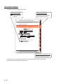
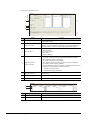
HOW TO READ THIS MANUAL
The following symbols are used in this manual.
Display reference ahead
Display of chapter finding
Referring ahead and the
reference manual have
been described by the
finger mark.
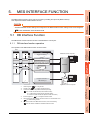
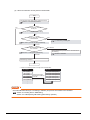
This chapter explains the system configuration available for the MES interface function.
2.1 System Configuration
2.1.1
1
OVERVIEW
SYSTEM CONFIGURATION
2
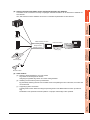
Overall system configuration
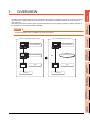
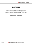
This section shows the overall system configuration when using the MES interface function.
SYSTEM
CONFIGURATION
2.
The chapter on the page which is the
opening in the index at the right of the
page is understood at one view.
SNTP server computer*1
Oracle , SQL Server
(Third party product)
Server computer
DB Connection Service
DB Connection Service Setting Tool
SPECIFICATIONS
3
Database
SETTINGS AND
PROCEDURES BEFORE USE
OF THE MES INTERFACE
FUNCTION
4
Configuration computer*1
GOT
GT Designer3
* MES interface function
* Option OS
Download
MELSECNET/H, etc.*2
*1
*2
The SNTP server computer and configuration computer can be shared as the server computer.
For controllers available for the MES interface function, refer to the following manual.
GOT1000 Series Connection Manual
*3
RS-232 or Ethernet connection is also available.
However, in Ethernet connection, the option OS cannot be installed.
5
MES INTERFACE
FUNCTION
Install
USB*3
6
MES INTERFACE
FUNCTION SETTING
Ethernet
DB CONNECTION
SERVICE AND SETTING
TOOL
7
2-1
2.1 System Configuration
TROUBLE
SHOOTING
8
Display of section and subsection title
The section and the sebsection on the
open page are understood at one view.
The figure above is for explanation purposes only, and therefore differs from the actual pages.
There are also the following types of explanations.
A - 16
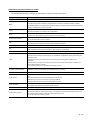
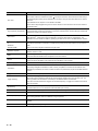
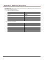
DEFINITIONS AND DESCRIPTIONS OF TERMS
The following table shows the definitions and descriptions of the terms used in this manual.
Term
Tag for Wonderware Historian
Description
Name for data unit in the database Wonderware Historian.
Abbreviation for Manufacturing Execution System
MES
The system that controls and monitors the plant status in real time to optimize production activities
This enables speed-up of the responses to production plans and status changes and efficient production
operation, optimizing the production activities.
ODBC
SNTP
SNTP server computer
SQL
UTF-8
XML
Account
Abbreviation for Open Database Connectivity
Standard specifications for software to access databases
Abbreviation for Simple Network Time Protocol
Protocol for synchronizing the time of computers via a TCP/IP network
Computer that provides time information to the GOT
This can be shared with a server computer.
Abbreviation for Structured Query Language
Data manipulation language and used for relational database operations
Method for converting character strings defined in Unicode into byte strings (Number strings)
Abbreviation for eXtensible Markup Language
Markup language for describing documentation, data meanings, and structures
Represents the right to use a GOT or a server computer, or an ID necessary for its use.
The unit for processing defined in the job. The unit for processing includes [Communication action] and
[Transmit resource action] for communicating with a database, and [Operation action] for operating tag
component values.
Action
[Communication action] is a processing unit for sending one SQL text (Select, Update, Insert,
MultiSelect).
[Transmit resource action] is the processing unit for sending each SQL text (Insert) for records in one
resource data collected in the GOT.
Up to 20 dyadic operations can be defined for [Operation action].
Application server computer
COMMIT
One of the server computers, which communicates by the MES interface function to run programs
A database computer can be shared as an application server computer.
Processing that makes a permanent change to databases
Generic term for the services that a server computer to which the DB Connection Service is installed can
offer.
Server service
There are database server service and application server service.
Database server service is a service for accessing a database.
Application server service is a service for linking with a program.
Server computer
Job
Generic term for database server computers and application server computers
This computer can be shared as an SNTP server computer.
A set of processings executed by a preset trigger
A personal computer that runs GT Designer3
Configuration computer
This is used to install the option OS into a GOT, to configure the Communication Settings, screens and
MES interface function settings, and to download projects to the GOT.
This can be shared as a server computer.
(To the next page)
A - 17
Term
Description
Standard time zone for each region of the world
Each nation uses the time difference (within
12 hours) from the time at the Greenwich Observatory in
the United Kingdom (GMT) as the standard time. The region using the same time difference is called a
Time zone
time zone.
The standard time for Japan is 9 hours ahead of the GMT.
Some nations adopt daylight-saving time in summer season in which clocks are set one hour ahead of
the standard time.
Generic term for components (Device data) making up a device tag (Tag)
Tag component (Component)
A set of data that contains the information on the GOT's internal devices, and the data type and devices
required for access to the gateway devices
Connection information necessary for accessing data using ODBC
Data source
With Windows, a data source name is assigned to connection information for manegement. The
database can be accessed via ODBC by specifying the data source name in the MES interface function.
Database (DB)
Data management method that follows relational data model logic
or
One data is expressed as a collection of multiple items (Fields) and the data collection is expressed as a
Relational
table.
database (RDB)
Data can be easily merged and selected using key data.
Database computer
Table
Device
Device tag (Tag)
One of the server computers, on which the database communicating with the GOT is run when the MES
interface function is used.
Data management format managed with relational databases
It is a two-dimensional table format composed of rows and columns.
Variety of memory data that each controller internally contains.
There are devices handled in units of bits and those handled in units of words.
Data table that contains a set of information (Components) required to access the device data in the GOT
Unit that multiple databases related to each other can be correctly processed all at once.
Transaction
Processing managed as transaction is either correctly completed or canceled with the rollback. Each
database is processed by the action, and each transaction is processed by the job with the MES interface
function.
Trigger conditions
Startup conditions for job operation
When too many trigger conditions (data transmission conditions) are met simultaneously, this function
allows the system to buffer the data and the time that trigger conditions are met to the user area. The
Trigger buffering
action (operation and transmission of the data) for the buffered data is executed later.
Even when the data transmission triggers are activated frequently, no triggers are missed so that all the
jobs are executed.
DB buffering
This function allows the system to temporarily store SQL texts that failed to be sent due to a
communication error in a CF card and to resend the texts upon recovery.
Handshake
A constant exchange of signals between the sending and receiving ends to achieve high reliability
Field
Corresponds to a column in a relational database and indicates a type of data (Record attribute).
Variable (Temporary variable)
Record
Rollback
A - 18
Variable that can be used in the same job when temporarily storing values selected from a database or
when writing operation values to a database or tag components.
Corresponds to a row in a relational database. One row (Record) stores the values of multiple columns
(Fields).
Processing for canceling changes to a database
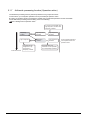
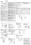
The MES interface function allows SQL text transmission from a GOT to a database in the server computer connected
via the Ethernet, enabling writing GOT's device values to the database and reading database values to set them to
GOT's devices.
This direct communication with the server computer eliminates the need for gateway equipment, realizing reduction in
the maintenance cost and improvement in reliability.
POINT
The MES interface function is available only for GT16 and GT15.
OVERVIEW
1
OVERVIEW
2
SYSTEM
CONFIGURATION
1.
3
When using MES interface function
Server (Database)
SPECIFICATIONS
When not using MES interface function
Server (Database)
Communication gateway
SETTINGS AND
PROCEDURES BEFORE USE
OF THE MES INTERFACE
FUNCTION
4
No gateway required
SQL
5
Controller
MES INTERFACE
FUNCTION SETTING
6
DB CONNECTION
SERVICE AND SETTING
TOOL
7
8
TROUBLE
SHOOTING
Controller
GOT
MES INTERFACE
FUNCTION
GOT
1-1
1.1 Features
This section explains the features of the MES interface function.
(1) Simple setting enables connection to the information system without programming.
Access to information system databases can be realized simply by making the necessary settings with the
setting tool.
Since there is no need to create programs for generating SQL texts, the engineering costs for system
construction and the work period can be reduced.
1-2
1.1 Features
(a) Buffering of send data (SQL text) during a communication error
When an error occurs during communications with a database, the SQL texts failed to be sent can be
buffered in the GOT.
After recovery, the buffered SQL texts are automatically sent to the database. (Manual operation is also
possible.)
OVERVIEW
1
(2) Important data can be protected.
2
SYSTEM
CONFIGURATION
Disconnected
Database
INSERT
3
SPECIFICATIONS
INSERT
INSERT
UPDATE
CF card
4
SETTINGS AND
PROCEDURES BEFORE USE
OF THE MES INTERFACE
FUNCTION
Recovered
Resend
Database
5
MES INTERFACE
FUNCTION
INSERT
INSERT
INSERT
UPDATE
CF card
MES INTERFACE
FUNCTION SETTING
6
DB CONNECTION
SERVICE AND SETTING
TOOL
7
TROUBLE
SHOOTING
8
1.1 Features
1-3
(b) Obtaining logs in the event of access errors
After connection to a database, if a communication error occurs, the error details can be recorded as a log
on the database side.
Analyzing the log is useful for data protection and error analysis.
Database
DB connection service
Access
log
SQL failure
log
(3) The information system load can be reduced.
Data can be monitored on the GOT and when the conditions are met, the data can be sent to the information
system.
This can reduce the information system load, compared to the case of the conventional system that constantly
samples and monitors data.
[With the MES interface function]
<Information system>
Data transmission only when needed
Conditions met
Database
[Conventional system]
<Information system>
Database
Constant sampling/monitoring from
information system is required.
(4) Access independent of the database table configuration is possible.
Freely designed database tables can be used for access to databases.
The MES interface function offers not only the high flexibility in designing a new system but also the capability of
reconstructing the existing system without changing the database tables.
1-4
1.1 Features
Controllers can be connected in a variety of topologies and their information can be stored into a database via
GOT devices.
Also, data read out from the database can be set to controllers as parameters via GOT devices.
OVERVIEW
1
(5) Various controller information can be stored and changed in the database.
SYSTEM
CONFIGURATION
2
PLC
3
SPECIFICATIONS
Inverter
<MES interface function>
Data transmission
Status monitoring function
Script function
Gateway function
Servo
Database
4
SETTINGS AND
PROCEDURES BEFORE USE
OF THE MES INTERFACE
FUNCTION
Data query
Microcomputer
MES INTERFACE
FUNCTION
5
Barcode reader
(6) Other features
Supporting system construction
The diagnostic function allows checking the operating status of the MES interface function (in real time,
log).
Modification of the job status and test operation of a project under design is also possible.
7
8
TROUBLE
SHOOTING
(c)
DB CONNECTION
SERVICE AND SETTING
TOOL
(b) Obtaining the exact time by time synchronization
By periodically obtaining the time from the SNTP server and updating the time of the GOT, the correct time
can be ensured.
MES INTERFACE
FUNCTION SETTING
6
(a) Reducing setting mistakes by use of tag names
Tag names can be assigned to devices.
Assigning recognizable tag names can reduce setting mistakes.
1.1 Features
1-5
1.2 What is the MES Interface Function?
The items listed below are used with the MES interface function.
For equipment required for the MES interface function, refer to the following:
2.3 Required Equipment, Software and Option OS
Item
Description
Reference
section
Option OS (MES Interface)
The option OS that runs on a GOT to realize the MES interface function.
Chapter 5.
MES interface function setting
This function allows the MES interface function setting in GT Designer3.
Chapter 6.
DB Connection Service
Software that runs on the server computer and links databases with the GOT.
Install the software from either of the following.
• DVD-ROM of GT Works2
• Disk3 folder in the DVD-ROM of GT Works3
Chapter 7.
DB Connection Service Setting
Tool
Software that runs on the server computer and changes the settings of the DB Connection Service.
Install the software from the DVD-ROM of GT Works3.
Chapter 7.
1-6
1.2 What is the MES Interface Function?
1
SYSTEM CONFIGURATION
OVERVIEW
2.
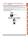
This chapter explains the system configuration available for the MES interface function.
2.1 System Configuration
SYSTEM
CONFIGURATION
2.1.1
2
Overall system configuration
This section shows the overall system configuration when using the MES interface function.
3
SNTP server computer*1
Oracle , SQL Server
(Third party product)
SPECIFICATIONS
Database
Server computer
DB Connection Service
DB Connection Service Setting Tool
SETTINGS AND
PROCEDURES BEFORE USE
OF THE MES INTERFACE
FUNCTION
4
Ethernet
Configuration computer*1
USB*3
GOT
5
GT Designer3
* MES interface function
* Option OS
MES INTERFACE
FUNCTION
Install
Download
MELSECNET/H, etc.*2
The SNTP server computer and configuration computer can be shared as the server computer.
For controllers available for the MES interface function, refer to the following.
*3
RS-232 or Ethernet connection is also available.
However, in Ethernet connection, the option OS cannot be installed.
MES INTERFACE
FUNCTION SETTING
6
*1
*2
2.2 Connection between GOT and Controllers
DB CONNECTION
SERVICE AND SETTING
TOOL
7
TROUBLE
SHOOTING
8
2.1 System Configuration
2-1
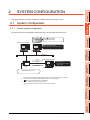
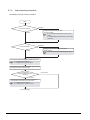
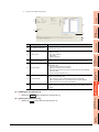
2.1.2
System configuration when installing software used for the MES Interface
Function
The following shows system configuration when installing software used for the MES interface function.
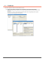
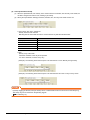
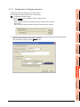
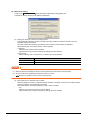
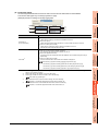
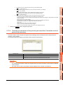
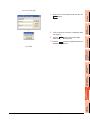
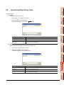
(1) When installing the DB Connection Service and DB Connection Service Setting Tool on a server
computer
Sever computer
GT Works3
Install
DB Connection Service
DB Connection Service Setting Tool
Commercial product
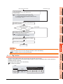
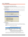
POINT
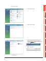
(1) When installing DB Connection Service on a database server computer, the ODBC setting for the database
used must be made beforehand.
7.2 Setting ODBC of Database
(2) When installing DB Connection Service on an application server computer, an account for user program
execution must be created beforehand.
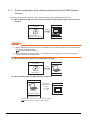
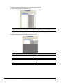
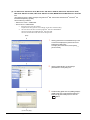
(2) When installing GT Designer3 on a configuration computer
Configuration computer
GT Works3
Install
GT Designer3
Commercial product
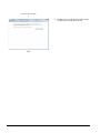
(3) When installing Option OS (MES Interface) on the GOT
Computer
Option OS
(MES interface)
Install*1
GT Designer3
+
MES interface function
Commercial product
*1
For equipment used for installation, refer to the following manual:
GT Works3 Version1 Installation Procedure Manual
2-2
2.1 System Configuration
GOT
1
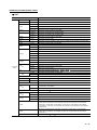
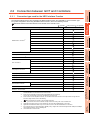
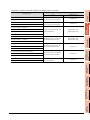
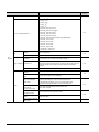
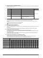
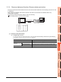
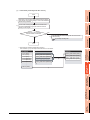
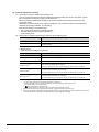
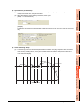
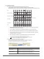
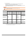
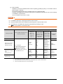
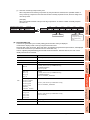
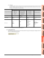
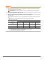
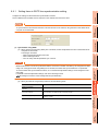
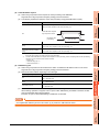
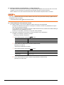
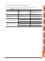
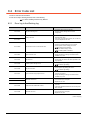
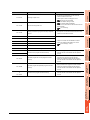
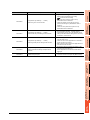
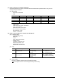
2.2 Connection between GOT and Controllers
OVERVIEW
Connection type used for the MES Interface Function
The following table shows the GOT supporting the MES interface function and availability in each connection type.
For system configuration when using the MES interface function, refer to the following manual:
GOT1000 Series Connection Manual for GT Works3 and a controller used
: Partly restricted
: Not applicable
SYSTEM
CONFIGURATION
: Applicable
2
GT16*8/GT15
Connection type
Bus connection
Direct CPU connection
Computer link connection
3
Ethernet connection*7
MELSECNET/H connection (PLC to PLC network)
MELSECNET/10 connection (PLC to PLC network)
SPECIFICATIONS
Mitsubishi PLC connection*4
*1
CC-Link IE controller network connection
CC-Link IE field network connection
CC-Link connection (Intelligent device station)
*2
4
Inverter connection
*3
Servo amplifier connection
*3
SETTINGS AND
PROCEDURES BEFORE USE
OF THE MES INTERFACE
FUNCTION
CC-Link connection (via G4)
Robot controller connection*5
Serial connection
5
MELSECNET/10 connection (PLC to PLC network)
*1
CC-Link connection (Intelligent device station)
*2
MES INTERFACE
FUNCTION
Ethernet connection*7
CNC connection*6
Serial connection
Third party PLC connection
Ethernet connection*7
Third party safety controller connection
6
MES INTERFACE
FUNCTION SETTING
Third party servo amplifier connection
Third party robot controller connection
Third party temperature controller connection
Serial connection
Microcomputer connection
Ethernet connection*7
MODBUS/RTU connection
7
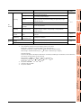
*1
*2
*3
*4
*5
*6
*7
*8
DB CONNECTION
SERVICE AND SETTING
TOOL
MODBUS/TCP connection
For the MELSECNET/10 connection, use the MELSECNET/H communication unit.
The MELSECNET/10 communication unit cannot be used.
For the CC-Link connection, use the CC-Link communication unit (GT15-J61BT13).
The CC-Link communication unit (GT15-75J61BR13-Z) cannot be used.
For the inverter or servo amplifier connection, use the status observation function or the script function to assign devices.
For how to assign devices, refer to the following:
2.2.2 Precautions for inverter or servo amplifier connection
Including connection to the motion controller CPU (Q series and A series), CNC C70, and CRnQ-700
Applicable to the CRnD-700 only. For the CRnQ-700, refer to the above Mitsubishi PLC connection.
Applicable to the MELDAS C6/C64 only. For the CNC C70, refer to the above Mitsubishi PLC connection.
For connecting GT16 to a device supporting 10BASE(-T/2/5), configure the network that supports both 10Mbps and 100Mbps
communication speeds by using a switching hub.
The GT1665HS-V cannot be used.
2.2 Connection between GOT and Controllers
2-3
8
TROUBLE
SHOOTING
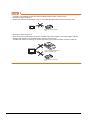
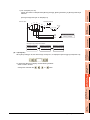
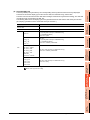
2.2.1
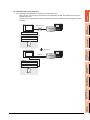
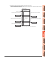
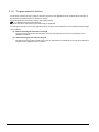
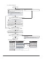
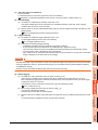
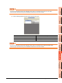
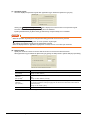
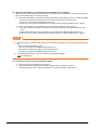
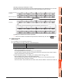
POINT
Connection type examples for the case where the MES interface function cannot be used
(Example 1) When using GT11
Because the Ethernet communication unit is not mountable, the MES interface function cannot be used.
GT11
Ethernet communication
unit
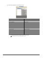
(Example 2) When using GT15
Since the CC-Link communication unit (GT15-75J61BR13-Z) is not mountable concurrently together with the
Ethernet communication unit, the MES interface function cannot be used.
To utilize both of them concurrently, use another type of the CC-Link communication unit (GT15-J61BT13).
CC-Link communication unit
(GT15-75J61BR13-Z)
GT15
Ethernet communication
unit
2-4
2.2 Connection between GOT and Controllers
1
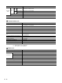
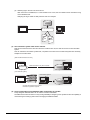
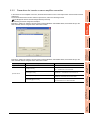
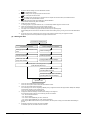
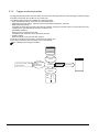
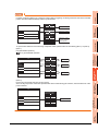
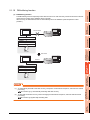
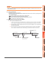
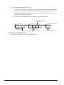
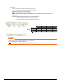
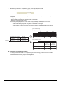
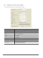
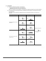
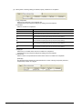
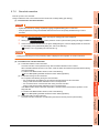
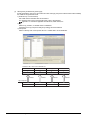
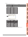
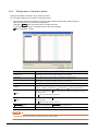
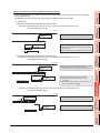
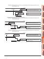
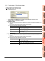
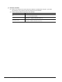
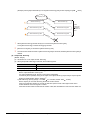
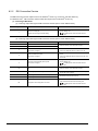
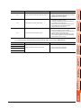
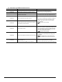
Precautions for inverter or servo amplifier connection
2
SYSTEM
CONFIGURATION
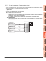
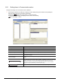
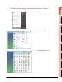
In the inverter or servo amplifier connection, the status observation function or the script function must be used for device
assignment.
For the status observation function and the script function, refer to the following manual.
GT Designer3 Version1 Screen Design Manual (Functions)
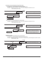
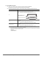
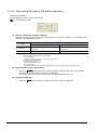
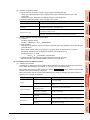
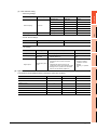
The following are device assignment examples.
Example 1) Setting for assigning devices of the inverter [FREQROL 500/700/800 Series, Sensorless servo] to the
GOT's internal devices using the status observation function
OVERVIEW
2.2.2
SPECIFICATIONS
3
SETTINGS AND
PROCEDURES BEFORE USE
OF THE MES INTERFACE
FUNCTION
4
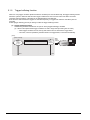
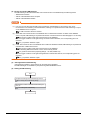
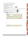
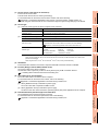
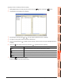
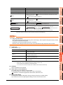
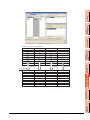
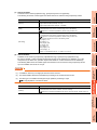
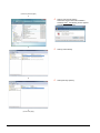
Example 2) Setting for assigning devices of the inverter [FREQROL 500/700/800 Series, Sensorless servo] to the
GOT's internal devices using the status observation function
5
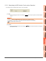
ON Device GB40
Ordinary (GB40 is always ON.)
[w:GD0]=[0-0:w:A0];
Assigns devices A0 to A15 of the inverter that has channel
No. 1 and station No. 0 to device GD0.
[w:GD10]=[0-0:w:Pr0];
Assigns devices Pr 0 to Pr 15 of the inverter that has
channel No. 1 and station No. 0 to device GD 10.
[w:GD20]=[0-0:w:PG0];
Assigns devices PG0 to PG15 of the inverter that has
channel No.1 and station No.0 to device GD20.
[w:GD31600]=[@3:0-16:w:A0];
Assigns devices A0 to A15 of the inverter that has channel
No.3 and station No.16 to device GD31600.
6
7
DB CONNECTION
SERVICE AND SETTING
TOOL
Operation device
MES INTERFACE
FUNCTION
Remarks
8
TROUBLE
SHOOTING
Trigger
Setting content
MES INTERFACE
FUNCTION SETTING
Setting item
2.2 Connection between GOT and Controllers
2-5
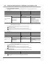
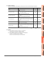
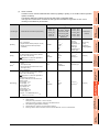
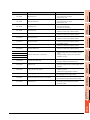
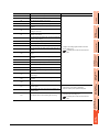
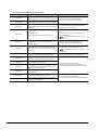
2.3 Required Equipment, Software and Option OS
(1) Required equipment and software
The following table lists the equipment and software required for use of the MES interface function.
(a) GT16
Application
Required equipment/software
Module name
Executing the MES interface function on the GOT
Option function board
GT16-MESB
Connecting the GOT to Ethernet
Built-in Ethernet interface
-
Connecting the GOT to controllers
Setting the MES interface function
Setting the MES interface
function
DB buffering function,
log output function,
diagnostics function
GOT1000 Series Connection Manual for GT Works3 and a controller used
GT Designer3 Version1.00A or later
(MES interface function)
CF card
GT05-MEM-128MC,
GT05-MEM-256MC,
GT05-MEM-512MC,
GT05-MEM-1GC, GT05-MEM-2GC,
GT05-MEM-4GC, GT05-MEM-8GC,
GT05-MEM-16GC, Commercially
available CF card (128MB or more)*1
*1
Some models with the operations checked by our company are usable.
For the validated models, refer to Technical News GOT-A-0010 "List of Valid Devices Applicable for GOT1000 Series" separately
available, or contact your local distributor.
For installation of the required equipment, refer to the following manual.
GT16 User's Manual
For connection of the required equipment, refer to the following manual.
GOT1000 Series Connection Manual for GT Works3 and a controller used
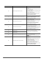
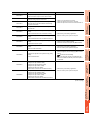
(b) GT15
Application
Required equipment/software
Module name
Executing the MES interface function on the GOT
Option function board
GT15-MESB48M
Connecting the GOT to Ethernet
Ethernet communication unit
GT15-J71E71-100
Connecting the GOT to controllers
Setting the MES interface function
Setting the MES interface
function
*1
DB buffering function,
log output function,
diagnostics function
GOT1000 Series Connection Manual for GT Works3 and a controller used
GT Designer3 Version1.00A or later
(MES interface function)
CF card
GT15-MEM-128MC
GT15-MEM-256MC
Commercially available CF card (128MB
to 2GB)*1
Some models with the operations checked by our company are usable.
For the validated models, refer to Technical News GOT-A-0010 "List of Valid Devices Applicable for GOT1000 Series" separately
available, or contact your local distributor.
For installation of the required equipment, refer to the following manual.
GT15 User's Manual
For connection of the required equipment, refer to the following manual.
GOT1000 Series Connection Manual for GT Works3 and a controller used
(2) Required option OS
The following shows the option OS required for use of the MES interface function.
Application
MES interface function
OS name
MES Interface
For installation of the required option OS, refer to the following manual.
GT Designer3 Version1 Screen Design Manual (Fundamentals)
2-6
2.3 Required Equipment, Software and Option OS
1
2.4 Operating Environment
Configuration computer
OVERVIEW
2.4.1
The operating environment for the configuration computer is identical to those for GT Designer3.
For the operating environment for GT Designer3, refer to the following manual.
GT Designer3 Version1 Screen Design Manual (Fundamentals)
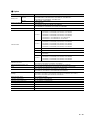
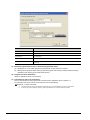
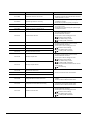
Server computer (SNTP server computer)
SYSTEM
CONFIGURATION
2.4.2
2
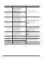
This section explains the operating environment for the server computer.
Item
Description
Personal computer
A computer on which the following operating systems can run
3
Microsoft Windows Server 2012 R2 *11*12*16*17*18*19*20
Microsoft Windows Server 2012 *11*12*16*17*18*19*20
SPECIFICATIONS
Microsoft Windows Server 2008 R2 *11*12*16
Microsoft Windows Server 2008 *11*12*16
Microsoft Windows Server 2003 x64 Edition *4*5
Microsoft Windows Server 2003 *4*5
Microsoft Windows 2000 Server Service Pack2 or later *4
Microsoft Windows 8.1 Enterprise *5*11*12*17*18*19*20
4
SETTINGS AND
PROCEDURES BEFORE USE
OF THE MES INTERFACE
FUNCTION
Microsoft Windows 8.1 pro *5*11*12*17*18*19*20
Microsoft Windows 8 Enterprise *5*11*12*17*18*19*20
OS(English version)
Microsoft Windows 8 pro *5*11*12*17*18*19*20
Microsoft Windows 7 Ultimate *5*11*12*15*17
Microsoft Windows 7 Enterprise *5*11*12*15*17
Microsoft Windows 7 Professional *5*11*12*15*17
Microsoft Windows Vista Ultimate *4*5*11*12
5
Microsoft Windows Vista Enterprise *4*5*11*12
Microsoft Windows Vista Business *4*5*11*12
MES INTERFACE
FUNCTION
Microsoft Windows XP Professional *2*4*5
Microsoft Windows 2000 Professional Service Pack2 *4
CPU
Required memory
See "Performance required for personal computer and operating system to be used" below.
Free hard disk space
64MB or more (After database installation)
Disk drive
DVD-ROM drive
Display
A display where the above OS and after-mentioned databases can run
Interface
Ethernet
6
MES INTERFACE
FUNCTION SETTING
Computer
DB CONNECTION
SERVICE AND SETTING
TOOL
7
TROUBLE
SHOOTING
8
2.4 Operating Environment
2-7
Item
Description
When using the DB interface function: Relational database (any of the following)
• Oracle 12c*3
• Oracle 11g*2
• Oracle 10g*1
• Oracle 9i*1
• Oracle 8i*1
• Microsoft SQL Server 2012*2*6*7
• Microsoft SQL Server 2008 R2*2*6*7
• Microsoft SQL Server 2008*2*6*7
• Microsoft SQL Server 2005*1*6
Software
• Microsoft SQL Server 2000*1*6
• Microsoft SQL Server 2000 Desktop Engine(MSDE 2000)*6
• Microsoft Access 2010*1*7*13*14
• Microsoft Access 2007*7*13*14
• Microsoft Access 2003*7*8
• Microsoft Access 2000*7*8
• Wonderware Historian 9.0*9*10
When using the SNTP time synchronization function: SNTP server
(Equipped as a standard to Windows 2000 Server, Windows Server 2003)
Others
The mouse, keyboard, and DVD-ROM driver must be compatible with the above OS.
*1
*2
*3
*4
*5
Only 32-bit is available.
32-bit and 64-bit are available.
Only 32-bit is available.
To install or operate DB Connection Service or DB Connection Service Setting Tool, the administrator authority is required.
The following functions are not available.
If any of the following functions is used, this product many not operate normally.
•
•
•
•
Activating the application with Windows compatibility mode
Fast user switching
Change your desktop themes (fonts)
Remote desktop
• DPI setting other than the normal size (For Windows XP, Windows Vista, Windows Server 2003)
*6
*7
*8
*9
*10
*11
*12
*13
*14
*15
*16
*17
*18
*19
*20
2-8
• Setting the size other than [Smaller - 100%] for the characters and images on the screen (For Windows 7, Windows 8)
Set [SQL Server and Windows] for the security authentication mode.
Up to 127 fields can be updated for a communication action.
Do not access the same file with multiple GOTs and MES interface modules simultaneously.
Only [Insert] can be used for the communication action.
The rollback cannot be used for inserting data to a database.
15GB or more of free space is required.
A standard user account or above is required.
Memo-type fields in Rich Text Format cannot be used.
A field having multiple values cannot be used.
Windows XP Mode is not supported.
Server Core installation is not supported. Be sure to perform a full installation.
Windows Touch and Touch are not supported.
Modern UI style is not supported.
Hyper-V is not supported.
It is necessary to install .NET FrameWorks3.5.
When the Windows8 or Windows Server 2012 is used, it is necessary to activation [.NET FrameWorks3.5(including .NET2.0 and
.NET3.0)] in the control panel at [Disable or Enable the Windows function]
2.4 Operating Environment
1
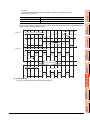
Performance required for personal computer and operating system to be used
Microsoft Windows XP Professional
Microsoft Windows 2000 Professional
Microsoft Windows Server 2003
Microsoft Windows 2000 Server
CPU
Required memory
Intel Pentium /Celeron series CPU
with clock speed of at least 300 MHz
512 MB or more
OVERVIEW
Performance required for personal computer
Intel Pentium /Celeron series CPU
with clock speed of at least 550 MHz
1GB or more
2
Intel Core2 Duo series CPU with clock
speed of at least 2GHz
64bit OS:2GB or more
32bit OS:1GB or more
Intel Pentium /Celeron series CPU
with clock speed of at least 1GHz
64bit OS:2GB or more
32bit OS:1GB or more
Intel Pentium /Celeron series CPU
with clock speed of at least 1GHz
1GB or more
Intel Pentium /Celeron series CPU
with clock speed of at least 2GHz
2GB or more
Intel Core2 Duo series CPU with clock
speed of at least 2GHz
2GB or more
SYSTEM
CONFIGURATION
Operating system
Microsoft Windows 8 Enterprise
Microsoft Windows 8 pro
Microsoft
Windows
8 Enterprise
Microsoft Windows 8 pro
3
Microsoft Windows 7 Enterprise
SPECIFICATIONS
Microsoft Windows 7 Ultimate
Microsoft Windows 7 Professional
Microsoft Windows Vista Ultimate
Microsoft Windows Vista Enterprise
4
Microsoft
Microsoft
Windows
Server
2003 x64 Edition
Windows
Server
2008 R2
SETTINGS AND
PROCEDURES BEFORE USE
OF THE MES INTERFACE
FUNCTION
Microsoft Windows Vista Business
Microsoft Windows Server 2008
5
MES INTERFACE
FUNCTION
Microsoft Windows Server 2012
6
MES INTERFACE
FUNCTION SETTING
7
DB CONNECTION
SERVICE AND SETTING
TOOL
8
TROUBLE
SHOOTING
Microsoft Windows Server 2012 R2
2.4 Operating Environment
2-9
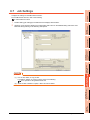
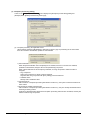
POINT
How to set security authentication mode (SQL Server and Windows)
(1) For Microsoft SQL Server 2012, Microsoft SQL Server 2008 R2, Microsoft SQL Server 2008, Microsoft
SQL Server 2005 and Microsoft SQL Server 2000.
Set the security authentication mode in the SQL Server Properties (Configure) screen.
(2) For Microsoft SQL Server 2000 Desktop Engine (MSDE 2000)
When installing MSDE2000, specify a command parameter.
setup sapwd = "sa" SECURITYMODE=SQL
(sa: Specify an arbitrary password.)
2 - 10
2.4 Operating Environment
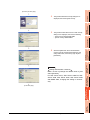
1
2.1 Cautions on System Configuration
OVERVIEW
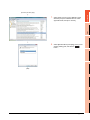
(1) Relational databases that support the MES interface function
For the relational databases that support the MES interface function, refer to the following:
2.4.2 Server computer (SNTP server computer)
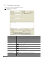
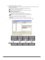
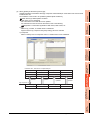
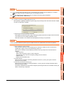
(2) Notes when CF card is used
2
SYSTEM
CONFIGURATION
Insert the memory card into the A drive of the GOT.
SPECIFICATIONS
3
SETTINGS AND
PROCEDURES BEFORE USE
OF THE MES INTERFACE
FUNCTION
4
MES INTERFACE
FUNCTION
5
MES INTERFACE
FUNCTION SETTING
6
DB CONNECTION
SERVICE AND SETTING
TOOL
7
TROUBLE
SHOOTING
8
2.1 Cautions on System Configuration
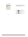
2 - 11
The CF card cannot be used in B drive.
2 - 12
2.1 Cautions on System Configuration
1
SPECIFICATIONS
OVERVIEW
3.
This chapter explains the performance specifications, functions and devices of the MES interface function.
3.1 Performance Specifications
SYSTEM
CONFIGURATION
2
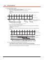
The following are the performance specifications of the MES interface function.
SPECIFICATIONS
3
SETTINGS AND
PROCEDURES BEFORE USE
OF THE MES INTERFACE
FUNCTION
4
MES INTERFACE
FUNCTION
5
MES INTERFACE
FUNCTION SETTING
6
DB CONNECTION
SERVICE AND SETTING
TOOL
7
TROUBLE
SHOOTING
8
3.1 Performance Specifications
3-1
Item
Specifications
No. of connected databases
Reference
section
Up to 8 databases/project
• Oracle 12c*5
• Oracle 11g*4
• Oracle 10g*3
• Oracle 9i*3
• Oracle 8i*3
• Microsoft SQL Server 2012*4
• Microsoft SQL Server 2008 R2*4
• Microsoft SQL Server 2008*4
• Microsoft SQL Server 2005*3
No. of connectable databases
6.6.1
• Microsoft SQL Server 2000*3
• Microsoft SQL Server 2000 Desktop Engine(MSDE 2000)
• Microsoft Access 2013*3
• Microsoft Access 2010*4
• Microsoft Access 2007
• Microsoft Access 2003
• Microsoft Access 2000
• Wonderware Historian 9.0
Job
DB
interface
trigger conditions
Action
Allowable number of
settings
Up to 64 jobs/project
Trigger buffering
Up to 128 tag components/tag
No. of conditions can be
combined
Up to 2 conditions
• (Combination can be selected either AND or OR)/job
Condition type
20 types (Time specification (6 types), Specified time period, comparison
between tag component values (6 types), comparison between tag component
value and constant value (6 types), At module startup) and Handshake
operation
Validation interval
One second at the minimum
Allowable number of
settings
Up to 10 actions/job
Communication action
type
4 types (Select, Update, Insert, MultiSelect)
No. of communication
action fields
Up to 8192 fields/project
• [DB-Tag link setting]: Up to 256 rows/communication action
• [Select/Update conditions]: Up to 8 rows/communication action
• [Select sort settings]: Maximum 8 rows/communication action
6.7.1
6.7.2
6.8
No. of records/data
selectable for
communication action
Up to 40000 records/MultiSelect communication action
Up to 45000 words/job
No. of operations possible
for operation action
(Up to 20 dyadic operations)/operation action
Operators for operation
action
6 types (Addition, subtraction, multiplication, division, remainder, character
string combination)
No. of resource data send
action fields
Maximum 8192 fields/project
6.8.1
6.8.2
6.8.3
(To the next page)
3-2
3.1 Performance Specifications
Up to 64 tags/project
No. of tag components
Up to 256 tag components/tag
Up to 4096 tag components/project
Data type
5 types (Signed single-precision integer type (16 bits), signed double-precision
integer type (32 bits), single-precision floating point type (32 bits), bit type,
character string type)
2
6.5.3
Character string length
Up to 32 characters
No. of statistical
processings
Up to 64 tag components
6 types
Device tag
(Average, maximum, minimum, moving average*1, moving maximum*1,
Statistical processing
moving minimum*1)
DB buffering
(Once before execution of the initial action + once after execution of the final
action)/job
6.7.3
Buffering capacity for
Maximum capacity: CF card capacity -32M bytes
(16 Mbytes to 512 Mbytes)
6.9.2
communication errors*2
Log capacity for MES interface function
execution
Maximum capacity: 1 Mbyte (CF card)
Log capacity for job execution events
Maximum capacity: 2 Mbytes (CF card)
*1
*2
3
6.11
4
[No. of samples] can be set up to 20.
How to estimate the buffering time from the buffering capacity is shown below.
Buffering time = (Allowable No. of bufferings)
(Frequency [times/hour]) [h]
Allowable No. of bufferings = (Capacity to be used)
(SQL text length + Overhead (4 bytes)
SQL text length = Total field character length + 6
No. of fields + Total data length + 20 [bytes]
[Calculation Example]
In the case of the capacity of 64 Mbytes, the field name of 16 characters, the data length of 32 characters, access to 256 fields by
one action per job, and executing once per 30 seconds
30
60)
256) = 13844 [bytes]
1024)
(13844 + 4)
MES INTERFACE
FUNCTION
*3
*4
*5
Buffering time = 4846
(60
Only 32-bit is available.
32-bit and 64-bit are available.
Only 64-bit is available.
256 + (32
1024
4846
40 [h]
6
MES INTERFACE
FUNCTION SETTING
256) + 6
Allowable No. of bufferings = (64
7
DB CONNECTION
SERVICE AND SETTING
TOOL
SQL text length = (16
5
8
TROUBLE
SHOOTING
Working
log
Allowable number of
settings
SPECIFICATIONS
Program
execution
1
SYSTEM
CONFIGURATION
DB
interface
No. of tags
Reference
section
SETTINGS AND
PROCEDURES BEFORE USE
OF THE MES INTERFACE
FUNCTION
Device tag
Specifications
OVERVIEW
Item
3.1 Performance Specifications
3-3
3.2 GOT Devices Available for the MES Interface
Function
The following are GOT devices that can be set in the Device tag settings of the MES interface function.
Type
Description
Available setting range
GOT bit register
Bit register inside the GOT
Can be used as a bit device.
GOT data register
Data register inside the GOT
Can be used as a word device.
GD0 to GD65535
GOT special
register
Special register inside the GOT
Stores GOT's internal information, communication status, error information, etc.
Can be used as a word device.
GS0 to GS1023*2
Gateway device
Used when making interaction between the MES interface function and the gateway function.
Virtual device for indirectly reading or writing the controller devices that are monitored by another GOT.
Can be used as a word device.
*1
For GB0 to GB63, refer to the following manual.
*2
Do not write any value to a write-prohibited GOT special register.
Setting a value to the GOT special register may affect the GOT operation.
For the GOT special register, refer to the following manual.
*3
Specify the gateway device in the following format.
(Network No.) - (Station No.) : EG (Device No.)
Network No. : 1 to 239
Station No. : 1 to 64
Device No. : 0 to 32767
GT Designer3 Version1 Screen Design Manual (Fundamentals)
GT Designer3 Version1 Screen Design Manual (Fundamentals)
POINT
The gateway function setting is required for use of the gateway devices.
For the gateway setting, refer to the following manual.
GOT1000 Series Gateway Functions Manual for GT Works3
3-4
3.2 GOT Devices Available for the MES Interface Function
GB64 to GB65535*1
1-1: EG0 to 239-64:
EG32767*3
1
3.3 Function List and Setting Item List
OVERVIEW
This section provides the lists of the functions and setting items that can be set for the MES interface function.
(1) MES interface function list
Executes communication with the database in units of jobs.
Reference
section
5.1
6.7
6.8
2
SYSTEM
CONFIGURATION
DB interface function
Description
Tag function
Collects data in the internal devices or gateway devices of the GOT on the network in units of tags.
Assigning a database field to a tag component allows reading or writing of a database value or
device data that is specified by the tag component.
5.1.3
6.5
Trigger monitoring function
Monitors values such as the time and tag values and, when the trigger condition changes from false
to true (when the conditions are met), starts a job.
5.1.4
6.7.2
Trigger buffering function
Allows the system to buffer the data and the time that trigger conditions are met to the user area of
the GOT when too many trigger conditions (data transmission conditions) are met simultaneously.
The action (operation and transmission of the data) for the buffered data is executed later.
Even when the data transmission triggers are activated frequently, no triggers are missed so that all
the jobs are executed.
5.1.5
6.7.1
SQL text transmission
(Communication action)
Automatically creates an SQL text and communicates with the database.
The following three types of commands can be selected for the SQL text.
• Select/MultiSelect
• Update
• Insert
5.1.6
6.8.1
Arithmetic processing
function
(Operation action)
Allows operations of tag component values.
5.1.7
6.8.2
Resource data send
function (Resource data
send action)
Sends the resource data collected in the GOT to the database.
A SQL text (INSERT) is used for sending the resource data to the database.
5.1.8
6.8.3
Program execution
function
Executes programs in the application server computer before execution of the first action and after
execution of the last one in a job.
5.1.9
6.7.3
DB buffering function
Temporarily stores SQL texts into a CF card when they cannot be sent due to network disconnection
or failure of the database server computer.
After recovery, the buffered SQL texts are automatically sent to the database. (Manual operation is
also possible.)
5.1.10
6.9.2
6.10.4
6.10.5
SNTP time synchronization
function
Allows the time on the GOT to be synchronized with the time on the SNTP server computer on the
network.
5.2
6.9.1
Diagnostics function
Used to stop/restart the MES interface function, check job operations and configure the settings.
6.10
SPECIFICATIONS
3
SETTINGS AND
PROCEDURES BEFORE USE
OF THE MES INTERFACE
FUNCTION
4
5
MES INTERFACE
FUNCTION
Function
7.1
Executes the operation requested by the DB interface function or returns a response.
7.2
Connection setting
function
Restricts IP addresses of GOTs that can be connected to the database.
7.5
Log output function
Outputs the execution status of DB Connection Service to the log.
7.8
7
8
TROUBLE
SHOOTING
DB server function
DB CONNECTION
SERVICE AND SETTING
TOOL
Allows direct access to a database upon request of the DB interface function.
ODBC connection function
MES INTERFACE
FUNCTION SETTING
6
3.3 Function List and Setting Item List
3-5
(2) List of the MES interface setting items
Function
Device tag settings
Description
Configure the settings for the tag function.
Reference
section
6.5
Array setting
Configure this setting when writing multiple records extracted from a database to the same tag
component.
6.5.2
Component setting
Configure the settings for assigning GOT devices to tags.
6.5.3
Server service settings
Configure the settings for access to a server computer.
Job settings
Configure the settings for the DB interface function.
6.6
6.7
trigger conditions
Configure the settings for startup conditions of the job.
6.7.2
Trigger buffering
Set whether to utilize the trigger buffering function or not.
6.7.1
Communication action
Configure the settings for communications with a database.
6.8.1
Operation action
Configure the settings for operation of tag component values.
6.8.2
Resource data send action
Configure the settings for sending the resource data to the database.
6.8.3
program execution
Configure the settings for the program execution function.
6.7.3
DB buffering
Set whether to utilize the DB buffering function or not.
6.7.4
One-shot execution
Execute a job as a one-shot task.
6.7.6
Option setting
Configure the SNTP time synchronization setting and the DB buffering function setting.
6.9
SNTP time
synchronization setting
Configure the settings for the SNTP time synchronization function.
6.9.1
DB buffering setting
Configure the settings for the DB buffering function.
6.9.2
Perform the remote diagnosis for the MES Interface function.
6.10
diagnosis
Status
The operation status of the option OS (MES Interface) can be checked.
6.10.1
Operation
The operation status of the MES Interface function can be checked.
6.10.2
Change Job Status
The job status can be changed.
6.10.3
Connection result of
previous job execution
Connection with the server computer set in [Server Service setting], which is made at the time of the
previous job execution, can be displayed.
6.10.4
DB buffering operation
The DB buffering can be operated.
6.10.5
MESI/F Log
Displays the working log of the MES Interface function.
6.11
MES Interface Execute
Log
Displays the MES Interface function execution log.
6.11.1
Job Execute Log
Displays the job execution event log.
6.11.2
(3) List of setting items of DB Connection Service Setting Tool
Function
3-6
Description
Service port
Specify the number of the port where the DB Connection Service operates.
DB access timeout
Set a timeout time (unit: seconds) used when no response may be returned after requesting program
execution or value writing/reading from the GOT to a database.
IP address setting
Determine whether or not to restrict IP addresses of GOTs whose connection to DB Connection
Service is permitted.
Output access log
Set whether or not to output the access log.
Output SQL failed log
Set whether or not to output the SQL failure log.
3.3 Function List and Setting Item List
Reference
section
7.5
1
3.4 GOT Internal Device (GS)
OVERVIEW
GOT internal device list
The list of the GOT internal devices (GS) used for the MES interface module is shown below.
(2) Values stored in the GOT internal devices (GS) are cleared to 0 when the GOT is powered OFF and then ON
or is reset.
266 to 272
273
MES interface
function
area
274
275
SNTP time synchronization setting status
1: [Synchronize with SNTP]
0: [SNTP time synchronization setting not exist/failed]
0
SNTP time query result
0
Use prohibited
-
3.4.2
4
-
Monitoring interval timeout count
0
670
No. of trigger buffer data
0
671
Trigger buffer overflow count
0
Trigger buffer overflow flag for a job
0
672 to 675
3.4.2
Reference
section
SETTINGS AND
PROCEDURES BEFORE USE
OF THE MES INTERFACE
FUNCTION
265
Initial
value
Name
3.4.2
5
MES INTERFACE
FUNCTION
Application
MES Interface Function area
This section explains the details of the special registers used for the MES interface function.
(1) SNTP time synchronization setting status (GS265)
6
(a) The setting status of the SNTP time synchronization setting is stored.
For the SNTP time synchronization setting, refer to the following.
6.9.1 Setting items in SNTP time synchronization setting
0: [SNTP time synchronization setting not exist/failed]
1: [Synchronize with SNTP]
(b) When the "Synchronize using SNTP" box is checked in the Option setting
This area is set when the clock time information was obtained from the SNTP server computer.
If it could not be obtained from the SNTP server computer, this area is not set since the operation for
selection of [Synchronize with PLC CPU time] is performed (The time is synchronized with the time of the
PLC CPU).
MES INTERFACE
FUNCTION SETTING
GS
3
SPECIFICATIONS
(1) For details of any other GOT internal devices (GS) than the shown areas used for the MES interface function,
refer to the following manual.
GT Designer3 Version1 Screen Design Manual (Fundamentals)
SYSTEM
CONFIGURATION
2
POINT
7
DB CONNECTION
SERVICE AND SETTING
TOOL
3.4.1
TROUBLE
SHOOTING
8
3.4 GOT Internal Device (GS)
3-7
(2) SNTP time query result (GS266 to GS272)
When the "Synchronize using SNTP" box is checked in in the Option setting, the time information obtained from
the SNTP server is stored.
GS
Name
Description
266
SNTP time query result (Year)
The four-digit year data is stored.
267
SNTP time query result (Month)
The month data, 01 to 12, is stored.
268
SNTP time query result (Day)
The day data, 01 to 31, is stored.
269
SNTP time query result (Hour)
The hour data, 00 to 23, is stored.
270
SNTP time query result (Minute)
The minute data, 00 to 59, is stored.
271
SNTP time query result (Second)
The second data, 00 to 59, is stored.
SNTP time query result (Day of the week)
The day-of-the-week data is stored.
0: Sunday 1: Monday 2: Tuesday
3: Wednesday 4: Thursday 5: Friday
6: Saturday
272
Setting side
Set by the system
(3) Monitoring interval timeout count (GS275)
The cumulative number of times that a monitoring interval timeout has occurred is stored.
If monitoring interval timeout occurs frequently, check the number of job settings and the trigger condition
setting.
For the monitoring interval timeout, refer to the following:
Appendix2 About Monitoring Interval Timeout
(4) No. of trigger buffer data (GS670)
The number of trigger buffer data is stored.
When many trigger buffer data is stored for a long time, the GOT becomes busy. As a result, some data may not
be collected.
Check the number of job settings for which [Trigger buffering] is enabled and the trigger condition setting.
(5) Trigger buffer overflow count (GS671)
The cumulative number of times that a trigger buffer overflow has occurred is stored.
The trigger buffer overflow means that 129th trigger data is discarded without being buffered when 128 trigger
data is already buffered.
If trigger buffer overflow occurs frequently, check the number of job settings for which [Trigger buffering] is
enabled and the trigger condition setting.
(6) Trigger buffer overflow flag for a job (GS672 to GS675)
The flag indicates the status of trigger buffer overflow for each job.
When a trigger buffer overflow occurs for a job, the internal device corresponding to the job turns ON.
The following table shows the internal devices that are corresponding to jobs 1 to 64.
Name
Job and internal device
GS672
b0
b1
b2
b3
b4
b5
b6
b7
b8
b9
b10
b11
b12
b13
b14
b15
Jobs 1 to 16
1
2
3
4
5
6
7
8
9
10
11
12
13
14
15
16
GS673
b0
b1
b2
b3
b4
b5
b6
b7
b8
b9
b10
b11
b12
b13
b14
b15
Jobs 17 to 32
17
18
19
20
21
22
23
24
25
26
27
28
29
30
31
32
GS674
b0
b1
b2
b3
b4
b5
b6
b7
b8
b9
b10
b11
b12
b13
b14
b15
Jobs 33 to 48
33
34
35
36
37
38
39
40
41
42
43
44
45
46
47
48
GS675
b0
b1
b2
b3
b4
b5
b6
b7
b8
b9
b10
b11
b12
b13
b14
b15
Jobs 49 to 64
49
50
51
52
53
54
55
56
57
58
59
60
61
62
63
64
3-8
3.4 GOT Internal Device (GS)
1
OVERVIEW
SETTINGS AND PROCEDURES
BEFORE USE OF THE MES
INTERFACE FUNCTION
2
SYSTEM
CONFIGURATION
4.
This chapter explains the procedures and settings to be done before use of the MES interface function.
4.1 Settings and Procedures before Use of the MES
Interface Function
3
SPECIFICATIONS
The flowcharts for use of the MES interface function are shown here.
POINT
Start the server computer, and then the GOT.
4
SETTINGS AND
PROCEDURES BEFORE USE
OF THE MES INTERFACE
FUNCTION
(1) Starting the server computer
Procedure before operation
5
Server computer/SNTP server computer
Application server computer *2
SNTP server computer *3
MES INTERFACE
FUNCTION
Database server computer *1
Start up the SNTP server.
Create a user program. *5
Set the ODBC of the database.
Create an account for user program
execution. *6
6
MES INTERFACE
FUNCTION SETTING
Install a relational database and design
a table. *4
7.2 Setting ODBC of Database
Perform login check with the account
for user program execution. *7
Install DB Connection Service and
DB Connection Service Setting Tool.
4.2 Installation and Uninstallation
4.2 Installation and Uninstallation
Change the settings of DB Connection
Service.
7.1 DB Connection Service Functions
7
DB CONNECTION
SERVICE AND SETTING
TOOL
Install DB Connection Service and
DB Connection Service Setting Tool.
Change the settings of DB Connection
Service.
8
7.1 DB Connection Service Functions
4.1 Settings and Procedures before Use of the MES Interface Function
TROUBLE
SHOOTING
Operation *8
4-1
*1
Be sure to make the settings to use the DB interface function.
*2
Make the settings when using the program execution function.
*3
Make the settings when using the time on the SNTP server computer with the SNTP time synchronization function.
*4
Restart the personal computer after installing the relational database.
Communication with GOT may fail if not restarted.
Create it only when necessary.
An existing program, a program included in OS, or a commercially available program can also be used.
Always set a password for the account for user program execution.
Use of an account without password will result in execution failure by OS.
If the login is not confirmed, the program execution function may not operate properly.
When installing DB Connection Service and DB Connection Service Setting Tool, log in using a user name with administrative
right.
Do not log in the server computer using an account for user program execution during user program execution.
Doing so may cause incorrect operation of the program execution function.
5.1 DB Interface Function
5.1.9 Program execution function
5.2 SNTP Time Synchronization Function
*5
*6
*7
*8
(2) Starting the GOT
Procedure for starting GOT
Preparation of the GOT
On the configuration computer
Mount the option function board on the
*1
GOT.
Install GT Designer3.
Connect to Ethernet. *2
Create project data. *3
Install a CF card.
(Only when needed)
Configure MES interface settings.
Connect the GOT to the configuration computer.
(USB, RS-232, Ethernet) *4
Install the option OS on the GOT.
(Including MES interface)
Download the project data to the GOT.
(Including MES interface settings)
Operation start
*1
*2
*3
*4
4-2
For GT16, use the MES interface function board.
For GT15, use the option function board with MES interface function.
For GT16, use the built-in Ethernet interface.
For connecting GT16 to a device supporting 10BASE(-T/2/5), configure the network that supports both 10Mbps and 100Mbps
communication speeds by using a switching hub.
For GT15, mount the Ethernet communication unit.
Configure the Extend I/F Setting in Communication Settings of GT Designer3.
In the Extend I/F Setting, select any of the following and set an IP address.
• CH: * Driver: Ethernet download
• CH: * Driver: Gateway
• CH: 1 Driver: Ethernet(MELSEC), Q17nNC, CRnD-700
• CH: 1 Driver: Ethernet(MELSEC), Q17nNC, CRnD-700,Gateway
When using the MES interface function only on the Ethernet, the GOT port No. setting in Communication Detail Settings is
ignored.
In Ethernet connection, the option OS cannot be installed.
To install the option OS, use USB or RS-232 connection.
4.1 Settings and Procedures before Use of the MES Interface Function
For how to install and uninstall each execution software for the MES interface function on the operating environment,
refer to the following manual.
GT Works3 Version1 Installation Procedure Manual
OVERVIEW
1
4.2 Installation and Uninstallation
SYSTEM
CONFIGURATION
2
SPECIFICATIONS
3
SETTINGS AND
PROCEDURES BEFORE USE
OF THE MES INTERFACE
FUNCTION
4
MES INTERFACE
FUNCTION
5
MES INTERFACE
FUNCTION SETTING
6
DB CONNECTION
SERVICE AND SETTING
TOOL
7
TROUBLE
SHOOTING
8
4.2 Installation and Uninstallation
4-3
4-4
4.2 Installation and Uninstallation
1
OVERVIEW
MES INTERFACE FUNCTION
The MES interface function can be used on the GOT by installing the option OS (MES Interface).
This chapter describes the MES interface function.
2
POINT
The MES interface function settings are configured on the MES interface function setting screen of GT Designer3.
6. MES INTERFACE FUNCTION SETTING
5.1 DB Interface Function
SPECIFICATIONS
3
The DB interface function executes access to the database in units of jobs.
5.1.1
DB interface function operation
The operation of the DB interface function is shown below.
4
Job 1
Trigger monitoring *2
Component
GD1000
Database server computer
Action *3
Communication action 1 (Update)
Operation action 2
Communication action 3 (Insert)
Resource data send action 4
5
Database
MES INTERFACE
FUNCTION
Tag 1
SETTINGS AND
PROCEDURES BEFORE USE
OF THE MES INTERFACE
FUNCTION
GOT
Device *6
SYSTEM
CONFIGURATION
5.
Executed in
order
Communication action 10 (Select)
MES INTERFACE
FUNCTION SETTING
6
Program execution *4
DB buffering *5
*1
Execute
file
Application server computer
Collects tag data.
*2
*3
Activates a job.
5.1.4 Trigger monitoring function
Accesses the database and performs arithmetic processing.
5.1.3 Tag function
7
DB CONNECTION
SERVICE AND SETTING
TOOL
*1
• 5.1.6 SQL text transmission (Communication action)
• 5.1.7 Arithmetic processing function (Operation action)
• 5.1.8 Resource data send function (Resource data send action)
*4
*5
Executes programs.
5.1.9 Program execution function
Temporarily stores SQL texts that cannot be sent due to a communication error.
*6
5.1.10 DB buffering function
For devices usable for the MES interface function, refer to the following.
8
TROUBLE
SHOOTING
3.2 GOT Devices Available for the MES Interface Function
5.1 DB Interface Function
5-1
5.1.2
Job execution procedure
The following is the job execution procedure.
Start
Is the GOT working?
Stopped
No job is executed during the stop.
Activate the GOT.
Working
• 6.10.1 Checking the MES Interface Function status
(Status)
• 6.10.2 Manipulating the MES Interface Function status
(Operation)
Is the job enabled?
Disabled
Enabled
The job is not executed when it is disabled.
Enable the job.
• 6.10.3 Changing the job status (Change job status)
Job execution starts when trigger conditions are met.
• 5.1.4 Trigger monitoring function
• 6.7.2 Setting items in Trigger conditions
When [Handshake operation] is selected for Trigger conditions,
tag component values are obtained again.
Is the [Execute
program before action.] box
checked?
Checked
The program in the application server computer is
executed before execution of the first action.
• 5.1.9 Program execution function
• 6.7.3 Setting items in Program execution
(To the next page)
5-2
5.1 DB Interface Function
Not checked
1
(From the previous page)
Executed in order
5.1.6 SQL text transmission (Communication action)
5.1.7 Arithmetic processing function (Operation action)
5.1.8 Resource data send function (Resource data send action)
6.8 Job Settings - Actions
2
SYSTEM
CONFIGURATION
•
•
•
•
OVERVIEW
Actions are executed.
Up to 10 actions can set for a job, and they are
executed in order.
In Update/Insert actions, substitute or insert values are
committed to database.
3
Is the [Execute
program after action.]
box checked?
SPECIFICATIONS
Not checked
Checked
The program in the application server computer is
executed after execution of the last action.
4
SETTINGS AND
PROCEDURES BEFORE USE
OF THE MES INTERFACE
FUNCTION
• 5.1.9 Program execution function
• 6.7.3 Setting items in Program execution
If a value was written to a tag component, it is written
to the device data of the PLC CPU.
Job execution is completed.
5
MES INTERFACE
FUNCTION
End
POINT
For the case where an error occurs during job execution, refer to the following:
6
5.1.3
MES INTERFACE
FUNCTION SETTING
5.3 (2) When an error occurs in job execution
Tag function
The tag function collects device data of the GOTs on the network in units of tags.
Assigning a database field to a tag component allows reading or writing of a database value or device data that is
specified by the tag component.
For the tag function setting, refer to the following:
7
DB CONNECTION
SERVICE AND SETTING
TOOL
6.5 Device Tag Settings
GOT
Device tag name: Process1
GD1000
GD2000
GD2001
Read
Component name
Work_No.
Parameter
Device
GD1000
GD2000
Data type
Single
Double
8
Write
TROUBLE
SHOOTING
Device
5.1 DB Interface Function
5-3
5.1.4
Trigger monitoring function
The trigger monitoring function monitors values such as the time and tag values and, when the trigger condition changes
from false to true (when the condition is met), starts a job.
The following setting options are available as conditions for start.
• [Time specification startup]: Starts the job at the specified time.
• [Specified time period startup]: Starts the job at the specified intervals (Unit: Seconds).
• [Value monitoring startup]:
Compares the actual tag component value with the condition value (tag component value or constant value) at every
sampling times, and starts the job when the condition is met.
• [Handshake operation]:
Starts the job on request from the GOT.
Completion of job execution can be reported to the GOT.
• [At GOT startup]:
Starts the job only once when the GOT starts up.
Two kinds of conditions can be used in combination for starting a job.
For the trigger monitoring function setting, refer to the following:
6.7.2 Setting items in Trigger conditions
Tag
Component
Value monitoring
startup
1st of every month, 9:00:00
3600 seconds
Time specification
startup
Specified time
period startup
Trigger
monitoring
Handshake
operation
ON
OFF
5-4
5.1 DB Interface Function
Conditions met Job startup
Job
1
In [Value monitoring startup], tag component values used for triggering monitoring and those used in the activated
job are collected at different timings without synchronization.
Tag 1 Sampling cycle: 1s
2
Sampling time 10:08:30
SYSTEM
CONFIGURATION
Value
10
20
Tag 2 Sampling cycle: 60s
When Tag 1Component A is 10
Action 1)
Add Tag 2 Component B to Tag 1 Component B.
Action 2)
Send Tag 3 Component C to database
Component name
Component B
Value
5
Sampling time 10:08:00
Tag 3 Sampling cycle: 1s
Component name
Component C
Component D
Component E
Component F
:
Value
12
3
4
8
:
3
Sampling time 10:08:21
(Too many components,
sampling delayed)
To synchronize collection of the above tag component values, perform either of the following (Plan 1) or (Plan 2).
(Plan 1)
Use [Handshake operation].
4
SETTINGS AND
PROCEDURES BEFORE USE
OF THE MES INTERFACE
FUNCTION
6.7.2 (8) Handshake operation
Tag 1 Sampling cycle: 1s
Job
Component name
Component A
Component B
Value
10
20
Trigger
When startup tag component turns ON
(Handshake
operation setting)
Tag 2 Sampling cycle: 60s
Action 1)
Tag 3 Sampling cycle: 1s
Action 2)
Add Tag 2 Component B to Tag 1 Component B.
Send Tag 3 Component C to database
Component name
Component B
Component name
Component C
Component D
Component E
Component F
:
Value
5
Value
12
3
4
8
:
GOT device
GOT device
5
GOT device
(Plan 2)
Put the tag components used in a job into one tag.
Since the tag components collect the specified GOT device values during job execution, the execution time of the
job is increased.
Job
Tag 2 Sampling cycle: 3s
Action 1)
Add Tag 1 Component B' to Tag 1 Component B.
Action 2)
Send Tag 1 Component C to database
7
DB CONNECTION
SERVICE AND SETTING
TOOL
When Tag 1Component A is 10
Value
10
20
5
12
3
4
8
:
6
Sampling time 10:08:21
8
TROUBLE
SHOOTING
Trigger
Component name
Component A
Component B
Component B'
Component C
Component D
Component E
Component F
:
MES INTERFACE
FUNCTION
Trigger
SPECIFICATIONS
Component name
Component A
Component B
MES INTERFACE
FUNCTION SETTING
Job
OVERVIEW
POINT
5.1 DB Interface Function
5-5
5.1.5
Trigger buffering function
When too many trigger conditions (data transmission conditions) are met simultaneously, the trigger buffering function
allows the system to buffer the data and time trigger conditions are met to the user area of the GOT. The action
(operation and transmission of the data) for the buffered data is executed later.
Even when the data transmission triggers are activated frequently, no triggers are missed so that all the jobs are
executed.
Enable [Trigger buffering] in each job setting to utilize the trigger buffering function.
(1) Trigger buffering function
The following describes the behavior of a job for which [Trigger buffering] is enabled.
(a) When normal (Interval that trigger conditions are met is longer than processing time of action)
• When trigger conditions are met, the tag data and the time are stored in the trigger buffer.
• The action, which is specified by the data stored in the trigger buffer, is executed immediately.
[GOT]
[When normal]
Job 1
Trigger
conditions
are met
Trigger buffer
Time
5-6
5.1 DB Interface Function
Job 1
Action is
executed
Time
Data
transmission
Database
[GOT]
[When busy]
Job 1 ... 2) Trigger data (Tag data and time)
Database
Job 3 ... 3) Trigger data (Tag data and time)
Job 1 ... 2)
Trigger conditions
are met
Job 1 ... 1)
Action is
executed
Job 3 ... 3)
Trigger conditions
are met
The action for "Job 1 ... 1)" is executed.
The trigger data of "Job 1 ... 2)" and
"Job 3 ... 3)" is stored to the trigger buffer.
3
Time
The numbers 1) to 3) correspond to the order of that trigger conditions are met.
In this example, the jobs 1 and 3 access the same database.
(c)
When becoming less busy (Interval that trigger conditions are met is longer than processing time of action)
• The action, which is specified by the data stored in the trigger buffer, is read and executed sequentially.
• When the action for the trigger data in the trigger buffer completes, the trigger data is cleared, and
another trigger data can be stored.
[GOT]
Trigger buffer
Job 1 ... 2)
Action is
executed
Job 3 ... 3)
Action is
executed
Time
Data
transmission
4
5
Database
MES INTERFACE
FUNCTION
[When becoming less busy]
SPECIFICATIONS
Time
2
SYSTEM
CONFIGURATION
Trigger buffer
SETTINGS AND
PROCEDURES BEFORE USE
OF THE MES INTERFACE
FUNCTION
Job 1 ... 1)
Trigger conditions
are met
Data
transmission
1
OVERVIEW
(b) When busy (Interval that trigger conditions are met is shorter than processing time of action)
• Tag data and time that conditions are met are stored to the trigger buffer every time the conditions are
met.
• If an action cannot complete before another condition is met, up to 128 trigger data can be stored.
The action for "Job 1 ... 1)" is executed.
The action for "Job 1 ... 2)" and "Job 3 ... 3)",
which is specified by the data in the trigger
buffer, is executed sequentially.
Time
6
MES INTERFACE
FUNCTION SETTING
The numbers 1) to 3) correspond to the order of that trigger conditions are met.
In this example, the jobs 1 and 3 access the same database.
POINT
(1) For job operation for which [Trigger buffering] is disabled, refer to the following:
5.3 (1) Operation behavior of jobs
7
DB CONNECTION
SERVICE AND SETTING
TOOL
(2) Whether the condition is changed from false to true is judged at collection of the tag.
6.7.2 Setting items in Trigger conditions
TROUBLE
SHOOTING
8
5.1 DB Interface Function
5-7
(2) Maximum times of trigger buffering
(a) The trigger buffering function allows up to 128 trigger data (tag data and time) to be stored simultaneously.
A job can be stored for unlimited number of times.
(b) Check status of the trigger buffering in the following.
Number of jobs in the trigger buffer (GS670)
[MES Interface] - [Diagnostics] tab (
(c)
6.10.6 Checking the trigger buffering (Trigger buffering status))
If 128 conditions are already met and another condition is met, the trigger of the new condition is discarded.
Check the number of discards in the trigger buffer overflow (GS671).
(3) Clearing trigger buffer
Any of the following operation clears the trigger buffer.
• Power off the GOT.
• Reset the GOT (when changing the communication settings, etc.)
• Install the OS from GT Designer3
• Download project data, etc.
• Stop the MES interface function operation by [MES Interface] - [Diagnostics]
(
5-8
6.10.2 Manipulating the MES Interface Function status (Operation))
5.1 DB Interface Function
The SQL text transmission function allows automatic creation of SQL texts, enabling communications with the database.
The following three types of commands can be selected for the SQL text.
• Select/MultiSelect
• Update
• Insert
For the SQL text transmission setting, refer to the following:
6.8.1 Setting items in Communication action
(1) Select/MultiSelect
Select/MultiSelect is used to write a database value to a tag component value area or to store it in the temporary
variable area by sending a SQL text to the database.
When a value is stored in the temporary variable area, it can be used as a variable for other actions.
(2) Update and Insert
Database server computer
Select/MultiSelect
Tag Component
Temporary variable
Select...
SETTINGS AND
PROCEDURES BEFORE USE
OF THE MES INTERFACE
FUNCTION
Update...
Data
Database
Insert
Insert...
Data
MES INTERFACE
FUNCTION
5
MES INTERFACE
FUNCTION SETTING
6
DB CONNECTION
SERVICE AND SETTING
TOOL
7
8
TROUBLE
SHOOTING
Tag Component
Temporary variable
Constant
3
4
Data
Update
Tag Component
Temporary variable
Constant
2
SPECIFICATIONS
Update and Insert are used to add a tag component value or a temporary variable to an SQL text and write the
value to the database.
OVERVIEW
1
SQL text transmission (Communication action)
SYSTEM
CONFIGURATION
5.1.6
5.1 DB Interface Function
5-9
5.1.7
Arithmetic processing function (Operation action)
The arithmetic processing function performs operations for tag component values.
In this function, up to 20 dyadic operations can be processed per operation action.
By storing an operation result in the temporary variable area, complicated operations are also executable.
For the arithmetic processing function setting, refer to the following:
6.8.2 Setting items in Operation action
An operand is selectable from
tag component, constant and
temporary variable.
Temporary
variable
Tag component
Constant
Tag component
Constant
Tag component
Temporary
variable
Tag component
Constant
Executed in order
5 - 10
The result can be
assigned to a tag
component or
temporary variable.
5.1 DB Interface Function
Four operations and
remainder can be specified
by corresponding operators.
Up to 20 dyadic operations
can be performed for one
operation action.
The resource data send function allows the GOT to send resource data collected in a GOT buffering area and a CF card
to a database.
Device values for controllers, alarm data for the GOT, and others can be stored to the database without any
communication programs.
For the resource data send function settings, refer to the following.
Data transmission
Database
3
SPECIFICATIONS
No Count
101 10
102 11
105 12
Logging data, alarm data and others
4
(1) Resource data send function
(a) Available data to be sent
For using the resource data send function, set [Transmit resource action] in the action for [Job settings].
The following resource data can be sent to a database.
Resource data
Logging data
Alarm data collected by the advanced user alarm observation setting
Advanced system alarm
Alarm data collected by the advanced system alarm observation setting
GOT operation history data collected by the operation log function
5
MES INTERFACE
FUNCTION SETTING
6
7
DB CONNECTION
SERVICE AND SETTING
TOOL
Operation log data
Logging data collected by the logging function
Advanced user alarm
8
TROUBLE
SHOOTING
Alarm data
Description
SETTINGS AND
PROCEDURES BEFORE USE
OF THE MES INTERFACE
FUNCTION
Time
08:20:10
08:30:20
08:30:30
2
SYSTEM
CONFIGURATION
6.8.3 Setting items in Transmit resource action
OVERVIEW
1
Resource data send function (Resource data send action)
MES INTERFACE
FUNCTION
5.1.8
5.1 DB Interface Function
5 - 11
(b) Resource data to be sent
1) Settings on the resource data send action for the collected resource data
The GOT sends the resource data before and after turning on the GOT.
Specifying the number of resource data and the time of collecting the data or others are available.
This setting allows the GOT to send resource data when the loads on the GOT and controllers are lower.
[Resource data]
Data collected before
turning on GOT*
Sending data at
the first action
Turning on GOT
Data collected after
turning on GOT
First action
Data collected after the
first action
Second action
Data collected after the
second action
Third action
Sending data at
the second action
Database
Sending data at
the third action
*Excluding logging data at the first action
POINT
The GOT sends the resource data to the database only one time. The GOT does not send the sent data to the
database on the subsequent actions. Unnecessary data is not stored to the database.
The GOT may send the sent data to the database in the following cases.
• When turning on the GOT
• When restarting the GOT (Downloading a project data or others)
6.12 Precautions
5 - 12
5.1 DB Interface Function
[Resource data]
Data collected before
turning on GOT
2
Turning on GOT
Resource data for the first action A
SYSTEM
CONFIGURATION
Resource data for the first action B
First action A
First action B
Collected data
after turning on
GOT
3
Resource data for the second action B
SPECIFICATIONS
Resource data for the second action A
1
OVERVIEW
2) Sending one resource data at the multiple resource data send actions
When one resource data is sent at the multiple resource data send actions, the resource data is sent and
stored to the database for each action.
Second action A
Second action B
Resource data for the third action A
4
SETTINGS AND
PROCEDURES BEFORE USE
OF THE MES INTERFACE
FUNCTION
Third action A
Resource data for the action A is sent again when the action B is executed.
MES INTERFACE
FUNCTION
5
MES INTERFACE
FUNCTION SETTING
6
DB CONNECTION
SERVICE AND SETTING
TOOL
7
TROUBLE
SHOOTING
8
5.1 DB Interface Function
5 - 13
5.1.9
Program execution function
The program execution function is used for executing programs in the application server computer before execution of
the first action and after execution of the last one in a job.
For the program execution function setting, refer to the following:
6.7.3 Setting items in Program execution
Programs that can be executed from [Command line] are applicable.
Since program execution is set on the application server computer as described below, more sophisticated data linkage
can be realized.
(1) Before executing the first action of the job
By executing programs before the first action of the job, data required for the job can be produced on the
database in advance.
(2) After executing the last action of the job
By executing programs after the last action of the job, data written to the database by the job can be utilized for
programs on the application server computer.
5 - 14
5.1 DB Interface Function
5.1.10
1
DB buffering function
2
SYSTEM
CONFIGURATION
The DB buffering function temporarily stores SQL texts into a CF card when they cannot be sent due to network
disconnection or failure of the database server computer.
After recovery, the buffered SQL texts are automatically sent to the database. (Manual operation is also
possible.)
OVERVIEW
(1) DB buffering function
Disconnected
Database
3
SPECIFICATIONS
INSERT
INSERT
INSERT
UPDATE
SETTINGS AND
PROCEDURES BEFORE USE
OF THE MES INTERFACE
FUNCTION
4
CF card
Recovered
Resend
Database
MES INTERFACE
FUNCTION
5
INSERT
INSERT
INSERT
UPDATE
MES INTERFACE
FUNCTION SETTING
6
POINT
(1) To automatically send SQL texts after recovery, irrespective of transmission sequence, select the auto-resend
processing.
This section (5) (c) Automatically resending data after recovery
(2) To send SQL texts after recovery, without changing the transmission sequence, select the manual resend
processing.
This section (5) (d) Manually resending data
7
DB CONNECTION
SERVICE AND SETTING
TOOL
CF card
TROUBLE
SHOOTING
8
5.1 DB Interface Function
5 - 15
(2) Factors for starting DB buffering
The DB buffering is conducted when SQL texts cannot be sent to the database by the following factors:
• Network disconnection
• Failure of the database server computer
• Failure of the database software
POINT
(1) If an error occurs when the sent SQL text is executed on the database, by some reason such as its
incorrectness or inconsistency with the database, buffering is not performed and an SQL failure log is output
on the database server computer.
7.1 DB Connection Service Functions
(2) When SQL texts cannot be sent to the database due to network disconnection or failure of the database
server computer, DB buffering is not performed until the connection timeout is detected (approx. 10 seconds).
This section (7) When SQL texts cannot be sent to the database
Even if a trigger condition is met again during connection timeout detection, the corresponding job is not
executed.
5.3 (1) Operation behavior of jobs
(3) If SQL texts cannot be sent to the database due to failure of database software, DB buffering is not performed
until detection of DB access timeout.
This section (7) When SQL texts cannot be sent to the database
Time for detecting DB access timeout is set to 30 seconds by default.
7.5 (2) DB access timeout (required) (Range: 1 to 3600; Default: 30)
Even if a trigger condition is met again during detection of DB access timeout, the corresponding job is not
executed.
5.3 (1) Operation behavior of jobs
(3) Jobs applicable to DB buffering
Jobs performing Update or Insert actions can be stored in the DB buffer.
The DB buffering is not available for jobs performing Select/MultiSelect action.
(4) Setting the DB buffering
Start
Configure the settings for the DB buffering function.
6.9.2 Setting items in DB buffering settings
Set whether to enable or disable the DB buffering for
each job.
6.7.4 Setting items in DB Buffering
End
5 - 16
5.1 DB Interface Function
1
(5) DB buffering operation
OVERVIEW
(a) When no data are currently stored in the DB buffer
Start
2
Job execution starts when trigger conditions are met.
This section(2) Factors for starting DB buffering
Sent
Sent to the database without being stored in the DB
buffer.
Not sent
6.7.4 Setting items in DB Buffering
Not checked
When disabled, the job execution is canceled without
DB buffering.
Checked
5.3 Precautions
4
SETTINGS AND
PROCEDURES BEFORE USE
OF THE MES INTERFACE
FUNCTION
Is the [Enable DB buffering]
box checked?
3
SPECIFICATIONS
Were the SQL texts sent
to the database?
SYSTEM
CONFIGURATION
5.1.2 Job execution procedure
DB buffering is started.
End
5
MES INTERFACE
FUNCTION
POINT
Check the DB buffer status (No. of bufferings, utilization) and prevent the full status of the DB buffer.
• 6.7.4 Setting items in DB Buffering
• 6.10.5 Manipulating DB buffering (DB buffering operation)
MES INTERFACE
FUNCTION SETTING
6
DB CONNECTION
SERVICE AND SETTING
TOOL
7
TROUBLE
SHOOTING
8
5.1 DB Interface Function
5 - 17
(b) When some data are currently stored in the DB buffer
Start
Job execution starts when trigger conditions are met.
Section 5.1.2 Job execution procedure
Yes
Is "Manual resend" selected
for the job?
Section 6.7.4 Setting items in DB Buffering
No
Were the SQL texts sent
to the database?
Sent
(c) Automatically resending data
This section (2) Factors for starting DB buffering
Not sent
Is the [Enable DB buffering]
box checked?
Not checked
When disabled, the job execution is canceled without
DB buffering.
Section 6.7.4 Setting items in DB Buffering
Section 5.3 Precautions
Checked
DB buffering is started. *1
End
*1 When accumulated job data currently exist in the DB buffer.
DB buffer
Job settings
Job 1 (Auto)
Job 2 (Auto)
Job 3 (Auto)
Job 4 (Manual)
Job 5 (Manual)
Job 6 (Manual)
Stored in the order
that trigger conditions
are met.
Job 3_SQL TEXT (Auto)
Job 6_SQL TEXT (Manual)
Job 4_SQL TEXT (Manual)
Job 1_SQL TEXT (Auto)
Job 2_SQL TEXT (Auto)
Job 5_SQL TEXT (Manual)
POINT
Check the DB buffer status (No. of bufferings, utilization) and prevent the full status of the DB buffer.
• Section 6.7.4 Setting items in DB Buffering
• Section 6.10.5 Manipulating DB buffering (DB buffering operation)
5 - 18
5.1 DB Interface Function
(c)
1
Automatically resending data after recovery
2)
In the order of storing the jobs data in the DB buffer,
the accumulated data of the jobs with Auto resend
setting are sent again. *1
Is there any job for which
Manual resend is selected?
2
SYSTEM
CONFIGURATION
Execution of the job with Auto resend setting is started.
The job with Auto resend setting is sent to the database
without being buffered. *1
Yes
3)
No
Job with Manual resend setting will not be sent even
after recovery.
SPECIFICATIONS
(d) Manually resending data
End
*1 Automatically resends job data after recovery.
The numbers 1) to 3) correspond to those shown in the above.
Job settings
Job 1 (Auto)
Job 2 (Auto)
Job 3 (Auto)
Job 4 (Manual)
Job 5 (Manual)
Job 6 (Manual)
4
DB buffer
Database
Job 3_SQL TEXT (Auto)
Job 6_SQL TEXT (Manual)
Job 4_SQL TEXT (Manual)
Job 1_SQL TEXT (Auto)
Job 2_SQL TEXT (Auto)
Job 5_SQL TEXT (Manual)
Job 10_SQL TEXT (Auto)
2)
Job 3_SQL TEXT (Auto)
Job 1_SQL TEXT (Auto)
Job 2_SQL TEXT (Auto)
5
MES INTERFACE
FUNCTION
3)
1)
MES INTERFACE
FUNCTION SETTING
6
DB CONNECTION
SERVICE AND SETTING
TOOL
7
8
TROUBLE
SHOOTING
Job 10 (Auto)
3
SETTINGS AND
PROCEDURES BEFORE USE
OF THE MES INTERFACE
FUNCTION
1)
OVERVIEW
Start
5.1 DB Interface Function
5 - 19
(d) Manually resending data
Start
Execute manual resend of the DB buffer data.
Request for resend on [MES interface setting] - [Diagnosis]
tab
Request for resend on [Resend DB buffer request] of the
specified tag component
After line recovery, retry the manual resend of DB buffer
data.
• 6.9.2 Setting items in DB buffering settings
• 6.10.5 Manipulating DB buffering (DB buffering
operation)
Not sent
Were the SQL texts sent
to the database?
• This section (2) Factors for starting DB buffering
Sent
1)
2)
In the order of storage in the DB buffer, the accumulated data
of the jobs with Manual resend setting are sent again. *1
If a job with manual resend setting is started during manual
resending, its SQL texts are stored in the DB buffer and then
sent to the database. *1
Not completed
3)
Has all the manual resend
processing been completed?
Completed
If a job with manual resend setting is started after completion
of manual resending, its SQL texts are sent to the database
if it is accessible, without being buffered. *1
Yes
Is there any job for which
Auto resend is selected?
Data of the job with Auto Resend setting are sent again
after recovery.
No
(c) Automatically resending data after recovery
End
*1 Manually resending data
The numbers 1) to 3) correspond to those shown in the above.
Job setting
DB buffer
Database
Job 1 (Auto)
Job 2 (Auto)
Job 3 (Auto)
Job 4 (Manual)
Job 5 (Manual)
Job 6 (Manual)
Job 3_SQL TEXT (Auto)
Job 6_SQL TEXT (Manual)
Job 4_SQL TEXT (Manual)
Job 1_SQL TEXT (Auto)
Job 2_SQL TEXT (Auto)
Job 5_SQL TEXT (Manual)
Job 10 (Manual)
Job 11 (Manual)
2)
3)
5 - 20
5.1 DB Interface Function
1)
Job 6_SQL TEXT (Manual)
Job 4_SQL TEXT (Manual)
Job 5_SQL TEXT (Manual)
Job 10_SQL TEXT (Manual)
Job 11_SQL TEXT (Manual)
1
If any of the jobs for which manual resend is selected exists in the DB buffer, it remains there after recovery until
manual resend is executed.
The DB buffer is cleared by the following:
• After downloading the project data, for which the MES interface function is set, to the GOT, powering OFF and
ON or restarting the GOT
• Clear request from [MES interface setting screen] - [Diagnosis tab].
6.10.5 Manipulating DB buffering (DB buffering operation)
• Clear request from [Clear DB buffer request] of the specified tag component
(a) When auto-send is selected for the job
After DB buffering is started, whether SQL texts can be sent to the database or not is checked every
time each job is activated.
When the system has not been recovered from network disconnection or failure of the database
server computer or database software, DB buffering is executed after detection of the timeout.
Recovery from network
disconnection
DB buffering executed
Sending SQL
texts
DB buffering execution
after checking if SQL
texts can be sent
Auto-resending
DB buffer data
6
MES INTERFACE
FUNCTION SETTING
After sending
SQL texts,
timeout detected
5
Job startup
MES INTERFACE
FUNCTION
Job startup
7
DB CONNECTION
SERVICE AND SETTING
TOOL
Job startup
4
8
TROUBLE
SHOOTING
3.
If SQL texts cannot be sent to the database due to network disconnection or failure of the database
server computer or database software, the system starts DB buffering after detection of a timeout.
SETTINGS AND
PROCEDURES BEFORE USE
OF THE MES INTERFACE
FUNCTION
(7) When SQL texts cannot be sent to the database
SPECIFICATIONS
3
6.9.2 Setting items in DB buffering settings
2.
SYSTEM
CONFIGURATION
2
(6) Clearing the DB buffer
1.
OVERVIEW
POINT
5.1 DB Interface Function
5 - 21
(b) When manual resend is selected for the job
1.
2.
3.
If SQL texts cannot be sent to the database due to network disconnection or failure of the database
server computer or database software, the system starts DB buffering after detection of a timeout.
After started, DB buffering is performed without checking whether SQL texts can be sent to the
database or not for each job activation.
The data stored in the DB buffer are resend when manual resend is executed.
Recovery from network
disconnection
Job startup
Job startup
Manual resend operation
After sending
SQL texts,
timeout detected
DB buffering executed
DB buffering executed
(8) Precaution on the DB buffering
Do not remove the CF card from the GOT during DB buffering.
5 - 22
5.1 DB Interface Function
Resending DB buffer data
The SNTP time synchronization function allows the time on the GOT to be synchronized with the time on the SNTP
server computer on the network.
Time information is utilized for job start conditions or in send data to the database.
For the SNTP time synchronization function setting, refer to the following.
For time synchronization with the SNTP server, pay attention to the following:
• When using the SNTP time synchronization function, do adjust the time in the time setting in Utility or in System
Environment of GT Designer3.
The SNTP time synchronization function does not work if the clock of the GOT is set to be adjusted to the clock
data of external equipment.
• To write the clock time of the SNTP server to controllers, use [Broadcast].
This function can be used in combination with [Broadcast].
SNTP time
synchronization
Time broadcast
3
SPECIFICATIONS
POINT
SYSTEM
CONFIGURATION
2
6.9.1 Setting items in SNTP time synchronization setting
SNTP server
OVERVIEW
1
5.2 SNTP Time Synchronization Function
4
SETTINGS AND
PROCEDURES BEFORE USE
OF THE MES INTERFACE
FUNCTION
Time adjustment
For [Adjust/Broadcast], refer to the following manual.
GT Designer3 Version1 Screen Design Manual (Fundamentals)
MES INTERFACE
FUNCTION
5
MES INTERFACE
FUNCTION SETTING
6
DB CONNECTION
SERVICE AND SETTING
TOOL
7
TROUBLE
SHOOTING
8
5.2 SNTP Time Synchronization Function
5 - 23
5.3 Precautions
(1) Operation behavior of jobs
(a) When a trigger condition for a job is met again during execution of the job
1) Jobs for which [Trigger buffering] is disabled
A new job is not executed during execution of the previous job.
(Example)
When a trigger condition for a job is met again during execution of the job set to [Value monitoring
startup]
Condition value
Interval
of tag
sampling
Tag component value
Job
startup
Job
startup
Job
startup
2)
Job execution 1)
:Trigger conditions are met
:Job is not started after trigger
conditions are met
3)
A new job is not executed during execution of the previous job.
2) Jobs for which [Trigger buffering] is enabled
Trigger data is stored to the trigger buffer, and the job for the stored trigger data is executed after
completion of the previous job.
(Example)
When a trigger condition for a job is met again during execution of the job set to [Value monitoring
startup]
Condition value
Interval
of tag
sampling
Tag component value
:Trigger conditions
are met
Trigger data 2)
3)
Trigger buffer
4)
Job
startup
Job
startup
Job execution 1)
2)
Job
startup
3)
Job
startup
4)
Job
startup
5)
(b) When trigger conditions for multiple jobs are met concurrently
• Up to three jobs can start their executions concurrently in the order in [Job settings].
• After completion of these jobs, executions of the other jobs are started sequentially.
Note that, if a job uses the same item in [Server service settings] that is currently used for another job,
the job is not executed until another job execution is completed.
5 - 24
5.3 Precautions
1
OVERVIEW
When actions are set for a job
When actions are set for a job, if a communication error occurs, a timeout time will be generated.
In the case of multiple action settings, timeout time is generated for each action.
For the timeout time, refer to the following.
7.5 Setting Items of DB Connection Service Setting Tool
Job execution
2
SYSTEM
CONFIGURATION
Program execution (before actions)
Action 1
Action 2
Action 10
Program execution (after actions)
3
Timeout time occurs for each.
SPECIFICATIONS
The time taken until completion of the job is obtained from the formula shown below.
No. of communications Timeout time
No. of communications: Total number of set communication actions and program executions
Example) Time taken until completion of a job in the event of a communication error
No. of communications: 10 + 1 + 1 = 12
30s = 360s
Item
Setting
Communication action
12
Program execution (before action)
1
Program execution (after action)
1
Timeout
SETTINGS AND
PROCEDURES BEFORE USE
OF THE MES INTERFACE
FUNCTION
Time taken until job completion: 12
4
5
30 seconds
(d) Monitoring interval timeout
Depending on the number of set jobs or the trigger condition setting, the monitoring interval timeout may be
generated.
Appendix2 About Monitoring Interval Timeout
MES INTERFACE
FUNCTION
(c)
MES INTERFACE
FUNCTION SETTING
6
DB CONNECTION
SERVICE AND SETTING
TOOL
7
TROUBLE
SHOOTING
8
5.3 Precautions
5 - 25
(2) When an error occurs in job execution
(a) The job execution is canceled when the error cause is the following:
• Failure in device data writing due to network disconnection within the PLC system
• Failure in device data writing, or operation error
• Failure in access to the database (Except jobs for which [Enable DB buffering] is selected)
5.1.10 DB buffering function
(b) If a job execution is canceled, the operation processed before the error occurrence returns to the status
before the job execution.
POINT
The following explains access to GOT device data and the database.
(1) GOT device data
Since all of data are written to the device data area in the GOT at a time upon completion of job execution, any
change due to the error is not reflected in the device data of the GOT.
(2) Database
Rollback is executed assuming the time immediately before job activation as a commit point.
However, when the database is Wonderware Historian, rollback is not executed.
When an error occurs during inserting data into a database, the data inserted into the database before
occurring the error are reflected.
(c)
When [Notify errors (job cancellation) that occur during job execution] has been selected, a value is
assigned to the specified tag component.
6.7.5 Notify errors (job cancellation) that occur during job execution
5 - 26
5.3 Precautions
1
OVERVIEW
MES INTERFACE FUNCTION
SETTING
2
This chapter explains the setting of the MES interface function.
6.1 MES Interface Function Setting Screen
6.2 Displaying the MES Interface Function Setting
Screen
• Select [Common]
[MES Interface] from the menu.
The MES interface screen is displayed. Configure the settings referring to the following descriptions.
MES INTERFACE
FUNCTION
5
6
MES INTERFACE
FUNCTION SETTING
3.
SETTINGS AND
PROCEDURES BEFORE USE
OF THE MES INTERFACE
FUNCTION
Perform the following:
7
DB CONNECTION
SERVICE AND SETTING
TOOL
2.
4
Start GT Designer3.
For how to start GT Designer3, refer to the following manual.
GT Designer3 Version1 Screen Design Manual (Fundamentals)
8
TROUBLE
SHOOTING
1.
3
SPECIFICATIONS
The MES interface function setting screen is a screen for configuring various settings required for the MES interface
function.
In addition, the operation status of the MES interface function and the working log can be checked, and other operations
such as stop/restart of the MES interface function can be also performed.
SYSTEM
CONFIGURATION
6.
6.1 MES Interface Function Setting Screen
6-1
6.3 Screen Structure
This section explains the structure of the MES interface function setting screen.
6.3.1
Screen structure
Title bar
Tab
Edit items tree
6.3.2 Operations using
the Edit items tree
Detailed setting
edit screen
POINT
(1) Display on the title bar
On the title bar, the status of connection to the GOT is displayed.
The connection status displays are shown below.
Connection type
Display
RS232
(Connect Type RS232 COM1)
USB
(Connect Type USB)
Ethernet
(Connect Type Ethernet 192.168.3.10)
Remarks
Displays the communication port.
Displays the IP address.
(2) Column width adjustment
The column width of the tables can be adjusted on the MES interface function setting screen.
To adjust the width, drag the right boundary line of the column.
When only a part of a long item name is displayed, this adjustment is useful.
6-2
6.3 Screen Structure
6.3.2
1
Operations using the Edit items tree
OVERVIEW
The Edit items tree shows overall MES interface function settings in a tree.
This section explains the operations using the Edit items tree.
2
SYSTEM
CONFIGURATION
Project root
Item
Setting type
SPECIFICATIONS
3
(1) Selecting an item
2.
Selecting one of the items displays the corresponding edit screen on the detailed setting edit screen area.
(2) Adding an item
1.
2.
Selecting an item or a setting type to be added and performing either of the following will add the item.
• Select an item of the same type or a setting type, right-click the mouse, and choose [Add].
• Double-click a setting type that contains no item.
When the item is added properly, it is automatically selected and the edit screen is switched to the one for
the added item.
POINT
(3) Deleting an item
1.
6
MES INTERFACE
FUNCTION SETTING
Since the number of items that can be added is limited depending on the setting type, refer to the relevant section
of each item.
5
MES INTERFACE
FUNCTION
When double-clicking the project root or each setting type, some items are displayed.
SETTINGS AND
PROCEDURES BEFORE USE
OF THE MES INTERFACE
FUNCTION
4
1.
Select an item to be deleted and right-click the mouse. Selecting [Delete] deletes the item.
POINT
DB CONNECTION
SERVICE AND SETTING
TOOL
7
For precautions on the item deletion, refer to the following.
6.12 (2) When deleting an item
TROUBLE
SHOOTING
8
6.3 Screen Structure
6-3
(4) Replicating an item
1.
2.
Select an item to be copied, right-click it to display the menu. Selecting [Copy & Paste] replicates the item.
When the item is added properly, it is automatically selected and the edit screen is switched to the one for
the added item.
POINT
Since the number of items that can be added is limited depending on the setting type, refer to the relevant section
of each item.
6-4
6.3 Screen Structure
1
6.4 Setting
1.
Click the "Setting" tab.
The "Setting" sheet is displayed on the detailed setting edit screen.
For each of the setting items, refer to the section shown below.
2
SYSTEM
CONFIGURATION
2.
OVERVIEW
Configure the settings for the MES interface function.
SPECIFICATIONS
3
SETTINGS AND
PROCEDURES BEFORE USE
OF THE MES INTERFACE
FUNCTION
4
Configure the settings for the tag function.
6.6
Server service settings
Configure the settings for access to a server computer.
6.7
Job settings
Configure the settings for the DB interface function.
6.8
Option Setting
Configure the SNTP time synchronization setting and the DB buffering function setting.
6.9
6
DB CONNECTION
SERVICE AND SETTING
TOOL
7
8
TROUBLE
SHOOTING
Device tag settings
Reference
section
Description
MES INTERFACE
FUNCTION SETTING
Item
MES INTERFACE
FUNCTION
5
6.4 Setting
6-5
6.5 Device Tag Settings
Configure the settings for the tag function.
For the tag function, refer to the following:
5.1.3 Tag function
Configured tags are used in [Job settings], etc.
1.
2.
Double-clicking [Device tag settings] in the Edit items tree displays relevant items.
Selecting one of the items displays the corresponding edit screen on the detailed setting edit screen area.
Make the setting referring to the following descriptions.
POINT
(1) How to add, delete, or copy an item
For addition, deletion or copying of items, refer to the following:
6.3.2 Operations using the Edit items tree
(2) When an item is added or copied, a "New Tag" item is added.
6-6
6.5 Device Tag Settings
6.5.1
1
Setting items in Device tag settings
OVERVIEW
Up to 64 items can be set in [Device tag settings] within one project.
SYSTEM
CONFIGURATION
2
Description
Sampling setting
Set whether to periodically sample the tag or not.
Set a sampling interval to sample the tag.
Array setting
Component setting input
Component list
4
SETTINGS AND
PROCEDURES BEFORE USE
OF THE MES INTERFACE
FUNCTION
Enter a device tag name. (Up to 16 characters)
Set whether to use arrays for the tag or not.
6.5.2 Setting items in Array setting
Configure the tag component settings.
6.5.3 Setting items in Component setting
Displays a list of the components that have been already set.
5
6.5.3 Setting items in Component setting
Array block size
Make setting when changing the block size manually.
No. of tag components in project
Displays the number of all the tag components in the project.
No. of statistical processings in project
Displays the number of the components in the project, for which [Perform statisticcal processing] is selected.
No. of device points in tag
Displays the number of total device points used in [Device Tag setting].
MES INTERFACE
FUNCTION
Device tag name
6
(1) Device tag name (Up to 16 characters)
MES INTERFACE
FUNCTION SETTING
Enter a device tag name.
Configured tags are used in [Job settings], etc.
For characters that can be used for device tag names, refer to the following:
Appendix2 About Monitoring Interval Timeout
Note that using the name same as the one set in [Server service settings] is not allowed.
(2) Sampling setting
7
(a) When sampling is enabled
The tag is sampled in the specified interval.
When selecting [Sampling], also set a sampling interval in units of seconds. The setting range for the
interval is 1 to 32767 seconds.
(b) When sampling is disabled
The tag is not sampled.
When [Do not sample] is selected, statistical processing cannot be performed for tag component values.
DB CONNECTION
SERVICE AND SETTING
TOOL
Item
SPECIFICATIONS
3
TROUBLE
SHOOTING
8
6.5 Device Tag Settings
6-7
POINT
(1) The GOT becomes less busy if [Do not sample] is selected for the following tags.
• Tags only for writing
• Tags for sampling device values with the handshake operation.
For the handshake operation, refer to the following:
6.7.2 (8) Handshake operation
(2) When [Do not sample] is selected, the setting items for reading tags cannot be selected for the tag. (Except
cases that [Handshake operation] is set for the trigger conditions.)
• Tag component values that are set in [Select/Update conditions] in [Select] of [Communication action]
(3) When [Array setting] is set for the tag, [Do not sample] is fixed for the sampling setting.
6-8
6.5 Device Tag Settings
6.5.2
1
Setting items in Array setting
OVERVIEW
An array is a data format, in which the specified number of data of the same data type are arranged sequentially.
The Array setting is set when writing multiple records extracted from a database to the same tag component.
Either of the following can be selected for device assignment to each tag component.
• Assigning consecutive devices to each tag component (series)
• Handling all tag components as a block and assigning the same kind of devices in a series of blocks (block)
Tags with array settings are used for [MultiSelect].
6.8.1 Setting items in Communication action
SYSTEM
CONFIGURATION
2
(1) Use array
3
SPECIFICATIONS
When the [Use array] checkbox is checked, the tag is arranged as arrays.
POINT
(1) When the array setting is set, device data are not collected.
(2) The array setting is unavailable for the tags set for the actions in [Job settings].
SETTINGS AND
PROCEDURES BEFORE USE
OF THE MES INTERFACE
FUNCTION
4
(2) Length of array (Range: 2 to 40000, Default: 2)
Set the number of arrays for the tag.
(3) Series/Block (Default: Series)
Select a method for the array setting.
(a) Series
Devices of respective tag components are arranged consecutively.
(Example)When [Length of array] is set to 4 with [series] setting
Devices in and after n=2 are configured automatically.
Component A
Component B
Component C
n=1
n=2
GB0
GB1
GD100
GD102
to GD101 to GD103
GD1000
GD1004
to GD1003 to GD1007
n=3
n=4
GB2
GB3
GD106
GD104
to GD105 to GD107
GD1008 GD1012
to GD1011 to GD1015
6
MES INTERFACE
FUNCTION SETTING
Only the start device (device in n=1) need be set.
MES INTERFACE
FUNCTION
5
DB CONNECTION
SERVICE AND SETTING
TOOL
7
TROUBLE
SHOOTING
8
6.5 Device Tag Settings
6-9
(b) Block
Devices of all tag components are arranged as a block.
The size of the block can be changed in [array block size].
For [array block size], refer to the following.
6.5.3 Setting items in Component setting
Usually, the block size need not be changed because it is automatically adjusted to avoid device
duplication.
(Example) When [Length of array] is set to 4 with [block] setting
Only the start device (device in n=1) need be set.
Devices in and after n=2 are configured automatically
Component A
GD0
GD7
n=3
n=4
GD14
GD21
GD1 to GD2 GD8 to GD9
Component C
GD3 to GD6 GD10 to GD13 GD17 to GD20 GD24 to GD27
POINT
When device types are different, [block] cannot be selected.
For the device types, refer to the following.
3.2 GOT Devices Available for the MES Interface Function
6.5 Device Tag Settings
n=2
Component B
Block
6 - 10
n=1
GD15 to GD16 GD22 to GD23
1
Setting items in Component setting
OVERVIEW
Configure the settings for assigning GOT devices to tags.
Up to 256 components can be set for one tag.
Up to 4096 components can be set for one project.
(Adding a component)
2
• Set required items in [Component setting input], and click the Add button.
• The component is added in [Component list].
(Modifying a component)
• When a component to be modified is selected in [Component list], its settings are displayed in [Component setting
input].
• Modify the item settings in [Component setting input], and click the Replace button.
(Deleting a component)
SYSTEM
CONFIGURATION
6.5.3
3
• Select a component to be deleted in [Component list], and click the Delete button.
SPECIFICATIONS
(Deleting the settings in [Component setting input])
• Clicking the Clear button deletes the settings in [Component setting input].
SETTINGS AND
PROCEDURES BEFORE USE
OF THE MES INTERFACE
FUNCTION
4
MES INTERFACE
FUNCTION
5
MES INTERFACE
FUNCTION SETTING
6
DB CONNECTION
SERVICE AND SETTING
TOOL
7
TROUBLE
SHOOTING
8
6.5 Device Tag Settings
6 - 11
Item
Component
setting input
Description
Component name
Enter a component name. (Up to 16 characters)
Head device
Set device name.
Data type
Select the data type of the sampling data.
Character string length
Set a character string length when [String] is selected for [Data type].(1 to 32 characters)
Perform statistical
processing
Set whether to perform statistical processing or not.
Component name
Displays a component name.
Device
Displays a device range used.
Data type
Displays a data type.
Statistical type
When [Perform statistical processing] is set, displays the type of statistical processing.
Device [n]
When [Array setting] is set, displays the device range of array No.n.
For a display example, refer to the following.
6.5.2 Setting items in Array setting
n (Arrray No.)
<
button
If this is clicked, the device range of the first array is displayed in [Device [n]] of [Component List].
When the device range of the first array is already displayed, this button cannot be clicked.
<
button
If this is clicked, the device range of the previous array is displayed in [Device [n]] of [Component List].
When the device range of the first array is already displayed, this button cannot be clicked.
>
button
If this is clicked, the device range of the next array is displayed in [Device [n]] of [Component List].
When the device range of the last array is already displayed, this button cannot be clicked.
<
Component
List
Displays the array No. that is currently displayed in [Device [n]] of [Component List].
button
If this is clicked, the device range of the last array is displayed in [Device [n]] of [Component List].
When the device range of the last array is already displayed, this button cannot be clicked.
Selecting a component in [Component List] and clicking the
button
The
button cannot be clicked on the first component.
Selecting a component in [Component List] and clicking the
button
button reverses the order between the selected
component and the one immediately below it.
The
Array block size
button reverses the order between the selected
component and the one immediately above it.
button cannot be clicked on the last component.
Make setting when changing the block size manually.
POINT
The following are displayed on the status bar of [Device Tag setting].
• [No. of tag components in project]
The total number of tag components in the project is displayed.
• [No. of statistical processings in project]
The number of component settings in the project, for which [Perform statistical processing] is checked, is
displayed.
• [No. of device points in tag]
The total number of device points used in [Device tag settings] is displayed.
Up to 40000 device points can be set for a tag with [Array setting].
6 - 12
6.5 Device Tag Settings
1
(1) Component name (Up to 16 characters)
Enter a component name.
For characters that can be used for component names, refer to the following:
OVERVIEW
Appendix.1.2 Characters applicable to item names, component names, variable names, etc.
(2) Device
• Set a device type and an actual device number.
• Bit specification is not allowed for word devices.
• For accessible devices, refer to the following:
3.2 GOT Devices Available for the MES Interface Function
(3) Data type
Select the data type of the sampling data (device data).
Selectable Device
Word
Double word
Handles data as double word data (32-bit Integer type).
Word
Real number
Handles data as floating point data.
Word
Bit
Handles data as bit data (in units of bits (0/1)).
Bit
Handles data as character strings.
*1
Word
When [Data type] is [String], device values are processed as follows:
• When the device value is not an ASCII code or JIS code
It is replaced with "." (period: 2EH).
• When the device value is a model-dependent character
The character code may be converted when an action is executed.
4
SETTINGS AND
PROCEDURES BEFORE USE
OF THE MES INTERFACE
FUNCTION
String
*1
3
SPECIFICATIONS
Description
Handles data as single word data (16-bit Integer type).
Appendix.1.2 Characters applicable to item names, component names, variable names, etc.
• When the device value is a termination character (NULL code: 00H)
The character data following it are ignored. (The character string is regarded as terminated.)
(4) Character string length (2 to 32 characters)
(a) Set a character string length when [String] is selected for [Data type].
5
A
B
C
MES INTERFACE
FUNCTION
(b) When [String] is selected, data are stored as follows:
1) When the value length is shorter than the character string length
NULL codes (00H) are stored after the stored values.
Example: "ABCD" is stored in the device of the tag component, whose character length is 8.
D
41h 42h 43h 44h 00h 00h 00h 00h
2) When the value length is longer than the character string length
The values whose quantity is equal to the character string length are stored.
Example: "ABCD" is attempted to be stored in the device of the tag component, whose character length
is 2.
"AB"
Odd numbers are not allowed for the character string length setting.
Set an even number for the character string length.
DB CONNECTION
SERVICE AND SETTING
TOOL
7
8
TROUBLE
SHOOTING
(c)
6
MES INTERFACE
FUNCTION SETTING
Item
Single word
SYSTEM
CONFIGURATION
2
6.5 Device Tag Settings
6 - 13
(5) Perform statistical processing
(a) Set whether to perform statistical processing or not.
Up to 64 components that have [Perform statistical processing] setting can be set in all projects. (Check
[No. of statistical processings in project] on the status bar.)
When the [Perform statistical processing] box is checked, statistical processing is performed for tag
component values.
Statistically processed values can be used by specifying the tag component values, for which [Perform
statistical processing] is selected, in [Job setting].
Note that this setting is not available when:
• [Do not sample] is selected in [Sampling setting].
• The data type of the tag component is [String].
• [Array setting] is set.
(b) When [Perform statistical processing] is selected, set the following items.
Item
Description
Statistical type
Select a type of the statistical processing.
No. of samples
Specify the number of samples when [Moving average], [Moving maximum], or [Moving
minimum] is selected.
1) Statistical type
Select a type of the statistical processing.
Item
Average
*1
Maximum
An average value after starting sampling
The maximum value after starting sampling
Minimum*1
The minimum value after starting sampling
Moving average*2 *3
An average of the tag component values that are collected at sampling intervals for the
number of times specified by [No. of samples]
Since the processing range moves at each sampling, the latest value can be obtained.
Moving maximum*2 *3
The maximum value in the tag component values that are collected at sampling intervals for
the number of times specified by [No. of samples]
Since the processing range moves at each sampling, the latest value can be obtained.
Moving minimum*2 *3
The minimum value in the tag component values that are collected at sampling intervals for
the number of times specified by [No. of samples]
Since the processing range moves at each sampling, the latest value can be obtained.
*1
*2
*3
6 - 14
*1
Description
If a statistical value of [Average], [Maximum], or [Minimum] is reset, a value obtained after resetting will be stored.
• How to reset a statistical value of [Average], [Maximum], or [Minimum]
Perform substitution of some value for the relevant tag component using [Operation action] of a job.
For operation actions, refer to the following:
6.8.2 Setting items in Operation action
The statistical processing is reset and a value processed after the substitution is stored.
Statistical values of [Moving average], [Moving maximum], and [Moving minimum] cannot be reset.
When a tag component having [Moving average], [Moving maximum], or [Moving minimum] setting is specified in a job, the job is
not activated until data are collected for the specified number of times after start of sampling.
6.5 Device Tag Settings
(Moving average when [No. of samples] is 4)
3)
Sampling interval
4)
5)
6)
1)
7)
2
9)
8)
12)
SYSTEM
CONFIGURATION
2)
10) 11)
Tag component value
1st
2nd
3rd
3
SPECIFICATIONS
Moving average
Time (seconds)
0
<Change in tag component values>
1st
2nd
3rd
1)+2)+3)+4)
2)+3)+4)+5)
3)+4)+5)+6)
4
4
4
4
(6) n (Array No.)
When [Array setting] is set, the device range of array No.n, is displayed in [Device [n]] of [Component List].
5
button.
6
MES INTERFACE
FUNCTION SETTING
, or
7
DB CONNECTION
SERVICE AND SETTING
TOOL
,
8
TROUBLE
SHOOTING
,
MES INTERFACE
FUNCTION
To change the [Device [n]] display, use the following methods.
• Enter a value in the box.
• Change the value with the
SETTINGS AND
PROCEDURES BEFORE USE
OF THE MES INTERFACE
FUNCTION
Device value
1
OVERVIEW
2) No. of samples (2 to 20)
Specify the number of samples when [Moving average], [Moving maximum], or [Moving minimum] is
selected.
6.5 Device Tag Settings
6 - 15
(7) Array block size
When [block] is selected in [Array setting], [array block size] setting is available.
Usually, the block size need not be changed because the it is automatically adjusted to avoid duplication of
components.
Change [array block size] when:
• Setting a desired number for the start device No. of each block.
• Adding any component in the future.
The following example explains the cases where [array block size] is manually set and is not set.
(Example) When [Component D] is to be added in the future
• When 10 is set for [array block size], device numbers are not changed.
• When nothing is set for [array block size], device numbers in and after array No.2 are changed.
[When the size is set]
(Array block size = 10)
Planned to
be added
Component name Device
Data type
Component A
GD0
Single word
Component B
GD1
Double word
Component C
GD3 String (12 characters)
Component D
GD9
Single word
Component A
Component B
Component C
Component D
n=1
n=2
n=3
GD0
GD1 to GD2
GD3 to GD8
GD9
GD10
GD11 to GD12
GD13 to GD18
GD19
GD20
GD21 to GD22
GD23 to GD28
GD29
n=2
n=3
[When the size is not set]
n=1
Component A
GD0
Component B
GD1 to GD2
Component C
GD3 to GD8
Component D
GD9
GD9
GD18
GD10
GD20
GD10 to GD11 GD19 to GD20
GD11 to GD12 GD21 to GD22
GD12 to GD17 GD21 to GD26
GD13 to GD18 GD23 to GD28
GD19
GD29
(8) Precautions on [Component setting]
If a wrong device number is set for a component in [Component setting], an error will occur on another
component that has the same access target CPU setting.
Correct the device number in [Component setting].
6 - 16
6.5 Device Tag Settings
1
6.6 Server Service Settings
2
SYSTEM
CONFIGURATION
Selecting one of the items displays the corresponding edit screen on the detailed setting edit screen area.
Make the setting referring to the following descriptions.
SPECIFICATIONS
3
SETTINGS AND
PROCEDURES BEFORE USE
OF THE MES INTERFACE
FUNCTION
4
MES INTERFACE
FUNCTION
5
POINT
6
MES INTERFACE
FUNCTION SETTING
(1) How to add, delete, or copy an item
For addition, deletion or copying of items, refer to the following:
6.3.2 Operations using the Edit items tree
(2) When an item is added or copied, a "NewServer" item is added.
7
DB CONNECTION
SERVICE AND SETTING
TOOL
2.
Double-clicking [Server Service setting] in the Edit items tree displays relevant items.
8
TROUBLE
SHOOTING
1.
OVERVIEW
Configure the settings for the access to a server computer.
The set server service name is used in [Job setting].
6.6 Server Service Settings
6 - 17
6.6.1
Setting items in Server service settings
Up to 8 items can be set in [Server service settings] within one project.
Item
Description
Sever service name
Enter a server service name. (Up to 16 characters)
Server type
Select the server type of the server computer to be accessed.
IP address
Enter a decimal IP address of the server computer where DB Connection Service is installed.
Port No.
Set a port number of the server computer.
(Range: 1024 to 65535, Default: 5112)
User name
Set a user name used to access the server computer.
(Up to 30 characters)
Password/Confirm password
Set a password used to access the server computer.
(Up to 30 characters)
Data source name
Set the name of the ODBC data source to be accessed.
Database type
Select the type of the database server.
Access error notification setting
Set whether to enable or disable notification of the access error status.
Connection timeout
In case a connection error occurs on the network between the GOT and the server computer, set a timeout
time during which the GOT will detect the error.
(Range: 1 to 180 seconds, Default: 10 seconds)
6 - 18
6.6 Server Service Settings
1
(1) Server service name (Up to 16 characters)
OVERVIEW
Enter a server service name.
The set server service name is used in [Job setting].
For characters that can be used for server service names, refer to the following:
Appendix.1.2 Characters applicable to item names, component names, variable names, etc.
Note that using the name same as the one of the device tags set in [Device tag settings] is not allowed.
(2) Server type
2
Item
SYSTEM
CONFIGURATION
(a) Select the server type of the server computer to be accessed.
Description
Database server
Used in [Communication action] of [Job setting].
Application server
Used in [Program execution] of [Job setting].
(b) When [Database server] is selected, set the following items.
Item
Set the name of the ODBC data source to be accessed.
For characters that can be used for data source names, refer to the following:
SPECIFICATIONS
Data source name
3
Description
Appendix.1.4 Characters applicable to field names, table names, etc.
Database type
Select the type of the database server.*1
• Oracle 8i
• Oracle 9i
• SQL Server 2000/2005
• MSDE2000
• Access2003/2007
• Wonderware Historian
4
When using Oracle 12c or Oracle 11g, select [Oracle 10g].
SETTINGS AND
PROCEDURES BEFORE USE
OF THE MES INTERFACE
FUNCTION
*1
• Oracle 10g
• Access2000
When using Microsoft® SQL Server 2012, Microsoft® SQL Server 2008 R2, and Microsoft® SQL Server 2008, select
[SQL Server 2000/2005].
When using Microsoft Access 2013 or Microsoft Access 2010, select [Access2003/2007].
(3) IP address
Enter a decimal IP address of the server computer where DB Connection Service is installed.
5
(4) Port No. (Range: 1024 to 65535, Default: 5112)
MES INTERFACE
FUNCTION
Set a port number of the server computer.
Set the same value in [Port No.] as the one set in [Service port] of DB Connection Service.
7.5 Setting Items of DB Connection Service Setting Tool
(5) User name (Up to 30 characters)
Set a user name used to access the server computer.
For characters that can be used for user names, refer to the following:
Appendix.1.3 Characters applicable to character string constants, etc.
6
MES INTERFACE
FUNCTION SETTING
(a) When [Database server] is selected for [Server type]
Set a user name that is required for ODBC access.
(b) When [Application server] is selected for [Server type]
Set the account user name used for the operating system (OS) of the application server computer.
(6) Password/Confirm password (Up to 30 characters)
Set a password used to access the server computer.
For characters that can be used for passwords, refer to the following:
Appendix.1.3 Characters applicable to character string constants, etc.
DB CONNECTION
SERVICE AND SETTING
TOOL
7
TROUBLE
SHOOTING
8
6.6 Server Service Settings
6 - 19
(7) Access error notification setting
(a) [Notify the access error status.]
Set whether to enable or disable notification of the access error status.
If the [Notify the access error status.] box is checked, an error occurred in access to the server computer is
reported to a tag component.
(b) When [Notify the access error status.] is selected, choose a tag component into whose device the access
error status data is stored.
Tags that have a tag component with [Array setting] cannot be selected.
Data are stored as follows depending on the data type.
Data type of tag component
Description
Bit
OFF: Normal/Not accessed/Network line disconnected
ON: Access error status
String
"0": Normal/Not accessed/Network line disconnected
"1": Access error status
Other than the above
0: Normal/Not accessed/Network line disconnected
1: Access error status
(8) Connection timeout (Range: 1 to 180 seconds, Default: 10 seconds)
In case a connection error occurs on the network between the GOT and the server computer, set a timeout time
during which the GOT will detect the error.
Usually, this setting is not needed.
In any of the following cases, adjust the connection timeout time if necessary.
(a) Reduce the connection timeout time to:
• Make the time elapsed from occurrence of a connection error to the start of DB buffering shorter.
• Make the time elapsed from occurrence of a connection error to notification of an access error and job
cancellation shorter.
(b) Increase the connection timeout time when:
• A connection timeout occurs in spite of normal network condition.
POINT
The relation of the values set for [Connection timeout] and [DB access timeout time] in [DB Connection Service
Setting Tool] must be as follows:
• Connection timeout value
6 - 20
DB access timeout value
6.6 Server Service Settings
1
6.7 Job Settings
2
SYSTEM
CONFIGURATION
Selecting one of the items displays the corresponding edit screen on the detailed setting edit screen area.
Make the setting referring to the following descriptions.
SPECIFICATIONS
3
SETTINGS AND
PROCEDURES BEFORE USE
OF THE MES INTERFACE
FUNCTION
4
MES INTERFACE
FUNCTION
5
POINT
MES INTERFACE
FUNCTION SETTING
6
(1) How to add, delete, or copy an item
For addition, deletion or copying of items, refer to the following:
6.3.2 Operations using the Edit items tree
(2) When an item is added or copied, a "New Job" item is added.
7
DB CONNECTION
SERVICE AND SETTING
TOOL
2.
Double-clicking [Job settings] in the Edit items tree displays relevant items.
8
TROUBLE
SHOOTING
1.
OVERVIEW
Configure the settings for the DB interface function.
For the DB interface function, refer to the following:
5.1 DB Interface Function
6.7 Job Settings
6 - 21
6.7.1
Setting items in Job settings
Up to 64 items can be set in [Job settings] within one project.
For job operations, refer to the following:
5.3 Precautions
Item
Job name
Enter a job name. (Up to 16 characters)
GOT Initializing
Set whether to enable the job at startup of the GOT or not.
Trigger buffering
Set whether to enable the trigger buffering or not.
Startup logging
Set whether to output the startup history of the job to the log or not.
Test mode
Trigger conditions
Action
Program execution
DB buffering
Notify errors (job cancellation) that
occur during job execution
6 - 22
Description
Set whether to operate the job in test mode or not.
Configure the settings for startup conditions of the job.
6.7.2 Setting items in Trigger conditions
Configure the action settings.
6.8 Job Settings - Actions
Configure the settings for the program execution function.
6.7.3 Setting items in Program execution
Configure the settings for the DB buffering function.
6.7.4 Setting items in DB Buffering
Set whether to enable or disable notification of errors (job cancellation) that occur during job
execution.
6.7.5 Notify errors (job cancellation) that occur during job execution
No. of fields in project
Displays the total number of fields in the project.
Tag component data length in job
Displays the total data length of the tag components in the job.
6.7 Job Settings
1
(1) Job name (Up to 16 characters)
OVERVIEW
Enter a job name.
For characters that can be used for job names, refer to the following:
Appendix.1.2 Characters applicable to item names, component names, variable names, etc.
(2) GOT Initializing
(a) Set whether to enable the job at startup of the GOT or not.
If the [GOT Initializing] box is not checked, the job is disabled at startup of the GOT. (Even if trigger
conditions are met, the job is not executed.)
(b) When the GOT is ON, the enable/disable setting of the job can be changed in [Change Job Status] on the
[Diagnosis] tab.
6.10.3 Changing the job status (Change job status)
(3) Trigger buffering
(a) Set whether to enable the trigger buffering function or not.
For the trigger buffering function, refer to the following:
5.1.5 Trigger buffering function
(a) Set whether to output the startup history of the job to the log or not.
If this function is enabled, the job startup timing can be checked during system start-up or tune-up.
When the [Startup logging] box is checked, the startup history of the job (date and time, job name, trigger
conditions) is saved on a CF card.
The startup log can be confirmed in [Job Execute Log] on the [Working log] tab.
6.11.2 Job Execute Log
When this function is enabled, a processing time is required for saving or deleting the startup history of the
job.
It is recommended to disable this function during system operation.
SETTINGS AND
PROCEDURES BEFORE USE
OF THE MES INTERFACE
FUNCTION
6
7
8
TROUBLE
SHOOTING
(c)
2)
MES INTERFACE
FUNCTION
(4) Startup logging
5
MES INTERFACE
FUNCTION SETTING
The total data length of tag components in one job is the total data length of tag components set in [Communication
action] and [Operation action]. In [Communication action], tag components are set in [Select/Update conditions]
and [DB-tag link setting].
All tags in one job are treated as different tags even if there are the same tags.
4
DB CONNECTION
SERVICE AND SETTING
TOOL
POINT
SPECIFICATIONS
3
(b) Precautions for enabling [Trigger buffering]
• [Handshake operation] cannot be selected for the trigger conditions.
• A tag component cannot be selected for the substitution tag in [Operation action].
• Tag component values cannot be set for [DB-tag link setting] in [Select] of [Communication action].
• [Communication action] - [MultiSelect] cannot be selected.
• Up to 4096 words can be used for the total data length of tag components in one job. (The current data
length is displayed on the status bar of [Job setting].)
(b) When the log capacity becomes full (Log capacity: 1MB
The first half of the data are deleted.
The latest log is stored after the remaining data.
SYSTEM
CONFIGURATION
2
6.7 Job Settings
6 - 23
(5) Test mode
(a) Set whether to operate the job in test mode or not.
Up to 4 jobs can be set to [Test mode].
When the [Test mode] box is checked, the test mode is activated, and execution details of the job can be
confirmed before operation.
Job execution can be confirmed in [Job Execute Log] on the [Working log] tab.
(b) When [Test mode] is selected
The following are performed in the test mode.
Operations other than the following are identical to the actual operations.
• Startup data are logged.
• Detailed data are logged.
• Data are not written to GOT devices.
• No data are written to the database.
6 - 24
6.7 Job Settings
1
Setting items in Trigger conditions
Configure the settings for startup conditions of the job.
The job is activated when the trigger condition value is changed from false to true.
At the time of power-up, at restart of the MES interface function, or at the end of one-shot execution, all the conditions
are initialized to false, and the job is started up when the initial condition is true.
OVERVIEW
6.7.2
SYSTEM
CONFIGURATION
2
Description
Trigger 2
Selects Trigger 2.
4
SETTINGS AND
PROCEDURES BEFORE USE
OF THE MES INTERFACE
FUNCTION
Selects Trigger 1.
5
MES INTERFACE
FUNCTION
Trigger 1
6
MES INTERFACE
FUNCTION SETTING
Selects conjunction of Trigger 1 and 2.
7
DB CONNECTION
SERVICE AND SETTING
TOOL
Combination
8
TROUBLE
SHOOTING
Item
SPECIFICATIONS
3
6.7 Job Settings
6 - 25
(1) Combination
(a) Selects a combination of [Trigger 1] and [Trigger 2].
• OR (When either of them is true, the result is true.)
• AND (When both of them are true, the result is true.)
When the combination result of [Trigger 1] and [Trigger 2] is changed from false to true, the job is activated.
(b) The following shows the timings at which the combination result of [Trigger 1] and [Trigger 2] is changed
from false to true.
(In any other cases, because the combination result is not changed from false to true, the job is not
activated.)
Combination
Trigger 1
(Changed from false to true)
True
False
Combination result
(Remained false)
True
False
(Changed from false to true)
OR (When either of them is true, the
result is true.)
Trigger 2
(Changed from false to true)
True
False
True
False
(Remained false)
(Changed from false to true)
True
True
False
False
(Changed from false to true)
(Changed from false to true)
(Remained true)
True
False
True
False
False
(Changed from false to true)
AND (When both of them are true,
the result is true.)
True
(Changed from false to true)
True
True
False
(Remained true)
False
(Changed from false to true)
True
True
False
6 - 26
6.7 Job Settings
False
1
(2) Trigger 1, Trigger 2
Time specification startup
Trigger 1
Trigger 2
No trigger conditions
This section (3) Disable
2
When the specified date, time and day of the week match the
actual date, time and day of the week, the condition changes from
false to true, resulting in job startup.
SYSTEM
CONFIGURATION
Disable
Description
This section (4) Time specification startup
Specified time period startup
The condition is alternated between true and false in the specified
cycles (unit: seconds), and when it changes from false to true, the
job is activated.
This section (5) Specified time period startup
SPECIFICATIONS
Value monitoring startup
3
The actual tag component value is compared with the condition
value (tag component value or constant value) at every sampling
times, and the job is activated when the condition changes from
false to true.
This section (6) Value monitoring startup
GOT Initializing
Handshake operation
The job is activated only once when the GOT is started up.
This section (7) GOT Initializing
The job is activated when [Handshake startup] of the GOT turns
ON.
Upon completion of the job execution, [Completion notification] of
the GOT turns ON.
4
This section (8) Handshake operation
: Selectable,
: Not selectable
(3) Disable
SETTINGS AND
PROCEDURES BEFORE USE
OF THE MES INTERFACE
FUNCTION
Item
OVERVIEW
Select items for [Trigger 1] and [Trigger 2], referring to this section (3) and subsequent descriptions.
5
MES INTERFACE
FUNCTION
(a) When [Disable] is selected for [Trigger 1] or [Trigger 2]
Another trigger is regarded as a trigger condition.
(b) When [Disable] is selected for both [Trigger 1] and [Trigger 2]
The job is not activated by trigger conditions.
The job can be executed only by one-shot execution.
MES INTERFACE
FUNCTION SETTING
6
DB CONNECTION
SERVICE AND SETTING
TOOL
7
TROUBLE
SHOOTING
8
6.7 Job Settings
6 - 27
(4) Time specification startup
(a) When the specified date, time and day of the week match the actual date, time and day of the week, the
condition changes from false to true, resulting in job startup.
(b) When [Time specification startup] is selected, the date, time, and day of the week must be set.
1) Year, Month, Day, Hour, and Minute
Directly enter the date and time.
Matching with the actual date and time is not checked for any field that remains blank.
Item
Description
Year (4 digits)
0000 to 9999
Month
1 to 12
Day
1 to 31
Hour
0 to 23
Minute
0 to 59
2) Day:
Specify a day of the week.
Check the checkbox of the day to be specified.
If no box is checked, it means "every day".
(Example) The following shows that the job is to be activated at 17:30 on Monday through Friday.
(Example) The following shows that the job is to be activated at 9:00 on the 1st day of every month.
POINT
If [Startup logging] is selected, each job startup can be confirmed with the time to the second in the startup log.
The startup log can be checked on the [Working log] tab.
6.11 Working Log
6 - 28
6.7 Job Settings
1
(5) Specified time period startup
OVERVIEW
(a) The condition is alternated between true and false in the specified cycles (unit: seconds), and when it
changes from false to true, the job is activated.
(b) When [Specified time period startup] is selected, set the cycle.
(Range: 1 to 32767 seconds)
(Example)
The following shows that the job is activated at 60-second intervals for an hour from 12:00 to 13:00 every
day.
SYSTEM
CONFIGURATION
2
SPECIFICATIONS
3
(6) Value monitoring startup
Startup point
Startup point
5
MES INTERFACE
FUNCTION
(a) The actual tag component value is compared with the condition value (tag component value or constant
value) at every sampling times, and the job is activated when the condition changes from false to true.
Even if the trigger condition becomes true temporarily between samplings, the job is not activated unless it
is true at time of sampling.
SETTINGS AND
PROCEDURES BEFORE USE
OF THE MES INTERFACE
FUNCTION
4
Condition value
6
MES INTERFACE
FUNCTION SETTING
Not activated here.
Tag component value
DB CONNECTION
SERVICE AND SETTING
TOOL
7
Sampling interval
TROUBLE
SHOOTING
8
6.7 Job Settings
6 - 29
(b) When [Value monitoring startup] is selected, specify conditions for comparison.
1) Tag, Component
Select a tag component to be compared with.
Tags that have a tag component with [Array setting] cannot be selected.
2) Condition
Select a condition for comparison.
Item
=
Description
The tag component value is equal to the condition value.
The tag component value is not equal to the condition value.
The tag component value is equal to or greater than the condition value.
(Not selectable when [Data type] of the tag component is [bit] or [String])
The tag component value is greater than the condition value.
(Not selectable when [Data type] of the tag component is [bit] or [String])
The tag component value is smaller than the condition value.
(Not selectable when [Data type] of the tag component is [bit] or [String])
The tag component value is equal to or smaller than the condition value.
(Not selectable when [Data type] of the tag component is [bit] or [String])
3) Tag/Type
Select a tag or constant that is used as a condition for comparison.
Tags that have a tag component with [Array setting] cannot be selected.
4) Component
Select or enter a component/constant value that is used as a condition for comparison.
(Example)
The following shows that the job is activated when the value of the tag component (Process 1,
Temperature) reaches 45 or higher.
6 - 30
6.7 Job Settings
1
Description
Combination
AND (When both of them are true, the result is true.)
Trigger 1, Trigger 2
[Value monitoring startup], [Specified time period startup]
2
As the condition alternates between true and false as shown below, job startup can be repeated while the
[Value monitoring startup] condition is met.
[Trigger 1]
Tag component value
Timing of [Value monitoring startup]
Condition value
SPECIFICATIONS
3
True
Sampling interval
False
4
Timing of [Specified time period startup]
SETTINGS AND
PROCEDURES BEFORE USE
OF THE MES INTERFACE
FUNCTION
[Trigger 2]
SYSTEM
CONFIGURATION
Item
OVERVIEW
(Example)
To activate the job repeatedly while the condition of [Value monitoring startup] is met,
Make settings as follows:
True
False
Fixed cycle
5
MES INTERFACE
FUNCTION
Combined by AND
Timing when AND is used
Startup point
True
6
MES INTERFACE
FUNCTION SETTING
False
(7) GOT Initializing
The job is activated only once when the GOT is started up.
DB CONNECTION
SERVICE AND SETTING
TOOL
7
TROUBLE
SHOOTING
8
6.7 Job Settings
6 - 31
(8) Handshake operation
(a) The job is activated when [Handshake startup] of the GOT turns ON.
Upon completion of the job execution, [Completion notification] of the GOT turns ON.
[Handshake operation] is a startup method by which completion of job execution can be notified to a GOT.
Sampling interval
GOT
Handshake operation started
ON
[Handshake startup]
OFF
ON
[Completion notification]
OFF
Handshake operation completed
Device data
Job operation
Data
1.
When [Handshake startup] turns ON in the sequence program, the GOT collects tag component
values used for the job and executes the job.
2.
Upon completion of the job execution, [Completion notification] of the GOT is turned ON.*1
3.
After confirming that [Completion notification] is ON, turn OFF [Handshake startup] of the GOT.
4.
5.
*1
When [Handshake startup] turns OFF, the GOT turns OFF [Completion notification], causing the
handshake operation to be completed.
After confirming the completion of the handshake operation, the next job is executed.
If an error occurs during job execution, [Completion notification] does not turn ON.
To detect such an error, enable [Notify errors (job cancellation) that occur during job execution].
6.7.5 Notify errors (job cancellation) that occur during job execution
(b) [Handshake operation] is selectable only in [Trigger 1].
When [Handshake operation] is selected, selection is not allowed for [Trigger 2].
For selection of [Handshake operation], set the following items.
Item
Handshake startup
Completion notification *1
Select a tag component that allows notification of execution completion of the job.
(Selectable only when [Data type] of the tag component is [bit])
Tags that have a tag component with [Array setting] cannot be selected.
*1
6 - 32
Description
Select a tag component used to request for job startup.
(Selectable only when [Data type] of the tag component is [bit])
Tags that have a tag component with [Array setting] cannot be selected.
Do not specify the same [Completion notification] to multiple jobs.
6.7 Job Settings
6.7.3
1
Setting items in Program execution
Click the Setting button of [Before actions] or [After actions].
• Before actions:
Set a program to be performed before execution of the first action of the job.
• After actions:
Set a program to be performed after execution of the last action of the job.
2
SYSTEM
CONFIGURATION
1.
OVERVIEW
Configure the settings for the program execution function.
For the program execution function, refer to the following:
5.1.9 Program execution function
[Program execution setting (before action)] or [Program execution setting (after action)] is displayed.
Make the setting referring to the following descriptions.
After completing the setting, click the OK button.
SETTINGS AND
PROCEDURES BEFORE USE
OF THE MES INTERFACE
FUNCTION
4
MES INTERFACE
FUNCTION
5
MES INTERFACE
FUNCTION SETTING
6
DB CONNECTION
SERVICE AND SETTING
TOOL
7
8
TROUBLE
SHOOTING
2.
SPECIFICATIONS
3
6.7 Job Settings
6 - 33
Item
Description
Execute program before (after) action
Set whether or not to enable program execution before or after execution of actions.
Program execution destination
Select an application server to be accessed.
Command line
Enter a command line for the program that is executed on the application server computer. (Up to
127 characters)
Check return value
Set whether to check the return value or not.
Wait for execution completion
Set whether or not to wait for execution completion of the program before executing the next
processing.
(1) Execute program before action, or Execute program after action
(a) Set whether or not to enable program execution before or after execution of actions.
(b) When [Execute program before action] or [Execute program after action] is enabled, make the setting
described in this section (2) and subsequent sections.
(2) Program execution destination
Select an application server to be accessed.
(3) Command line (Up to 127 characters)
Enter a command line for the program that is executed on the application server computer.*1*2
For characters that can be used for command lines, refer to the following:
Appendix.1.1 ASCII code table
*1
*2
6 - 34
Programs that need to be run with administrator privileges (by a user in Administrators group) are not executable.
To execute a program including any displays, place the application server computer into the logon status.
6.7 Job Settings
(5) Wait for execution completion
If the [Wait for execution completion] box is checked, the next processing is executed after completion of the
program execution.
When [Check return value] is selected, [Wait for execution completion] is always selected.
SYSTEM
CONFIGURATION
3
SPECIFICATIONS
(b) When [Check return value] is selected, set the following items.
1) Normal return value (Default: 0)
Set a normal return value.
2) Write the value into the tag when the value is faulty.
When the [Write the value into the tag when the value is faulty] box is checked, if the return value is not
normal, a value is assigned to the specified tag component.
Set a tag component to which a value is assigned when this is selected.
• Tag, Component
Select a tag component to which a value is assigned.
Tags that have a tag component with [Array setting] cannot be selected.
• Substitute value
Directly enter a substitute value.
3) Do not execute job when the value is faulty. ([Program execution setting (before action)] only)
When the [Do not execute job when the value is faulty] box is checked, if the return value is faulty, the
job execution is canceled.
2
4
SETTINGS AND
PROCEDURES BEFORE USE
OF THE MES INTERFACE
FUNCTION
(a) Set whether to check the return value or not.
When the [Check return value] box is checked, the return value (End code) of the executed program is
checked.
If no return value is returned within the [DB access timeout] time set in DB Connection Service Setting Tool,
a timeout error is detected and the job execution is canceled.
For [DB access timeout], refer to the following:
7.5 Setting Items of DB Connection Service Setting Tool
OVERVIEW
1
(4) Check return value
MES INTERFACE
FUNCTION
5
MES INTERFACE
FUNCTION SETTING
6
DB CONNECTION
SERVICE AND SETTING
TOOL
7
TROUBLE
SHOOTING
8
6.7 Job Settings
6 - 35
6.7.4
Setting items in DB Buffering
Set whether to utilize the DB buffering function or not.
For the DB buffering function, refer to the following:
5.1.10 DB buffering function
Item
Description
Enable DB buffering
Set whether to enable the DB buffering or not.
Automatically resend at time of
restoration
Set whether or not to automatically resend data after recovery.
When the [Automatically resend at time of restoration] box is checked, resend processing is automatically
performed after recovery.
When the [Automatically resend at time of restoration] box is not checked, resend processing is manually
performed after recovery.
POINT
Before resending data, the GOT communicates with the database.
At this time, if an action for communicating with the same database is set for a job, a long time is required for
execution of the job.
In the case of a large buffering size, it is advisable to resend the data manually while any job that is set to
communicate with the database is not in execution, so that no problem will arise even if the MES interface function
processing is affected.
6.7.5
Notify errors (job cancellation) that occur during job execution
Set whether to enable or disable notification of errors (job cancellation) that occur during job execution.
Job execution is canceled when access to the database fails or when type mismatch is found.
5.2 SNTP Time Synchronization Function
6.12 (b) Operation of numerical values
(1) Notify errors (job cancellation) that occur during job execution
(a) Set whether to enable or disable notification of errors (job cancellation) that occur during job execution.
When [Notify errors (job cancellation) that occur during job execution] box is checked, if job execution is
canceled, a value is assigned to the specified tag component.
(b) When [Notify errors (job cancellation) that occur during job execution] has been selected, set a tag
component to which a value is assigned.
1) Tag, Component
Select a tag component to which a value is assigned.
Tags that have a tag component with [Array setting] cannot be selected.
2) Substitute value
Directly enter a substitute value.
6 - 36
6.7 Job Settings
1
One-shot execution
OVERVIEW
Execute a job as a one-shot task.
Doing so allows the user to check the execution result of the currently editing [Job setting].
(1) Procedure for one-shot execution
2
POINT
SYSTEM
CONFIGURATION
• In [One-shot execution], settings of [Startup logging] and [DB Buffering] are not executed.
• All of job operations running with the MES interface function are temporarily disabled during one-shot
execution.
Click the One-shot execution button with the [Job settings] edit screen displayed.
2.
Clicking the One-shot execution button performs one-shot job execution ignoring the trigger conditions.
Check the execution result shown in the [View details] dialog box, which is displayed after the execution.
For the display of the [View details] dialog box, refer to the following:
Section 6.11.2 (3) Updating the Job Execute Log
POINT
4
A dialog box indicating the current processing status is displayed until completion of one-shot execution.
(2) Precautions for one-shot execution
(a) Precautions before one-shot execution
One-shot execution can be performed only when the MES interface function is active.
When the MES interface function is not active, check the status and restart the operation before starting
one-shot execution.
For restart of the MES interface function, refer to the following:
6.10.2 Manipulating the MES Interface Function status (Operation)
(b) Precautions during one-shot execution
Do not perform the following during one-shot execution.
• Do not disconnect the cable that is connected to the GOT during one-shot execution.
Doing so will cause the MES interface function to be inoperative.
• Do not remove the CF card from the GOT during one-shot execution.
Doing so will cause the MES interface function to be inoperative.
If the MES interface function becomes inoperative, check the status and restart the operation on the
Diagnosis tab.
For restart of the MES interface function, refer to the following:
6.10.2 Manipulating the MES Interface Function status (Operation)
5
MES INTERFACE
FUNCTION SETTING
6
Precautions after one-shot execution
One-shot execution results are not reflected in [Connection result of previous job execution].
DB CONNECTION
SERVICE AND SETTING
TOOL
7
8
TROUBLE
SHOOTING
(c)
SETTINGS AND
PROCEDURES BEFORE USE
OF THE MES INTERFACE
FUNCTION
3.
3
SPECIFICATIONS
1.
MES INTERFACE
FUNCTION
6.7.6
6.7 Job Settings
6 - 37
6.8 Job Settings - Actions
The following shows types of actions.
Up to 10 actions can be set for one job.
• [Communication action]
For communicating the GOT with a database
• [Operation action]
For operating tag component values
• [Transmit resource action]
For sending the resource data to the database
(Adding an action)
• Select [Communication action], [Operation action], or [Transmit resource action] from the list box next to the Add
button, and click the Add button.
• The Communication action dialog box, the Operation action dialog box, or the Transmit resource action dialog box is
displayed.
• 6.8.1 Setting items in Communication action
• 6.8.2 Setting items in Operation action
• 6.8.3 Setting items in Transmit resource action
(Modifying an action)
• Select an action to be modified in [Action list], and click the Edit button.
• The Communication action dialog box, the Operation action dialog box, or the Transmit resource action dialog box is
displayed.
• 6.8.1 Setting items in Communication action
• 6.8.2 Setting items in Operation action
• 6.8.3 Setting items in Transmit resource action
(Deleting an action)
• Select an action to be deleted in [Action list], and click the Delete button.
(Copying an action)
• Select an action to be copied in [Action list], choose [Replicate the selected action] from the list box next to the Add
button, and click the Add button.
6 - 38
6.8 Job Settings - Actions
1
(Copying an action of another job within the project)
Select [Replicate actions of other jobs] in the list box next to the Add button, and click the Add button.
2.
The [Replicate actions] dialog box is displayed.
OVERVIEW
1.
SYSTEM
CONFIGURATION
2
SPECIFICATIONS
3
3.
By repeating the following steps
4.
From [Source Jobs], select a job that includes a desired action.
, set copy targets in [Selected Actions to replicate].
are listed in [Source Actions]. Select an action to be copied. (Multiple selection is
Item
button
>
>>
<
button
<<
7.
button
button
5
in [Selected Actions to replicate].
MES INTERFACE
FUNCTION
Clicking the > button displays the action(s) selected in
5
Description
Puts the action(s) selected in [Source Actions] into [Selected Actions to replicate].
6
Puts all of the actions in [Source Actions] into [Selected Actions to replicate].
MES INTERFACE
FUNCTION SETTING
4
6
Deletes the action(s) selected in [Selected Actions to replicate] from the box.
Deletes all of the actions in [Selected Actions to replicate] from the box.
Clicking the Run button executes copying.
Copied actions are located after existing actions.
7
DB CONNECTION
SERVICE AND SETTING
TOOL
6.
Actions of the job selected in
available.)
to
8
TROUBLE
SHOOTING
5.
4
SETTINGS AND
PROCEDURES BEFORE USE
OF THE MES INTERFACE
FUNCTION
4
6.8 Job Settings - Actions
6 - 39
Item
Description
Type
The types of the existing actions are displayed.
Summary
Details of the existing actions are displayed.
Selecting an action in [Action list] and clicking the
button reverses the order between the
selected one and the one immediately above it.
button
The
button cannot be clicked on the first action.
Selecting an action in [Action list] and clicking the
button reverses the order between the
selected one and the one immediately below it.
button
The
button cannot be clicked on the last action.
POINT
When more than one action are set, they are executed in order, starting from the top.
(1) Type
The types of the existing actions are displayed.
Item
6 - 40
Description
Select
[Select] of [Communication action]
Update
[Update] of [Communication action]
Insert
[Insert] of [Communication action]
MultiSelect
[MultiSelect] of [Communication action]
Operation
[Operation action]
Resource
[Transmit resource action]
6.8 Job Settings - Actions
1
(2) Summary
Details of the existing actions are displayed.
Description
[Database: Table name]{DB-tag link setting No.1}...{DB-tag link setting No.n}
*1
2
• Select: {DB-tag link setting} = {Field name -> Tag component/Constant value}
• Update/Insert: {DB-tag link setting} = {Field name <- Tag component/Constant value}
(b) In the case of [Operation action]
Item
Description
{Operation action No.1}...{Operation action No.n}
*1 *2
In the case of [Transmit resource action]
Item
Description
[Database: Table name]{Comment storing field name, Time storing field name, Field name No.1, ..., Field name No.n}
Display format of the tag component/constant value
Item
Tag component
Device tag name, component name
Numerical value
Numerical value
String
"Character string"
Date
GOT time: Date [GOT time]
Server time: Date [Server time]
Date String
"Date [Date String]"
Variable
(Variable name)
5
Display format of the operator
Item
Description
+ (Addition)
+
- (Subtraction)
-
6
MES INTERFACE
FUNCTION SETTING
*2
Description
MES INTERFACE
FUNCTION
*1
(Multiplication)
(Division)
% (Remainder)
4
SETTINGS AND
PROCEDURES BEFORE USE
OF THE MES INTERFACE
FUNCTION
Display format
%
7
DB CONNECTION
SERVICE AND SETTING
TOOL
(c)
3
8
TROUBLE
SHOOTING
Display format
• With substitution setting:
{Operation action} =
{Substitution tag component/Constant value <- Operation tag component/Constant value Operator Operation tag
component/Constant value}
• Without substitution setting:
{Operation action} =
{Substitution tag component/Constant value <- Operation tag component/Constant value}
SYSTEM
CONFIGURATION
Display format
SPECIFICATIONS
Item
OVERVIEW
(a) In the case of [Communication action]
6.8 Job Settings - Actions
6 - 41
6.8.1
Setting items in Communication action
Configure the settings for communications with a database.
1.
Performing the operation for adding or modifying an action displays the [Communication action] dialog box.
Make the setting referring to the following descriptions.
Clicking the OK button after setting adds or modifies the action.
For the operation for adding or modifying an action, refer to the following:
6.8 Job Settings - Actions
Item
Description
Action type
Select an action type.
Database
Select a database to be accessed.
Table name
Set a table name of the database to be accessed.
DB-tag link settings*1
Set assignments between field values and tag component values (or constant values).
Select/Update conditions*1
When [Select], [Update] or [MultiSelect] is selected for [Action type], set conditions for the records
to be selected or updated.
Select sort settings*1
When [Select] or [MultiSelect] is selected for [Action type], set a condition for sorting selected
records.
Exception process setting
Multi select setting
button
button
Set the processing to be performed in the following cases:
No corresponding record exists when [Select], [Update], or [MultiSelect] is selected for [Action type].
Multiple corresponding records exist when [Select] or [Update] is selected for [Action type].
The number of records to be multi-selected is greater than the number of arrays set in [Array
setting] of the tag when [MultiSelect] is selected for [Action type].
When [MultiSelect] is selected, detailed settings can be configured by clicking this.
(To the next page)
6 - 42
6.8 Job Settings - Actions
Generated SQL text
Displays SQL text that is generated in the currently editing [Communication action].
No. of fields in project
Displays the total number of fields in the project.
Tag component data length in job
Displays the total data length of the tag components in the job.
button reverses the order between the selected row and the
one immediately above it.
The
2
button cannot be clicked on the first row.
Selecting a row and clicking the
button reverses the order between the selected row and the
one immediately below it.
button
The
Delete row
button
button cannot be clicked on the last row.
Selecting a row and clicking the
Delete row
button deletes the row.
3
• All of the tags set in [Device tag settings] are inserted into [Tag] and [Component].
• Select a row into which data are inserted and choose a tag in a list box next to the
Insert a whole tag
button
Insert a whole tag
button. Clicking the
Insert a whole tag
button inserts all of the
tag components into contiguous rows starting from the selected one.
• The existing data set in the rows starting from the selected one are moved down.
*1
SYSTEM
CONFIGURATION
Selecting a row and clicking the
button
OVERVIEW
1
Description
Up to 8192 fields can be set in [DB-tag link settings], [Select/Update conditions] and [Select sort settings] for each project.
(Check [No. of fields in project] in the lower left of the Communication action dialog box.)
SPECIFICATIONS
Item
(1) Action type
Select an action type.
Item
Description
Select *1
[Select] substitutes a field value of the record, whose conditions are met, for a substitute value (tag
component value/variable).
Update *1 *2
[Update] substitutes a substitute value (tag component value/variable) for a field value of the
record whose conditions are met.
Insert
Generates a new value, and inserts an insert value (tag component value/constant value/variable)
into a field of the generated record.
MultiSelect*1
Substitutes field values of the records, whose conditions are met, for substitute values (tag
component values).
Cannot be selected when the database is Wonderware Historian.
*2
With Microsoft Access 2000/2003/2007/2010, the following restrictions exist.
• Up to 127 fields can be updated for a communication action.
• Do not access the same file with multiple GOTs and MES interface modules simultaneously.
6
7
DB CONNECTION
SERVICE AND SETTING
TOOL
*1
5
MES INTERFACE
FUNCTION
(1) Entry of [Component]
When data are entered in [Component] by [Insert a whole tag] or with the [Field name] space blank, the data
are copied to the [Field name] space.
(Characters not allowed for [Field name] are not entered.)
Because of this, setting the same name to each of the field name and tag component name is useful.
MES INTERFACE
FUNCTION SETTING
POINT
SETTINGS AND
PROCEDURES BEFORE USE
OF THE MES INTERFACE
FUNCTION
4
(2) Database
Select a database to be accessed.
(3) Table name (1 to 32 characters)
Set a table name of the database to be accessed.
For characters that can be used for table names, refer to the following:
Appendix.1.4 Characters applicable to field names, table names, etc.
8
(4) DB-tag link settings
6.8 Job Settings - Actions
TROUBLE
SHOOTING
Set assignments between field values and tag component values (or constant values).
Up to 256 rows can be set in [DB-tag link settings] for each communication action.
6 - 43
(a) When [Select] is selected for [Action type]
[Select] substitutes a field value of the record, whose conditions are met, for a substitute value (tag
component value/variable).
Set conditions of the record to be selected in [Select/Update conditions].
This section (5) Select/Update conditions
Conditions for sorting the selected records are set in [Select sort settings].
This section (6) Select sort settings
1) Field name (1 to 32 characters)
Set a field name for the field value to be selected.
For characters that can be used for field names, refer to the following:
Appendix.1.4 Characters applicable to field names, table names, etc.
2) Tag
Select a tag or variable for which a value is substituted.
Tags that have a tag component with [Array setting] cannot be selected.
3) Component
Select or directly enter a component value or a variable of the substitution target.
Database: DB1, Table name: RecipeData
Work_No
RECIPE1
RECIPE2
536
5
32
Selected
Matched
RECIPE3
1
Selected
Selected
Tag component
6 - 44
Process1.Work_No
Process1.RECIPE1
Process1.RECIPE2
Process1.RECIPE3
536
5
32
1
6.8 Job Settings - Actions
OVERVIEW
1
SYSTEM
CONFIGURATION
2
3
SPECIFICATIONS
(b) When [Update] is selected for [Action type]
[Update] substitutes a substitute value (tag component value/variable) for a field value of the record whose
conditions are met.
Set conditions of the record to be updated in [Select/Update conditions].
This section (5) Select/Update conditions
1) Field name (1 to 32 characters)
Set a field name for the field value to be updated.
For characters that can be used for field names, refer to the following:
Appendix.1.4 Characters applicable to field names, table names, etc.
2) Tag
Select a tag, constant, or variable which is substituted.
Tags that have a tag component with [Array setting] cannot be selected.
3) Component
Select or directly enter a Component value or a variable that is to be substituted.
SETTINGS AND
PROCEDURES BEFORE USE
OF THE MES INTERFACE
FUNCTION
4
MES INTERFACE
FUNCTION
5
Database: DB1, Table name: CompletionReport
Completed
Rejected
:
:
:
536
496
32
Updated
Matched
Date
:
6
2005.07.01 15:12:00
Updated
MES INTERFACE
FUNCTION SETTING
Work_No
Updated
Tag component
Process1.Rejected Constant: Server time
32
2005.07.01 15:12:00
7
DB CONNECTION
SERVICE AND SETTING
TOOL
536
496
8
TROUBLE
SHOOTING
Process1.Work_No Process1.Complete
6.8 Job Settings - Actions
6 - 45
(c)
When [Insert] is selected for [Action type]
[Insert] generates a new record, and inserts an insert value (tag component value/constant value/variable)
into a field of the generated record.
1) Field name (1 to 32 characters)
Set a field name for the field value to be inserted.
For characters that can be used for field names, refer to the following:
Appendix.1.4 Characters applicable to field names, table names, etc.
2) Tag
Select a tag, constant, or variable which is substituted.
Tags that have a tag component with [Array setting] cannot be selected.
3) Component
Select or directly enter a Component value or a variable that is to be substituted.
Database: DB1, Table name: ERRORLOG
Date
Process No
Work_No
Parameter
2005.07.01 15:12:00
1
536
8
Inserted
Inserted
Inserted
Inserted
Tag component
6 - 46
Constant: GOT time
Constant: 1
2005.07.01 15:12:00
1
6.8 Job Settings - Actions
Process1.Work_No. Process1.Parameter
536
8
1
OVERVIEW
4) When the database is Wonderware Historian, the following is inserted as one record to the database by
executing [Communication action].
• Date and time when a communication action is executed
• Tag name set for [Field name]
• Tag component value or constant value set for [Component]
When multiple fields are set, the number of records to be inserted is equivalent to that of fields.
SYSTEM
CONFIGURATION
2
SPECIFICATIONS
3
SETTINGS AND
PROCEDURES BEFORE USE
OF THE MES INTERFACE
FUNCTION
4
Database: InSQL Table name: History (fixed)
Datatime
AnalogTag1
Equipment1Analog1
2006-10-20 15:30:00
AnalogTag1
10
AnalogTag2
Equipment1Analog2
2006-10-20 15:30:00
AnalogTag2
20
AnalogTag3
Equipment1Analog3
2006-10-20 15:30:00
AnalogTag3
30
6
7
8
TROUBLE
SHOOTING
(d) When [MultiSelect] is selected for [Action type]
[MultiSelect] substitutes field values of the records, whose conditions are met, for substitute values (tag
component values).
Conditions for the redords to be selected are set in [Select/Update conditions].
This section (5) Select/Update conditions
Conditions for sorting the selected records are set in [Select sort settings].
This section (6) Select sort settings
1) Field name (Up to 32 characters)
Set a field name for the field values to be multi-selected.
For characters that can be used for field names, refer to the following.
Appendix.1.4 Characters applicable to field names, table names, etc.
2) Tag
Select a target tag.
Only the tags with [Array setting] can be selected.
3) Component
Select a target component.
MES INTERFACE
FUNCTION
Inserted
MES INTERFACE
FUNCTION SETTING
Tag component
5
Value
DB CONNECTION
SERVICE AND SETTING
TOOL
Field name
TagName
6.8 Job Settings - Actions
6 - 47
POINT
When [MultiSelect] is used in a job, the total of [Tag component data length in job] must be 45000 words or less.
[Tag component data length in job] represents a total length of the tag component data set for the following:
• [DB-tag link settings] in [Communication action]
• [Select/Update conditions] in [Communication action]
• [Operation action]
Even if the same tag component is set more than once in the same job, each setting is handled separately.
(The number of settings can be confirmed on the status bar of [Job setting], or in the [Communication action] or
[Operation action] dialog box.)
6 - 48
6.8 Job Settings - Actions
OVERVIEW
1
SYSTEM
CONFIGURATION
2
SPECIFICATIONS
3
Database: DB1, Table name: RECIPEDATA
:
:
:
536
5
32
1
537
6
33
0
538
7
34
1
539
8
35
0
540
9
36
1
5
Matched
(RECIPE_C=1)
Selected
MES INTERFACE
FUNCTION
Selected
4
SETTINGS AND
PROCEDURES BEFORE USE
OF THE MES INTERFACE
FUNCTION
RECIPE_A
:
Select-sorted
(Ascending)
RECIPE_B
RECIPE_C
Work_No
Tag component
538
Process1.Work_No[3]
540
32
1
6
Process1.RECIPE_A[2] Process1.RECIPE_B[2] Process1.RECIPE_C[2]
7
34
MES INTERFACE
FUNCTION SETTING
Process1.Work_No[2]
5
1
Process1.RECIPE_A[3] Process1.RECIPE_B[3] Process1.RECIPE_C[3]
9
36
1
7
DB CONNECTION
SERVICE AND SETTING
TOOL
536
Process1.RECIPE_A[1] Process1.RECIPE_B[1] Process1.RECIPE_C[1]
8
TROUBLE
SHOOTING
Process1.Work_No[1]
6.8 Job Settings - Actions
6 - 49
(e) About tag components
Tag component values can be used as substitute/insert values for [Select], [Update], [Insert] or
[MultiSelect], or as condition values of [Select/Update conditions].
The following table lists data types of tag components and those of assignable fields.
If the data type of a tag component does not match the one of its substitution target field, an error occurs,
resulting in cancellation of job execution.
POINT
The data type of a tag component will change through operation processing of a job.
6.12 (b) Operation of numerical values
Data type of assignable field
Oracle 12c
Data type of tag component
Oracle 11g
Oracle 10g
Oracle 9i
Oracle 8i
Bit type
(Numeric type: Integer)
Single-precision type
Double-precision type
NUMBER
CHAR
VARCHAR
SQL Server2012
Floating-point type *3
CHAR
VARCHAR
Character string
6 - 50
NUMBER
CHAR
VARCHAR
Access 2010
SQL Server2008
Access 2007
SQL Server2005
bit
int
smallint
tinyint
float
real
char
varchar
float
real
char
varchar
Access 2000
Yes/No type
Byte type
Integer type
Long integer type
Single type
Double type
AutoNumber type
Currency type
Analog Tag(Integer)
Memo type*1 *2
Single type
Double type
Text type*1 *2
Analog Tag(Real)
type*1 *2
Memo
char
varchar
Text type *2
Memo type *2
*1
Not available for [Select/Update conditions]
*2
*3
Memo-type fields in Rich Text Format cannot be used with Microsoft Access 2013/2010/2007.
Values are assigned with precision of six decimal digits.
6.8 Job Settings - Actions
Discrete Tag
Text type*1 *2
text*1
text*1
Wonderware Historian
Access 2003
SQL Server 2000
MSDE 2000
text*1
(Numeric type: Floating
point)
Access 2013
SQL Server2008 R2
String Tag
Constant type
Values that can be entered in [Component]
SQL Server 2012
SQL Server2008 R2
SQL Server2008
Oracle 11g
Oracle 10g
Oracle 9i
Oracle
8i
SQL
Server2005
SQL Server 2000
MSDE 2000
[Number]
[String]
Up to 32 characters
For characters that can be used for character
strings, refer to the following:
Appendix.1.3 Characters applicable to
int
NUMBER
CHAR
VARCHAR
Access 2010
Access 2007
Access 2003
*1
smallint *1
tinyint *1
float
real
char
varchar
Text type *5
Memo type *5
text *3
Wonderware
Historian
Access 2000
Yes/No type
Byte type
Integer type
Long integer type
Single type
Double type
AutoNumber type
Currency type
bit *1
Up to 16 characters
• Signed decimal notation (Example: -521.98)
• Signed exponential notation (Example: 5.2198E03)
Access 2013
3
Discrete Tag
Analog
Tag(Integer)
Analog Tag(Real)
4
String Tag
SETTINGS AND
PROCEDURES BEFORE USE
OF THE MES INTERFACE
FUNCTION
Oracle 12c
character string constants, etc.
[Date] *2
• When using the date and time of the database
server:
Select [Server time].
• When using the date and time of the GOT:
Select [GOT time].
DATE
datetime
smalldatetime
Date/Time type
-*4
5
MES INTERFACE
FUNCTION
Up to 32 characters
For characters that can be used for character
strings, refer to the following:
Appendix.1.3 Characters applicable to
char
varchar
text*3
Text type *5
Memo type *5
6
String Tag
MES INTERFACE
FUNCTION SETTING
CHAR
VARCHAR
Example: "YYYY-MM-DD hh:mm:ss"
"2005-07-01 15:12:00"
7
*3
Signed integer notation only
Clock precision:
When [GOT time] is selected: In units of seconds
When [Server time] is selected: Depends on the database server.
Not available for [Select/Update conditions]
*4
With Wonderware Historian, only [GOT time] is assigned.
*5
Memo-type fields in Rich Text Format cannot be used with Microsoft Access 2013/2007/2010.
DB CONNECTION
SERVICE AND SETTING
TOOL
*1
*2
8
TROUBLE
SHOOTING
[Date String]
character string constants, etc.
Specify the date and time of the GOT in the
following format.
Year (4 digits): YYYY
Year (2 digits): YY
Month (2 digits): MM
Day (2 digits): DD
Hour (2 digits): hh
Minute (2 digits): mm
Second (2 digits): ss
SYSTEM
CONFIGURATION
2
Data type of assignable field
1
OVERVIEW
About constants
Constants can be used as substitute/insert values for [Update] or [Insert], or as condition values of [Select/
Update conditions].
The following table lists constant types and the data types of assignable fields.
If the type of a constant does not match the data type of its substitution target field, an error occurs,
resulting in cancellation of job execution.
SPECIFICATIONS
(f)
6.8 Job Settings - Actions
6 - 51
(g) About variables
Variables can be used as substitute/insert values for [Select], [Update] or [Insert], or as condition values of
[Select/Update conditions].
The following table lists data types of variables and those of assignable fields.
If the type of a variable does not match the data type of its substitution target field, an error occurs, resulting
in cancellation of job execution.
Up to 64 variables can be set for one job.
POINT
(1) A variable is valid only in a single job execution and is not held.
(2) The initial variable value before substitution processing is the numerical value of zero.
(3) The data type of a variable will change through operation processing of a job.
6.12 (b) Operation of numerical values
Data type of assignable field
Oracle 12c
Values (variable names) that can be
entered in [Component]
Data type of variable
SQL Server2008 R2
SQL Server2008
Oracle 11g
Oracle 10g
Oracle 9i
Oracle
Bit type
NUMBER
CHAR
VARCHAR
(Numeric type: Integer)
Single-precision type
Double-precision type
SQL Server2012
Up to 16 characters.
For characters that can be used for
variables, refer to the following:
8i
SQL Server 2005
SQL Server2000
MSDE 2000
bit
int
smallint
tinyint
float
real
char
vachar
text *1
Appendix.1.2 Characters
applicable to item names, component
names, variable names, etc.
(Numeric type: Floating
point)
Floating-point type
*3
NUMBER
CHAR
VARCHAR
float
real
char
vachar
text *1
CHAR
VARCHAR
Character string
6 - 52
char
vachar
text *1
Access 2013
Access 2010
Access 2007
Access 2003
Access 2000
Yes/No type
Byte type
Integer type
Long integer type
Single type
Double type
AutoNumber type
Currency type
Discrete Tag
Analog
Tag(Integer)
Text type *1*2
Memo type *1*2
Single type
Double type
Text type *1*2
Analog
Tag(Real)
Memo type *1*2
Text type*2
Memo type*2
*1
Not available for [Select/Update conditions]
*2
*3
Memo-type fields in Rich Text Format cannot be used with Microsoft Access 2013/2010/2007.
Values are assigned with precision of six decimal digits.
6.8 Job Settings - Actions
Wonderware
Historian
String Tag
1
(5) Select/Update conditions
OVERVIEW
When [Select], [Update] or [MultiSelect] is selected for [Action type], set conditions for the records to be
selected, updated or multi-selected.
When a field value of a record matches a condition value, the record is selected or updated.
Up to 8 rows can be set for one communication action in [Select/Update conditions].
SYSTEM
CONFIGURATION
2
Exception processing is executed when records that meet [Select/Update conditions] are in the following cases.
• Records to be selected/updated/multi-selected do not exist.
• Multiple records exist for select/update.
• The number of records to be multi-selected is greater than the number of arrays set in [Array setting] of the tag.
For details of the exception processing, refer to the following.
This section (7) Exception processing setting
(a) Combine
Select a method by which conditions set in respective lines are combined.
Select "AND" or "OR".
If "AND" and "OR" are combined, the database will process "AND" first and then "OR".
5
MES INTERFACE
FUNCTION
Item
Description
AND
The condition of the line just above the corresponding line and the condition of the
corresponding line
OR
The condition of the line just above the corresponding line or the condition of the
corresponding line
6
MES INTERFACE
FUNCTION SETTING
(b) Field name (1 to 32 characters)
Set a field name that is used for comparison.
For characters that can be used for field and table names, refer to the following:
Appendix.1.4 Characters applicable to field names, table names, etc.
Condition
Select a condition for comparison.
Item
7
Description
DB CONNECTION
SERVICE AND SETTING
TOOL
(c)
4
SETTINGS AND
PROCEDURES BEFORE USE
OF THE MES INTERFACE
FUNCTION
POINT
SPECIFICATIONS
3
The field value is equal to the condition value.
The field value is not equal to the condition value.
The field value is equal to or greater than the condition value.
The field value is greater than the condition value.
8
The field value is smaller than the condition value.
The field value is equal to or smaller than the condition value.
6.8 Job Settings - Actions
TROUBLE
SHOOTING
(d) Tag
Select a tag or constant that is used as a condition for comparison.
Tags that have a tag component with [Array setting] cannot be selected.
6 - 53
(e) Component
Select or directly enter a component/constant value that is used as a condition for comparison.
If [Variable] is selected for [Tag], select or directly enter a variable.
POINT
For tag components, constants or variables, refer to the following:
• This section (4) (e) About tag components
• This section (4) (f) About constants
• This section (4) (g) About variables
(6) Select sort settings
When [Select] or [MultiSelect] is selected in [Action type], set conditions for sorting the records to be selected/
multi-selected.
If multiple sort conditions are set, the database will process the conditions in order, starting from the top.
In [Select sort settings], settings of up to eight lines are allowed for each communication action.
(a) Field name (Up to 32 characters)
Set a field name for records to be selected.
For characters that can be used for field names and table names, refer to the following.
Appendix.1.4 Characters applicable to field names, table names, etc.
6 - 54
6.8 Job Settings - Actions
1
(b) Order
Set the order of sorting the selected records.
Description
Sorts the records so that the specified fields are arranged in ascending order.
Descending order
Sorts the records so that the specified fields are arranged in descending order.
OVERVIEW
Item
Ascending order
2
DELIVERY_DATE
200
707
2007-01-31
201
662
2007-01-10
202
666
2007-01-29
203
662
2007-01-31
204
707
2007-01-10
205
666
2007-01-29
206
707
2007-01-10
207
662
2007-01-29
208
662
2007-01-31
3
SPECIFICATIONS
PRODUCT_CODE
SYSTEM
CONFIGURATION
Database (before sorting)
ORDER_NO
Sorting conditions in [Select sort settings]
SETTINGS AND
PROCEDURES BEFORE USE
OF THE MES INTERFACE
FUNCTION
4
1)
2)
5
PRODUCT_CODE
DELIVERY_DATE
206
707
2007-01-10
204
707
2007-01-10
201
662
2007-01-10
207
662
2007-01-29
205
666
2007-01-29
202
666
2007-01-29
208
662
1) 2007-01-31
203
662
2007-01-31
200
707
2007-01-31
2)
2)
2)
6
MES INTERFACE
FUNCTION SETTING
ORDER_NO
MES INTERFACE
FUNCTION
Selected records [sorting results]
7
DB CONNECTION
SERVICE AND SETTING
TOOL
1) First, selected records are sorted in ascending order of DELIVERY_DATE.
2) Then, records of the same DELIVERY_DATE are sorted in descending order of ORDER_NO.
TROUBLE
SHOOTING
8
6.8 Job Settings - Actions
6 - 55
(7) Exception processing setting
A click on the Exception process setting button displays the [Exception process setting] dialog box.
(Example) When [Select] is selected for [Action type]
(a) Exception processing: No applicable record
When [Select], [Update] or [MultiSelect] is selected for [Action type], set processing for the case where
there is no record to be selected, updated or multi-selected.
1) Send notification of this exception
When the [Send notification of this exception] box is checked, if there is no record to be selected,
updated or multi-selected, assign a value to the specified tag component.
When [Send notification of this exception] is selected, set a tag component to which the value is
assigned.
• Tag, Component
Select a tag component to which a value is assigned.
Tags that have a tag component with [Array setting] cannot be selected.
• Substitute value
Directly enter a substitute value.
2) Continue this job
After execution of exception processing described in the above 1), the system continues executions of
other actions.
3) Finish this job (Default: Finish this job)
After execution of exception processing described in the above 1), the job is forcibly terminated without
executing remaining actions.
At this time, substitute/insert values before exception processing execution are committed, and they are
written to relevant tag components.
6 - 56
6.8 Job Settings - Actions
1
(1) When a job is forcibly terminated, an error occurred during job execution (job cancellation) is not notified.
6.7.5 Notify errors (job cancellation) that occur during job execution
(2) If [Enable DB buffering] is selected for a job, its exception processing setting is disabled.
6.7.4 Setting items in DB Buffering
OVERVIEW
POINT
(b) Exception processing: Multiple applicable records
When [Select] or [Update] is selected for [Action type], set processing for the case where there are multiple
records to be selected or updated.
SYSTEM
CONFIGURATION
2
POINT
When [Update] is selected for [Action type], if multiple records to be updated exist, all of them are updated.
4
SETTINGS AND
PROCEDURES BEFORE USE
OF THE MES INTERFACE
FUNCTION
1) Select firster find records (Default: Checked)
When [Select] is selected for [Action type], checking the [Select firster find records] box allows extraction
of the head record from multiple applicable records.
When this checkbox is not checked, the select/update processing is not performed.
SPECIFICATIONS
3
MES INTERFACE
FUNCTION SETTING
6
7
DB CONNECTION
SERVICE AND SETTING
TOOL
2) Send notification of this exception
When the [Send notification of this exception] box is checked, if multiple records to be selected or
updated exist, assign a value to the specified tag component.
When [Send notification of this exception] is selected, set a tag component to which the value is
assigned.
• Tag, Component
Select a tag component to which a value is assigned.
Tags that have a tag component with [Array setting] cannot be selected.
• Substitute value
Directly enter a substitute value.
3) Continue this job
After executions of exception processing described in the above 1) and 2), the system continues
executions of other actions.
4) Finish this job (Default: Finish this job)
After execution of exception processing described in 1) and 2), the job is forcibly terminated without
executing remaining actions.
At this time, substitute/insert values before exception processing execution are committed, and they are
written to relevant tag components.
MES INTERFACE
FUNCTION
5
TROUBLE
SHOOTING
8
6.8 Job Settings - Actions
6 - 57
POINT
(1) When a job is forcibly terminated, an error occurred during job execution (job cancellation) is not notified.
6.7.5 Notify errors (job cancellation) that occur during job execution
(2) If [Enable DB buffering] is selected for a job, its exception processing setting is disabled.
6.7.4 Setting items in DB Buffering
(c)
Exception processing: Applicable records overflow
When [MultiSelect] is selected for [Action type], set processing for the case where the number of records to
be selected is greater than the number of arrays set in [Array setting].
1) Select firster find records (Default: Checked)
When the [Select firster find records] checkbox is checked, if the number of records selected by [Select/
Update conditions] is greater than the number of arrays set in [Array setting], records equivalent to the
number of arrays are actually selected.
When this checkbox is not checked, the select processing is not performed.
POINT
If the [Select firster find records] checkbox is not checked, the following is performed.
• When [Notify the number of acquired records] is set in [Multi select setting], 0 is notified.
• When [Clear the unused tag components by zero] is set in [Multi select setting], 0 is assigned.
This section (8) Multi select setting
6 - 58
6.8 Job Settings - Actions
(1) When a job is forcibly terminated, an error occurred during job execution (job cancellation) is not notified.
6.7.5 Notify errors (job cancellation) that occur during job execution
(2) If [Enable DB buffering] is selected for a job, its exception processing setting is disabled.
6.7.4 Setting items in DB Buffering
OVERVIEW
SYSTEM
CONFIGURATION
2
3
SPECIFICATIONS
POINT
1
4
SETTINGS AND
PROCEDURES BEFORE USE
OF THE MES INTERFACE
FUNCTION
2) Send notification of this exception
If the [Send notification of this exception] checkbox is checked, a value is assigned to the specified tag
component when the number of records selected by [Select/Update conditions] is greater than the
number of arrays set in [Array setting].
[Array setting] is less than the number of records selected by [Select/Update conditions].
When selecting this, set a tag component to which a value is assigned.
• Tag, Component
Select a tag component to which a value is assigned.
Tags that have a tag component with [Array setting] cannot be selected.
• Substitute value
Directly enter a substitute value.
3) Continue this job
After executions of exception processing described in the above 1) and 2), the system continues
executions of other actions.
4) Finish this job (Default: Finish this job)
After executions of exception processing described in the above 1) and 2), the system forcibly
terminates the job without executing other actions.
At this time, substitute/insert values before execution of the exception processing are committed to the
database, and data written to tag component are updated.
MES INTERFACE
FUNCTION
5
MES INTERFACE
FUNCTION SETTING
6
DB CONNECTION
SERVICE AND SETTING
TOOL
7
TROUBLE
SHOOTING
8
6.8 Job Settings - Actions
6 - 59
(8) Multi select setting
A click on the Multi select setting button displays the [Multi select setting] dialog box.
Complete the setting, referring to the following explanation.
(a) Specify the maximum number of acquiring records
If the [Specify the maximum number of acquiring records] checkbox is checked, records of up to the
specified number are acquired.
The GOT acquires the records in the order that the records are extracted from the database.
When selecting this, set a tag for which a value is specified.
1) Tab/Type
Select a tag for which a value is specified.
Tags that have a tag component with [Array setting] cannot be selected.
2) Component
Select or directly enter a component or a constant value to be specified.
Item
Values available for Component
[Number]
Within the range of 1 to 40000
Device tag
Single- or double-precision type tag component
POINT
(1) When the select sort settings are set, the GOT acquires the records in the set sorting orders.
(2) An error occurs if the specified tag component value is 0 or less.
Section 5.3 (2) When an error occurs in job execution
(b) Send notificcation of selected record number
When the [Notify the number of acquired records] checkbox is checked, the number of actually acquired
records is notified to the specified tag component.
When selecting this, set a tag component to which a value is notified.
• Tag
Select a tag component to which a value is notified.
Tags that have a tag component with [Array setting] cannot be selected.
6 - 60
6.8 Job Settings - Actions
1
OVERVIEW
Clear the unused tag components by zero
When the [Clear the unused tag components by zero] checkbox is checked, if the specified number of
arrays of the tag component is less than the number of actually acquired records, zeros are assigned to
other array areas.
(Example)
When the specified number of arrays of the tag component is "6" and the number of actually acquired
records is "4":
n=1
Component A
Component B
Component C
GB0
9
GD10 482
GD100 Table
n=2
GB1
n=3
4
GD12 623
GD105 Data1
GB2
7
GD14 769
GD110 Data2
Acquired records
n=5
n=4
GB3
1
GD16 154
GD115 Data3
GB4
GD18
GD120
n=6
0
0
""
GB5
GD20
GD125
0
0
""
"0" is assigned to
unassigned tag
components. ("Null" for
the character string
type)
(9) Generated SQL text
The SQL text generated by the currently editing [Communication action] is displayed.
It indicates the display format of the tag component/constant value.
Note that data of Tag component, Date, Date String, and Variable are generated at job execution, and displayed
in the format shown below. (It is different from the actual SQL text.)
Actions of [Select] and [MultiSelect] generate SQL texts with SELECT. With the SQL text, the user cannot
identify which action is executed.
Item
Description
Tag component
'(Device tag name, component name)'
Numerical value
'Number'
String
'String'
Oracle 12c
Oracle 11g
Oracle 10g
Oracle 9i
5
GOT time:
TO_DATE('( Date and time [YYYYMMDDhhmmss])',
'YYYYMMDDHH24MISS')
Server time: sysdate
GOT time:
TO_DATE('( Date and time [YYYYMMDDhhmmss])',
'YYYYMMDDHH24MISS')
Server time: CURRENT_TIMESTAMP
6
SQL Server 2012
Date
SQL Server 2008 R2
SQL Server 2008
SQL Server 2005
SQL Server 2000
MSDE2000
GOT time: '( Date and time [YYYY-MM-DD hh:mm:ss])'
Server time: CURRENT_TIMESTAMP
7
DB CONNECTION
SERVICE AND SETTING
TOOL
Wonderware Historian
Access 2013
Access 2010
Access 2007
Access 2003
4
MES INTERFACE
FUNCTION
8i
3
MES INTERFACE
FUNCTION SETTING
Oracle
SYSTEM
CONFIGURATION
Data type
Bit
GB0
GD10 Double word
GD100 String (10 characters)
SPECIFICATIONS
Component name Device
Component A
Component B
Component C
2
SETTINGS AND
PROCEDURES BEFORE USE
OF THE MES INTERFACE
FUNCTION
(c)
GOT time: '( Date and time [YYYY-MM-DD hh:mm:ss])'
Server time: NOW()
Access 2000
'(Date[String])'
Variable
'(Variable name)'
8
TROUBLE
SHOOTING
Date String
6.8 Job Settings - Actions
6 - 61
6.8.2
Setting items in Operation action
Configure the settings for operation of tag component values.
Up to 20 dyadic operations can be set for one operation action.
1.
Performing the operation for adding or modifying an action displays the [Operation action] dialog box.
Make the setting referring to the following descriptions.
Clicking the OK button after setting adds or modifies the action.
For the operation for adding or modifying an action, refer to the following:
6.8 Job Settings - Actions
Item
Description
Select a tag or variable to which a value is assigned.
Tags that have a tag component with [Array setting] cannot be selected.
Substitution tag
Component
Select or directly enter a component value or a variable of the substitution target.
Operation tag
Select a tag, constant, or variable which is computed.
Tags that have a tag component with [Array setting] cannot be selected.
Component
Select or directly enter a component/constant value or a variable that is to be computed.
Select an operator.
Operator
[ ] (None), [+] (Addition), [-] (Subtraction), [
Selecting a row and clicking the
immediately above it.
button
The
button reverses the order between the selected row and the one
button reverses the order between the selected row and the one
immediately below it.
The
button
Tag component data length in job
button cannot be clicked on the last row.
Selecting a row and clicking the
Delete row
Operation actions are executed in order, from the top to the bottom.
6.8 Job Settings - Actions
button deletes the row.
Displays the total data length of the tag components in the job.
POINT
6 - 62
] (Division), [%] (Remainder)
button cannot be clicked on the first row.
Selecting a row and clicking the
button
Delete row
] (Multiplication), [
1
(1) About constants
Constant type
OVERVIEW
Constants can be used for [Operation tag] - [Component] and not for [Operator].
The following shows the constant types and values that can be entered in the [Component] column.
Values that can be entered in [Component]
Up to 16 characters
• Signed decimal notation (Example: -521.98)
• Signed exponential notation (Example: -5.2198E03)
[Number]
2
[String]
SYSTEM
CONFIGURATION
Up to 32 characters
For characters that can be used for character strings, refer to the following:
Appendix.1.3 Characters applicable to character string constants, etc.
Up to 32 characters
For characters that can be used for character strings, refer to the following:
Appendix.1.3 Characters applicable to character string constants, etc.
Example: "YYYY-MM-DD hh:mm:ss"
SPECIFICATIONS
[Date String]
3
Specify the date and time of the GOT in the following format.
Year (4 digits): YYYY
Year (2 digits): YY
Month (2 digits): MM
Day (2 digits): DD
Hour (2 digits): hh
Minute (2 digits): mm
Second (2 digits): ss
"2005-07-01 15:12:00"
4
SETTINGS AND
PROCEDURES BEFORE USE
OF THE MES INTERFACE
FUNCTION
(2) About variables
Variables can be used for [Component] of [Substitution tag] or [Component] of [Operation tag].
By using a variable, a value computed in [Operation action] can be assigned to a database, or to a tag
component (In the latter case, operation is performed based on a value extracted from the database).
The following table shows the variable types and values that can be entered in the [Component] column.
Up to 64 variables can be set for one job.
5
MES INTERFACE
FUNCTION
POINT
(1) A variable is valid only in a single job execution and is not held.
(2) The initial variable value before substitution processing is the numerical value of zero.
(3) The data type of a variable will change through operation processing of a job.
6.12 (b) Operation of numerical values
Appendix.1.2 Characters applicable to item names, component names, variable names, etc.
MES INTERFACE
FUNCTION SETTING
Up to 16 characters
For characters that can be used for variables, refer to the following:
7
DB CONNECTION
SERVICE AND SETTING
TOOL
[Variable]
Values (variable names) that can be entered in [Component]
8
TROUBLE
SHOOTING
Variable type
6
6.8 Job Settings - Actions
6 - 63
(3) Setting example of [Operation action]
The following is a case in which correction power is calculated using a correction voltage and it is assigned to a
tag component (Process 1.Correction power).
The tag component value (Process 1.Correction power) obtained from the following [Operation action] is:
(Process 1.Voltage 100 + 50) Currrent
6 - 64
6.8 Job Settings - Actions
6.8.3
1
Setting items in Transmit resource action
Before setting [Transmit resource action], configure the settings to collect the resource data (the logging setting,
the advanced user alarm observation, the advanced system alarm observation, and the operation log setting).
For details, refer to the following manual.
GT Designer3 Version1 Screen Design Manual (Functions)
The settings for collecting the resource data must be matched to the settings for the resource data send action.
When the settings are not matched, an error may occur at the job execution.
2
SYSTEM
CONFIGURATION
POINT
OVERVIEW
Configure the settings for sending the resource data collected in a GOT to a database.
SPECIFICATIONS
3
SETTINGS AND
PROCEDURES BEFORE USE
OF THE MES INTERFACE
FUNCTION
4
6
Select an action type.
Database
Select a database to be accessed.
Table name
Select a table name of the database to be accessed.
Resource type
Select a resource data type.
Field name setting*1
Set the assignments between the resource data to be sent and the field value for the database.
Confirm setting button
Clicking this button checks that the settings for collecting the resource data are matched to the settings
for the resource data send action.
An error message is displayed when the settings are not matched.
For the displayed error message, refer to the following.
6.12 Precautions
Logging ID/Alarm ID
Set the logging ID for the logging setting or the alarm ID that is set on the advanced alarm observation.
Operation log file
Clicking the Set operation log file name button displays the stored location for the operation log data to
be sent.
Range of data
Specify the number of resource data to be sent for each action.
Generated SQL text
Displays the SQL text that is generated during editing the data for [Transmit resource action].
7
8
Up to 8192 fields can be set in [Field name setting] for each project.
(Check [No. of fields in project] in the lower left of the Transmit resource action dialog box.)
TROUBLE
SHOOTING
*1
MES INTERFACE
FUNCTION SETTING
Action type
Description
DB CONNECTION
SERVICE AND SETTING
TOOL
Item
MES INTERFACE
FUNCTION
5
6.8 Job Settings - Actions
6 - 65
(1) Action type
Select an action type.
The selectable action type is the insert only.
Item
Insert
Description
Generates a new record, and assigns a value (resource data) into a field.
(2) Database
Select a database to be accessed.
(3) Table name (1 to 32 characters)
Set a table name of the database to be accessed.
When the selected database is Wonderware Historian, the table name is fixed to [History].
For characters that can be used for table names, refer to the following:
Appendix.1.4 Characters applicable to field names, table names, etc.
(4) Resource type
(Default: Logging)
Select a resource data type.
Item
Logging
6 - 66
Description
Device values of a controller that are collected at any timing or in specified intervals.
Advanced user alarm
Alarm data that are collected in specified intervals for the advanced user alarm observation setting
Advanced system alarm
Alarm data for controllers and a network that are collected by the advanced system alarm observation
setting
Operation log
GOT operation history data collected by the operation log function
6.8 Job Settings - Actions
1
(5) Field name setting
Item
SYSTEM
CONFIGURATION
6)
Description
1) First row (comment)*1
A field name for sending a comment to the database can be set.
*3*5
Field name
(0 to 32 characters)
Insert data*2
3
2) Second row (time)*1
A field name that specifies a date and time for a resource data send action can be set.
3) Third row or later (resource data)
A field name for sending the resource data to the database can be set.
Input the field name for [Insert data] to be sent.
4) First row (0 to 32 characters, Default: Comment)*1*4
The comment to be inserted into the database can be set.
5) Second row (Default: GOT time)
The date and time for inserting the data to the database can be selected from [GOT time] or
[Server time].
6) Third row or later (resource data)
The list of resource data to be inserted to the database is displayed.
This section (5) (a) When selecting [Logging] for [Resource type]
This section (5) (b) When selecting [Advanced user alarm] for [Resource type]
This section (5) (c) When selecting [Advanced system alarm] for [Resource type]
4
5
This section (5) (d) When selecting [Operation Log] for [Resource type]
*1
SPECIFICATIONS
3)
2
SETTINGS AND
PROCEDURES BEFORE USE
OF THE MES INTERFACE
FUNCTION
2)
4)
5)
*2
*3
When setting [Field name], fields for the stroring comment and the time data are created in the database. (The setting for the field
name is not necessarily required.)
When [Field name] is not inputted, no resource data is sent.
For the types of data to be sent in the fields, refer to the following.
*4
For characters that can be used for character strings, refer to the following:
*5
For characters that can be used for field and table names, refer to the following:
This section (5) (e) Data types
MES INTERFACE
FUNCTION
1)
OVERVIEW
Set the assignments between the resource data to be sent and the field values for the database.
The resource data types vary according to [Resource type].
(Example) Screen for settings of sending logging data
6
MES INTERFACE
FUNCTION SETTING
Appendix.1.3 Characters applicable to character string constants, etc.
Appendix.1.4 Characters applicable to field names, table names, etc.
DB CONNECTION
SERVICE AND SETTING
TOOL
7
TROUBLE
SHOOTING
8
6.8 Job Settings - Actions
6 - 67
The following shows the resource data to be sent and the types of the data.
(a) When selecting [Logging] for [Resource type]
Insert data
Logging time
Date
*1
Numeric type (Integer, floating point)
LoggingDevice (1 to 250)
*1
Data type
The numbers of 1 to 250 correspond to the rows set for the number of the block number in the logging setting.
(b) When selecting [Advanced user alarm] for [Resource type]
Insert data
Alarm time
Date
Alarm status
Character string
General comment*1
Character string
Middle comment*1
Character string
comment*1
Character string
Higher
Detail comment*1
*1
6 - 68
Data type
Character string
The first column data of the column number set in the comment group is sent.
6.8 Job Settings - Actions
1
POINT
2
When selecting [Advanced system alarm] for [Resource type]
SYSTEM
CONFIGURATION
(c)
OVERVIEW
Up to 512 of one-byte and two-byte characters can be set in a comment for the advanced user alarm.
Set the length of character string on the database more than that for the comment.
SPECIFICATIONS
3
Insert data
SETTINGS AND
PROCEDURES BEFORE USE
OF THE MES INTERFACE
FUNCTION
4
Data type
Alarm time
Date
Alarm status
Character string
Comment
Character string
5
POINT
MES INTERFACE
FUNCTION
Up to 512 of one-byte and two-byte characters can be set in a comment for the advanced system alarm.
Set the length of character string on the database more than that for the comment.
MES INTERFACE
FUNCTION SETTING
6
DB CONNECTION
SERVICE AND SETTING
TOOL
7
TROUBLE
SHOOTING
8
6.8 Job Settings - Actions
6 - 69
(d) When selecting [Operation Log] for [Resource type]
Insert data*1
Data type
Logging time(DATE)
Date
Log No.(NO)
Numeric type (Integer)
Screen No.(SCRN_NO)
Character string
Action type(ACT_ABBR)
Character string
Action type(ACTION)
Character string
Object name(OPNAME)
Character string
Operation level(OPERATOR)
Character string
Operation level(OPE_ID)
Numeric type (Integer)
User ID(USER_ID)
Numeric type (Integer)
Action No.(ACT_NO)
Numeric type (Integer)
Data type(DATA_TYPE)
Character string
Device name(DEV_NAME)
Character string
Change value(CHG_VALUE)
Character string
Previous value(PREV_VALUE)
Character string
*1
The data to be sent vary according to the operation log target.
For details of the collected data in the operation log, refer to the following manual.
GT Designer3 Version1 Screen Design Manual (Functions)
6 - 70
6.8 Job Settings - Actions
Data type of data to be sent in field
Oracle 9i
Oracle 8i
SQL Server2005
SQL Server 2000
MSDE 2000
Date
DATE
datetime
smalldatetime
Character string
CHAR
VARCHAR
char
varchar
text
NUMBER
CHAR
VARCHAR
bit
int
smallint
tinyint
float
real
char
varchar
text
Numeric type
2
Access 2010
Access 2007
WonderwareHistorian
Access 2003
Access 2000
Date/Time type
Text type*1
Memo type*1
Yes/No type
Byte type
Integer type
Long integer type
Single type
Double type
AutoNumber type
Currency type
String Tag
3
String Tag*2
Discrete Tag
Analog Tag(Integer)
Analog Tag(Real)
String Tag
4
Text type*1
Memo type*1
*1
Memo-type fields in Rich Text Format cannot be used with Microsoft Access 2013/2010/2007.
*2
With Wonderware Historian, only [GOT time] is sent.
SYSTEM
CONFIGURATION
Oracle 10g
SQL Server2008
SPECIFICATIONS
Data type of resource data
Access 2013
SETTINGS AND
PROCEDURES BEFORE USE
OF THE MES INTERFACE
FUNCTION
Oracle 11g
SQL Server2012
SQL Server2008 R2
(6) Logging ID/Alarm ID
When selecting [Logging] or [Advanced user alarm] for [Resource type], set the logging ID of logging data or the
alarm ID for advanced user alarm data.
5
MES INTERFACE
FUNCTION
Oracle 12c
1
OVERVIEW
(e) Data types
The following table shows the data types of resource data and the data types of data to be sent in the field.
When the data type of the resource data does not match that of data to be sent in the field, an error occurs,
resulting in the cancellation of the job execution.
MES INTERFACE
FUNCTION SETTING
6
DB CONNECTION
SERVICE AND SETTING
TOOL
7
TROUBLE
SHOOTING
8
6.8 Job Settings - Actions
6 - 71
(7) Operation log file
The GOT displays the operation log file when [Operation log] is selected for [Resource type] only.
Clicking the Set operation log file name button displays the stored location for the operation log file.
The GOT can send the displayed operation log file to the database.
Inputting the data directly to [Drive Name], [Folder Name], and [File Name] are not available.
POINT
When the operation log settings are changed after setting [Transmit resource action], click the
Set operation log file name button to set the operation log file again.
The settings for [Operation log file] are not automatically changed.
When the displayed data on [Operation log file] does not exist, an error occurs at the job execution.
(8) Range of data
Specify the maximum number of resource data to be sent for one resource data send action.
When [Operation Log] is selected for [Resource type], [Range of data] is fixed to [Latest data (days specified)].
Item
Latest data
(No. specified)
Latest data
(time specified)*1
Latest data
(days specified)*1
All data
Description
Specify the maximum number of resource data collected in the GOT after the last action.
(Range:1 to 99999, Default:1)
Specify the time period from the job execution time to the specified time for sending the collected resource
data.
(Range:1 to 99999, Default:1 (seconds))
Specify the number of days including in the date at the job execution for sending the resource data. (This
item cannot be specified for sending the logging data, the advanced user alarm data, and the advanced
system alarm data.)
(Range:1 to 400, Default:1 (days))
All the resource data collected in the GOT after the last action.
For details of *1, refer to the following.
6 - 72
6.8 Job Settings - Actions
When changing the GOT time, the resource data to be sent may differ from the resource data to be sent without
changing the GOT time.
The following shows the resource data to be sent after changing the GOT time and date.
(1) Logging data
(a) Executing the next action before the time of the last action
Example 1) Changing the time from 11:40 to 11:10, and executing the next action at 11:20
: Time specified (300 seconds)
A
B
3
<Resource data to be sent for the next action>
B:Data collected after the last action until changing
the GOT time
C:Data collected for the specified time (300 seconds)
Changing GOT time
4
(b) Executing the next action after the time of the last action
Example 1) Changing the time from 11:40 to 11:20, and executing the next action at 11:35
: Time specified (300 seconds)
GOT time
Sending resource data
(last action)
A
B
<Resource data to be sent for the last action>
A:Data collected for the specified time (300 seconds)
D
(11:25) 11:30 (11:35) 11:40
Changing GOT time
11:20
Sending resource data
(next action)
11:35
<Resource data to be sent for the next action>
B,C:Data collected for the specified time (300
seconds)
D:Data collected after the time of the next action (in
the previous GOT time setting)
Example 2) Changing the time from 11:58 to 12:58, and executing the next action at 13:00
: Time specified (300 seconds)
GOT time
(11:25) 11:30
Sending resource data
(last action)
<Resource data to be sent for the last action>
A:Data collected for the specified time (300 seconds)
11:58
B
Changing GOT time
Sending resource data
(next action)
6
<Resource data to be sent for the next action>
B:Data collected for the specified time (300 seconds)
12:58 13:00
7
8
TROUBLE
SHOOTING
A
5
MES INTERFACE
FUNCTION SETTING
C
SETTINGS AND
PROCEDURES BEFORE USE
OF THE MES INTERFACE
FUNCTION
11:20
MES INTERFACE
FUNCTION
Sending resource data
(next action)
C
SPECIFICATIONS
11:40
DB CONNECTION
SERVICE AND SETTING
TOOL
(11:25) 11:30
11:10
<Resource data to be sent for the last action>
A:Data collected for the specified time (300 seconds)
SYSTEM
CONFIGURATION
2
GOT time
Sending resource data
(last action)
OVERVIEW
1
*1 Resource data to be sent after changing the GOT time and date
6.8 Job Settings - Actions
6 - 73
(2) Advanced user alarm data/advanced system alarm data
(a) Executing the next action before the time of the last action
(The GOT does not send all the data collected after the last acton.)
Example 1) Changing the time from 11:40 to 11:00, and executing the next action at 11:20
: Time specified (300 seconds)
GOT time
Sending resource data
(last action)
A
(11:25) 11:30
<Resource data to be sent for the last action>
A:Data collected for the specified time (300 seconds)
11:40
Sending resource data
(next action)
11:00
<Resource data to be sent for the next action>
No data
11:20
Changing GOT time
(b) Executing the next action after the time of the last action
Example 1) Changing the time from 11:40 to 11:20, and executing the next action at 11:35
: Time specified (300 seconds)
GOT time
Sending resource data
(last action)
A
<Resource data to be sent for the last action>
A:Data collected for the specified time (300 seconds)
B
(11:25) 11:30 (11:35) 11:40
C*
Changing GOT time
11:20
Sending resource data
(next action)
11:35
<Resource data to be sent for the next action>
Data collected for the specified time (300 seconds)
B:Data collected before changing the GOT time
C:Data collected after changing the GOT time
* The data collected before the last action are not sent by the next action even though the data is collected within the specified time.
(3) Operation log data
(a) Executing the next action before the time of the last action
(The GOT does not send all the data collected after the last acton.)
Example 1) Changing the time from 0:40 to 23:40 on the previous day, and executing the next action at 23:50
: Days specified (1 day)
GOT time
Sending resource data
(last action)
Changing date
A
0:30
Sending resource data
(next action)
23:40
23:50
Changing GOT time
6 - 74
6.8 Job Settings - Actions
<Resource data to be sent for the last action>
A:Data collected for the specified day (1 day)
0:40
<Resource data to be sent for the next action>
No data
1
Example 2) Changing the time from 0:40 to 0:10 on the same day, and executing the next action at 0:20
: Days specified (1 day)
Sending resource data
(last action)
Changing date
A
0:30
OVERVIEW
GOT time
<Resource data to be sent for the last action>
A:Data collected for the specified day (1 day)
2
0:40
<Resource data to be sent for the next action>
No data
SYSTEM
CONFIGURATION
Sending resource data
(next action)
(b) Executing the next action after the time of the last action
Example 1) Changing the time from 23:40 to 0:10 on the next day, and executing the next action at 0:20
: Days specified (1 day)
3
0:20
SPECIFICATIONS
Changing GOT time
GOT time
<Resource data to be sent for the last action>
A:Data collected for the specified day (1 day)
4
Changing date
23:30
23:40
Sending resource data
(next action)
B
Changing GOT time
0:10
0:20
<Resource data to be sent for the next action>
B:Data collected for the specified day (1 day) after
the last action
5
MES INTERFACE
FUNCTION
Example 2) Changing the time from 0:40 to 0:50 on the same day, and executing the next action at 1:00
: Days specified (1 day)
GOT time
Sending resource data
(last action)
Changing date
<Resource data to be sent for the last action>
A:Data collected for the specified day (1 day)
B
6
0:40
Sending resource data
(next action)
C
Changing GOT time
0:50
1:00
<Resource data to be sent for the next action>
B, C:Data collected for the specified day (1 day)
after the last action
7
DB CONNECTION
SERVICE AND SETTING
TOOL
0:30
8
TROUBLE
SHOOTING
A
SETTINGS AND
PROCEDURES BEFORE USE
OF THE MES INTERFACE
FUNCTION
Sending resource data
(last action)
A
MES INTERFACE
FUNCTION SETTING
0:10
6.8 Job Settings - Actions
6 - 75
POINT
(1) The GOT sends the resource data only one time, regardless of the settings for [Range of data]. The GOT
does not send the sent data to the database.
The GOT may send the sent data when restarting the GOT for downloading the project data and others.
6.12 Precautions
(2) When an action fails due to the communication error between the GOT and the server computer or others, the
GOT sends the failed action data at the next action.
(3) The time to complete the resource data send action (Reference value (seconds))
The following shows the resource data send time for the resource type, and the number of resource data (100,
500, 1000, 10000).
Under the following conditions, the values for sending data differ from the reference values in the following
table.
• Loads on the GOT or loads on between the GOT and the server computer or others
• MES interface function setting
Resource type
100
500
1000
10000
Logging*1*2
7
(5)
31
(23)
59
(42)
582
(410)
Advanced user alarm*3
2
5
8
88
Advanced system alarm*3
2
5
8
-
1
5
9
82
*4
Operation log
*1
*2
*3
*4
6 - 76
Number of resource data
The logging is collected by the buffer historical and the device points set to 250 points and a 100ms cycle for the logging setting.
When collecting data every 100ms cycle is canceled, the value is shown in the parentheses.
When sending the alarm comment with 512 one-byte characters.
When the numbers of insert fields are 7 to 13 by one action.
6.8 Job Settings - Actions
The SQL (INSERT) text generated by the currently editing data for [Transmit resource action] is displayed.
The SQL text shows the display type for the resource data, the character string, and the date.
The GOT does not send the resource data without setting the field name for [Field name setting]. The data with
no field name are not included in the SQL text.
The following table shows the display type for the generated resource data and the date at the job execution.
(The display type differs from the actual data at the job execution.)
Description
Resource data*1
'Data name'
String
'String'
8i
Oracle 12c
Oracle 11g
Oracle 10g
Oracle 9i
GOT time:
TO_DATE('(Date and time[YYYYMMDDhhmmss])',
'YYYYMMDDHH24MISS')
Server time: sysdate
3
GOT time:
TO_DATE('(Date and time[YYYYMMDDhhmmss])',
'YYYYMMDDHH24MISS')
Server time: CURRENT_TIMESTAMP
SPECIFICATIONS
Oracle
SQL Server 2012
SQL Server 2008 R2
SQL Server 2008
SQL Server 2005
SQL Server 2000
MSDE2000
4
GOT time: '(Date and time[YYYY-MM-DD hh:mm:ss])'
Server time: CURRENT_TIMESTAMP
SETTINGS AND
PROCEDURES BEFORE USE
OF THE MES INTERFACE
FUNCTION
Date
Wonderware Historian
Access 2013
Access 2010
Access 2007
Access 2003
GOT time: '(Date and time[YYYY-MM-DD hh:mm:ss])'
Server time: NOW()
5
MES INTERFACE
FUNCTION
Access 2000
For the data name, refer to the following.
This section (5) Field name setting
MES INTERFACE
FUNCTION SETTING
6
DB CONNECTION
SERVICE AND SETTING
TOOL
7
8
TROUBLE
SHOOTING
*1
2
SYSTEM
CONFIGURATION
Item
OVERVIEW
1
(9) Generated SQL text
6.8 Job Settings - Actions
6 - 77
6.9 Option Setting
Configure the SNTP time synchronization setting and the DB buffering function setting.
1.
2.
6 - 78
Click [Option setting] in the Edit items tree.
The "option setting" area is displayed on the detailed setting edit screen.
Make the setting referring to the following descriptions.
6.9 Option Setting
1
Setting items in SNTP time synchronization setting
OVERVIEW
Configure the settings for the SNTP time synchronization function.
Time is obtained from the SNTP server computer on the network and used on the GOT.
POINT
2
To synchronize the time between the GOT and other devices on the network, using the time on the SNTP server
computer is recommended.
SYSTEM
CONFIGURATION
6.9.1
POINT
When the GOT time is set to be synchronized with the clock time of another controller by GT Designer3 and GOT
utility, even if the [Synchronize using SNTP] box is checked, the SNTP time synchronization is not performed.
To use the SNTP time synchronization function, do not set the time adjustment settings on GT Designer3 or the
GOT utility.
For details of the time adjustment settings, refer to the following manual.
GT Designer3 Version1 Screen Design Manual (Fundamentals)
5
6
MES INTERFACE
FUNCTION SETTING
(b) When [Synchronize using SNTP] is selected, set the following items.
Item
4
SETTINGS AND
PROCEDURES BEFORE USE
OF THE MES INTERFACE
FUNCTION
(a) When the [Synchronize using SNTP] box is checked, the time is adjusted to the time of the SNTP server
computer on the network.
The timing is as follows:
• When powering ON the GOT from OFF
• When resetting the GOT
• Once for every interval specified in Sync. Interval
MES INTERFACE
FUNCTION
(1) Synchronize using SNTP
SPECIFICATIONS
3
Description
SNTP server address
(required)
Enter the IP address of the SNTP server or NTP server in decimal notation.
Time zone (required)
Select a time zone used for time synchronization.
Japan Standard Time (GMT+09:00) is selected by default.
Sync. Interval (required)
Set an interval used for time synchronization.
Default is 1 minute.
DB CONNECTION
SERVICE AND SETTING
TOOL
7
TROUBLE
SHOOTING
8
6.9 Option Setting
6 - 79
(2) When time information is not obtainable from the SNTP server computer
When the GOT cannot obtain time information from the SNTP server computer due to failure of the network or
time synchronization server, it behaves as follows:
(a) When time information is not obtained at the time of powering ON the GOT from OFF, or resetting the GOT
1) Time synchronization is not performed. (Clock data of the GOT are used as they are.)
2) An error is output to the MES interface Execute Log.
3) Time query is executed to the SNTP server computer after the interval specified for Sync. Interval.
(b) When time information is not obtained once for each interval specified in Sync. Interval
1) The GOT continues its operations based on the information that was successfully obtained by time
query.
2) If the previous time query was successful, an error is output to the MES interface Execute Log.
3) Time query is executed to the SNTP server computer after the interval specified for Sync. Interval.
POINT
(1) When time query to the SNTP server computer is executed successfully, it can be also confirmed by the error
log.
• When succeeded in initial time query
An error code is output to the MES interface Execute Log.
• When failed in previous time query and succeeded this time
An error code is output to the MES interface Execute Log.
(2) The MES interface Execute Log can be checked on the [Working log] tab.
6.11 Working Log
(3) Precautions on the time synchronization function
(a) Synchronizing time with SNTP server computer
When [Synchronize using SNTP] is selected, an SNTP server computer is required.
Note that the SNTP server computer must have the time synchronization server function.
6 - 80
6.9 Option Setting
6.9.2
1
Setting items in DB buffering settings
OVERVIEW
Configure the settings for the DB buffering function.
For the DB buffering function, refer to the following:
5.1.10 DB buffering function
SYSTEM
CONFIGURATION
2
Set the capacity used for DB buffering out of the entire CF card capacity within the following range.
Maximum capacity = CF card capacity - 32M bytes
(2) DB buffering status
(a) Select a tag component into whose device whether data are currently accumulated in the DB buffer or not
is stored.
Tags that have a tag component with [Array setting] cannot be selected.
Description
Bit
OFF : Not accumulated
ON : One or more data accumulated
String
“0” : Not accumulated
“1” : One or more data accumulated
Other than the above
0 : Not accumulated
1 : One or more data accumulated
5
(3) No. of DB bufferings
(a) Select a tag component into whose device whether data are currently accumulated in the DB buffer or not
is stored.
Tags that have a tag component with [Array setting] cannot be selected.
(b) Data are stored as follows depending on the data type.
6
Description
OFF : Not accumulated
ON : One or more data accumulated
String
“0” : Not accumulated
1 or greater : Number of buffering data that are accumulated
Other than the above
0 : Not accumulated
1 or greater : Number of buffering data that are accumulated
7
DB CONNECTION
SERVICE AND SETTING
TOOL
Bit
MES INTERFACE
FUNCTION SETTING
Data type of tag component
MES INTERFACE
FUNCTION
Data type of tag component
4
SETTINGS AND
PROCEDURES BEFORE USE
OF THE MES INTERFACE
FUNCTION
(b) Data are stored as follows depending on the data type.
SPECIFICATIONS
3
(1) DB buffering capacity (Range: 16MB to 512MB, Default: 64MB)
TROUBLE
SHOOTING
8
6.9 Option Setting
6 - 81
(4) Resend DB buffer request
(a) Select a tag component used to request for resend processing of the DB buffer.
Tags that have a tag component with [Array setting] cannot be selected.
(b) The following explains the operation of the resend processing using [Resend DB buffer request].
Data type of tag component
Description
The resend processing of the DB buffer is performed when the specified tag component is ON.
*1*2
Normal: Turns OFF after completion of the resend processing.
Error:
Outputs an error code to MES interface Execute Log, and turns OFF.
Resend DB buffer request
Tag component value
Bit
DB buffer resend processing
String
The resend processing of the DB buffer is performed when "1" is written to the specified tag
component.
*1*2
Normal: "0" is written after completion of the resend processing.
Error:
Outputs an error to the MES interface Execute Log, and "0" is written.
Other than the above
The resend processing of the DB buffer is performed when "1" is written to the specified tag
component.
*1*2
Normal: "0" is written after completion of the resend processing.
Error:
Outputs an error to the MES interface Execute Log, and "0" is written.
*1
*2
6 - 82
Execute resend
Do not change the value of the specified tag component until the resend processing is completed.
Even if the value changes, the resend processing is not interrupted.
To make another DB buffer resend request after completion of resend processing, wait for a sampling interval of the specified tag
component or more, and then set the device as follows:
• Bit type: ON
• Character string type: "1"
• Other than the above: 1
6.9 Option Setting
1
(5) Clear DB buffer request
OVERVIEW
(a) Select a tag component used to request for clear processing of the DB buffer.
Tags that have a tag component with [Array setting] cannot be selected.
(b) The following explains the operation of the clear processing using [Clear DB buffer request].
Description
Clear DB buffer request
Tag component value
String
The DB buffer is cleared when "1" is written to the specified tag component.
*3*4
"0" is written after completion of the clear processing.
Other than the above (Including
string)
The DB buffer is cleared when "1" is written to the specified tag component.
*3*4
"0" is written after completion of the clear processing.
*3
3
Execute clear
SPECIFICATIONS
DB buffer clear
processing
Do not change the value of the specified tag component until the clear processing is completed.
Even if the value changes, the clear processing is not interrupted.
To make another DB buffer clear request after completion of clear processing, wait for a sampling interval of the specified tag
component or more, and then set the device as follows:
• Bit type: ON
• Character string type: "1"
• Other than the above: 1
*4
(6) DB buffering full
5
(a) Select a tag component into whose device the status of whether the DB buffer is full or not is stored.
Tags that have a tag component with [Array setting] cannot be selected.
(c)
MES INTERFACE
FUNCTION
(b) Data are stored as follows depending on the data type.
Data type of tag component
Description
Bit
OFF : DB buffer is not full.
ON : DB buffer is full.
String
“0” : DB buffer is not full.
“1” : DB buffer is full.
Other than the above
0 : DB buffer is not full.
1 : DB buffer is full.
4
SETTINGS AND
PROCEDURES BEFORE USE
OF THE MES INTERFACE
FUNCTION
Bit
2
SYSTEM
CONFIGURATION
The clear processing of the DB buffer is performed when the specified tag component is ON.
*3*4
Turns OFF after completion of the clear processing.
6
When the DB buffer becomes full, buffering operation will be stopped.
After buffering operation is stopped, even if a job for which DB buffering is enabled is activated, its SQL
texts are discarded without being buffered.
Execution of a job for which DB buffering is enabled is not canceled.
7
DB CONNECTION
SERVICE AND SETTING
TOOL
POINT
MES INTERFACE
FUNCTION SETTING
Data type of tag component
Check [DB buffer utilization] shown in this section (7) to prevent the "DB buffer full" status.
TROUBLE
SHOOTING
8
6.9 Option Setting
6 - 83
(7) DB buffer utilization
(a) Select a tag component into whose device the utilization of the DB buffer area (unit: %) is stored.
Tags that have a tag component with [Array setting] cannot be selected.
(b) Data are stored as follows depending on the data type.
Data type of tag component
6 - 84
Description
Bit
OFF : Not accumulated
ON : One or more data accumulated
String
“0” : Not accumulated
Other than "0" : Utilization of DB buffer area (Unit: %)
Other than the above
0 : Not accumulated
Other than 0 : Utilization of DB buffer area (Unit: %)
6.9 Option Setting
1
6.10 Diagnosis
The [Diagnosis] sheet is displayed.
Operate it referring to the following descriptions.
SYSTEM
CONFIGURATION
2
SPECIFICATIONS
3
SETTINGS AND
PROCEDURES BEFORE USE
OF THE MES INTERFACE
FUNCTION
4
MES INTERFACE
FUNCTION
5
MES INTERFACE
FUNCTION SETTING
6
7
DB CONNECTION
SERVICE AND SETTING
TOOL
2.
Click the [Diagnosis] tab.
8
TROUBLE
SHOOTING
1.
OVERVIEW
Perform the remote diagnosis for the MES interface function.
6.10 Diagnosis
6 - 85
6.10.1
Checking the MES Interface Function status (Status)
The operation status of the MES interface function can be checked.
The following explains the display of [Status].
The display of [Status] is updated every 3 seconds.
Display
Description
Running
The MES interface function is working normally.
Stopped
The MES interface function is stopped.
Even if trigger conditions are met, no job will be executed during stop of the function.
Initializing
The GOT is in process of powering from OFF to ON, or resetting.
Even if trigger conditions are met, no job will be executed during initialization.
Starting
The MES interface function is starting up after processing of the above Initializing status.
Even if trigger conditions are met, no job will be executed during startup.
Stopping
The MES interface function is being stopped.
Getting status
The MES interface function setting screen is attempting to acquire the status from the MES interface
function.
Connection failed
The MES interface function setting screen failed to connect to the MES interface function and could not
acquire the status.
Error
The MES interface setting has not been done, or the MES interface function is stopped due to an error.
6 - 86
6.10 Diagnosis
6.10.2
1
Manipulating the MES Interface Function status (Operation)
OVERVIEW
The operation status of the MES interface function can be manipulated.
(1) Stop
Selecting the [Stop] radio button and clicking the Execute button stops the operation of the MES interface
function.
3
POINT
SPECIFICATIONS
If a job is in execution, the MES interface function will stop upon completion of the job.
For completion of a job in which a communication error has occurred, refer to the following:
5.3 (c) When actions are set for a job
(2) Restart
Selecting the [Restart] radio button and clicking the Execute button restarts the operation of the stopped
MES interface function.
MES INTERFACE
FUNCTION
5
MES INTERFACE
FUNCTION SETTING
6
DB CONNECTION
SERVICE AND SETTING
TOOL
7
8
TROUBLE
SHOOTING
1.
4
SETTINGS AND
PROCEDURES BEFORE USE
OF THE MES INTERFACE
FUNCTION
1.
SYSTEM
CONFIGURATION
2
6.10 Diagnosis
6 - 87
6.10.3
Changing the job status (Change job status)
The job status can be changed.
POINT
The job status changed by this operation returns to the status set in [Job settings] by powering OFF and ON or
resetting the GOT.
1.
From [Job list], select the job whose status is to be changed.
2.
Select a checkbox of the status to be changed.
Item
Description
• Checked
The job is enabled and thereby it is executed when the trigger conditions are met.
• Not checked
The job is disabled, and thereby it is not executed even if the trigger conditions are met.
Enable job
Enable startup logging
*1
Enable detailed logging
6 - 88
*2
• Checked
The startup logging is enabled, and thereby startup records are logged.
• Not checked
The startup logging is disabled, and thereby startup records are not logged.
• Checked
The detailed logging is enabled, and thereby detailed records are logged.
• Not checked
The detailed logging is disabled, and thereby detailed records are not logged.
Disable writing to GOT device
• Checked
Writing to PLC devices is disabled.
• Not checked
Writing to PLC devices is enabled.
Disable writing to database
• Checked *3
Writing to the database is disabled.
• Not checked
Writing to the database is enabled.
6.10 Diagnosis
1
*1
The startup log can be confirmed in [Job Execute Log] on the [Working log] tab.
*2
[Enable detailed logging] is selectable only when [Test mode] is selected in [Job settings].
6.11.2 Job Execute Log
When [Disable writing to database] is checked, the following processing are executed.
• The SQL text is sent to a database, and then the rollback is executed at the last.
Errors occur when the server service settings and the settings for the actions in [Job settings], including table names and field
names, are incorrect.
When an error occurs, check the settings.
• With Wonderware Historian, the following SQL text is sent because the rollback cannot be used.
INSERT INTO History (Data Time, TagName,Value) SELECT TOP 0 NULL.
NULL. NULL:
Errors occur when the server service settings are incorrect.
When an error occurs, check the server service settings.
No error occurs even though the settings for the action in [Job settings] are incorrect.
3
Clicking the Execute button changes the job status.
6.10.4
Checking the connection of the previous job execution (Connection result of
previous job execution)
Connection with the server computer set in [Server service settings], which is made at the time of the previous job
execution, can be checked.
The following explains the display of [Connection result of previous job execution].
SPECIFICATIONS
3.
2
4
SETTINGS AND
PROCEDURES BEFORE USE
OF THE MES INTERFACE
FUNCTION
*3
SYSTEM
CONFIGURATION
6.7.1 (5) Test mode
When [Enable detailed logging] is checked, [Enable startup logging] is also selected.
The detailed log can be confirmed in [Job Execute Log] on the [Working log] tab.
OVERVIEW
6.11.2 Job Execute Log
MES INTERFACE
FUNCTION
5
6
Connected
Normally connected to the server computer at the time of the previous job execution.
Disconnected
Initial status (Not connected to the database server computer), or normal connection could not be
established at the previous job execution and thereby the line was disconnected.
MES INTERFACE
FUNCTION SETTING
Description
POINT
7
• The display of the connection result is not changed until the next job is executed to communicate the database
server computer.
• The result of the one-shot communication with the database server computer is not reflected.
DB CONNECTION
SERVICE AND SETTING
TOOL
Displayed result
TROUBLE
SHOOTING
8
6.10 Diagnosis
6 - 89
6.10.5
Manipulating DB buffering (DB buffering operation)
Operate the DB buffering.
For the DB buffering function, refer to the following:
5.1.10 DB buffering function
(1) Number of bufferings and Buffer utilization
This section explains checking the number of data buffered, the current buffer utilizations, and the highest buffer
utilizations of the DB buffering function.
Description
Display
Current value
Highest value*2
No. of bufferings *1
Shows the current number of bufferings (number of
buffered jobs).
Shows the number of bufferings (number of buffered
jobs) in the past.
Buffer utilization *1
Shows the current buffer utilization.
Shows the highest buffer utilization in the past.
*1
*2
A value is not displayed when the value is being obtained or could not be obtained.
Any of the following operation clears the highest value.
• Power off the GOT.
• Reset the GOT (when changing the communication settings, etc.)
• Install the OS from GT Designer3
• Download project data, etc.
• Restart the MES interface function
• One-shot execution
Note that the highest value is not cleared if the MES interface function was stopped by the diagnostics function.
(2) Resending data stored in the DB buffer
1.
Clicking the Resend button executes the resend processing of the SQL texts stored in the DB buffer,
when manual resend is selected for the jobs of the SQL texts.
If resend processing fails, an error will be output to the MES interface Execute Log.
(3) Clearing the DB buffer
1.
6 - 90
Clicking the Clear button clears all of the SQL texts that are stored in the DB buffer.
6.10 Diagnosis
6.10.6
1
Checking the trigger buffering (Trigger buffering status)
OVERVIEW
This section explains checking the number of data buffered, the current buffer utilizations, and the highest buffer
utilizations of the trigger buffering function.
For the trigger buffering function, refer to the following:
5.1.5 Trigger buffering function
SYSTEM
CONFIGURATION
2
Description
No. of bufferings
Shows the current number of bufferings (number of
buffered jobs).
3
Shows the number of bufferings (number of buffered
jobs) in the past.
A value is not displayed when the value is being obtained or could not be obtained.
Any of the following operation clears the highest value.
• Power off the GOT.
• Reset the GOT (when changing the communication settings, etc.)
• Install the OS from GT Designer3
• Download project data, etc.
• Restart the MES interface function
• One-shot execution
4
SETTINGS AND
PROCEDURES BEFORE USE
OF THE MES INTERFACE
FUNCTION
*1
*2
*1
Highest value*2
Current value
SPECIFICATIONS
Display
POINT
When a large number of data is buffered, check the number of job settings and the trigger condition setting.
MES INTERFACE
FUNCTION
5
MES INTERFACE
FUNCTION SETTING
6
DB CONNECTION
SERVICE AND SETTING
TOOL
7
TROUBLE
SHOOTING
8
6.10 Diagnosis
6 - 91
6.11 Working Log
The operation log of the MES interface function can be checked.
In [Working log], the MES interface Execute Log and the Job Execute Log of the GOT can be checked.
1.
Click the [Working log] tab.
2.
The [Working log] sheet is displayed.
3.
Click the Acquire button.
4.
6 - 92
Log data are displayed.
Operate this screen referring to the following descriptions.
6.11 Working Log
6.11.1
1
MES Interface Execute Log
(1) The MES interface function execution log is displayed.
Item
OVERVIEW
Data displayed in the MES Interface Execute Log are shown below.
Description
Displays the date and time on which an error occurred.
Error code
Displays an error code of the error occurred.
For error codes, refer to the following:
2
SYSTEM
CONFIGURATION
Date
8.1 Error Handling and Recovery Method
Summary
Displays an error message.
(2) Updating the MES interface Execute Log
1.
3
Clicking the Acquire button updates the MES interface Execute Log.
Clicking the Clear button clears the historical data in the MES interface Execute Log.
SETTINGS AND
PROCEDURES BEFORE USE
OF THE MES INTERFACE
FUNCTION
4
MES INTERFACE
FUNCTION
5
MES INTERFACE
FUNCTION SETTING
6
DB CONNECTION
SERVICE AND SETTING
TOOL
7
8
TROUBLE
SHOOTING
1.
SPECIFICATIONS
(3) Clearing the MES interface Execute Log
6.11 Working Log
6 - 93
6.11.2
Job Execute Log
This area displays event log data of the jobs whose executions have been completed.
There are two kinds of Job Execute Log data: [Startup log] and [Detailed log], by which the job startup history and job
execution details can be checked respectively.
(1) Startup log
Startup log data of the jobs, each of which has [Startup logging] setting in [Job settings], are displayed.
6.7.1 (4) Startup logging
The following explains the display of the Startup log.
(a) Icon
The completion status of the job is displayed as an icon in the Job Execute Log area.
The following explains the status of each icon.
Icon
Description
The job was completed normally. (No detailed log)
The job was completed normally. (With detailed log)
Selecting the job and clicking the
View details
button displays the [View details] dialog
box.
The job was canceled. (No detailed log)
The job was canceled. (With detailed log)
Selecting the job and clicking the
View details
button displays the [View details] dialog
box.
(b) Date
The date and time of job startup is displayed.
(c)
Job name
Started jobs are displayed.
(d) Summary
Trigger instructions are displayed.
Display
6 - 94
Description
Start
Shows that any job other than handshake operation was activated.
Handshake start
Shows that job execution of handshake operation was activated.
Handshake end
Shows that job execution of handshake operation was completed.
6.11 Working Log
1
(2) Detailed log
OVERVIEW
Detailed log data of the jobs, each of which has [Test mode] setting in [Job settings], are displayed.
6.7.1 (5) Test mode
POINT
Do not remove the CF card from the GOT during detailed log output.
SYSTEM
CONFIGURATION
Selecting a job of
or
icon and clicking the View details button displays the [View details] dialog
box.
The following explains the display of the [View details] dialog box.
SPECIFICATIONS
3
SETTINGS AND
PROCEDURES BEFORE USE
OF THE MES INTERFACE
FUNCTION
4
Description
Action list
Displays a list of executed job actions.
Selecting an action displays its action details.
Program execution result
(before action)
Displays a program execution result before execution of the first action.
Program execution result
(after action)
Displays a program execution result after execution of the last action.
Action details *1 *2 *3
Displays the action details.
6
MES INTERFACE
FUNCTION SETTING
Item
MES INTERFACE
FUNCTION
5
DB CONNECTION
SERVICE AND SETTING
TOOL
7
8
TROUBLE
SHOOTING
1.
2
6.11 Working Log
6 - 95
*1
In the case of Communication action
1)
2)
6)
3)
4)
5)
7)
Display
Description
1)
Type, Database, Table name
Displays data of [Action type], [Database], and [Table name], which were set in
[Communication action].
2)
Request record No.
Displays the number of records specified for [Specify the maximum number of
acquiring records] in the Multi select setting screen for the communication action.
When the number of records is not specified, [No specification] is displayed.
Execution result
Displays the execution result of the SQL text.
• When succeeded
[Success] is displayed.
• When failed
[Failed] is displayed.
3)
4)
Applicable record No.
(Insert records No.)
• When [Select] or [MultiSelect] is selected for [Action type]
The number of records that meet the Select/Update conditions is displayed.
• When [Update] is selected for [Action type]
The number of updated records is displayed.
• When [Insert] is selected for [Action type] ([Insert records No.] is displayed.)
The number of inserted records is displayed.
When the database is Wonderware Historian, the number of inserted records is
displayed as 0 with the following operations and settings.
• Test mode • One-shot execution
• Settings without writing to the database
*2
5)
Acquired record No.
Displays the number of acquired records when [Select] or [MultiSelect] is selected
for [Action type].
6)
DB-tag link settings
Displays data of [DB-tag link settings], which were set in [Communication action].
7)
SQL text
The SQL text executed in [Communication action] is displayed.
In the case of Operation action
1)
2)
Display
6 - 96
Description
1)
Upper row
Displays the settings of [Operation action].
2)
Lower row
Displays values calculated in [Operation action].
6.11 Working Log
1
3)
2
SYSTEM
CONFIGURATION
4)
2)
5)
6)
Type, Database, Table name
Displays data of [Action type], [Database], and [Table name], which were set in
[Communication action].
2)
Execution result
Displays the execution result of the SQL text.
• When succeeded
[Success] is displayed.
• When failed
[Failed] is displayed.
3)
Resource type, Logging ID/
Alarm ID, Operation log file
Displays the data of [Resource type], [Logging ID/Alarm ID], and [Operation log file]
(the stored location for the operation log file) set for [Transmit resource action].
Field name setting
Displays the field name set on [Field name setting] in [Transmit resource action] and
the substitute value.
• When the resource data to be sent exists
Displays the substitute value sent the first.
• When the resource data to be sent does not exist. (all or part of the substitute
value for the field)
No data is inserted to [Value(1st rec.)].
No. of execute SQL
Displays the number of the SQL texts sent for [Transmit resource action].
Displays 0 in the following cases.
• When sending no resource data (substitute values for all the fields)
• When a communication error occurs between the GOT and the database
• When the SQL text cannot be sent to the database.
SQL text
Displays the SQL text executed for [Transmit resource action].
Displays no data when sending no resource data (all or part of substitute values for
the field)
1)
4)
5)
6)
4
(3) Updating the Job Execute Log
1.
Clicking the Update
Acquire button updates the Job Execute Log.
5
6
7
DB CONNECTION
SERVICE AND SETTING
TOOL
(4) Clearing the Job Execute Log
Clicking the Clear button clears the Job Execute Log.
8
TROUBLE
SHOOTING
1.
SPECIFICATIONS
Description
SETTINGS AND
PROCEDURES BEFORE USE
OF THE MES INTERFACE
FUNCTION
Display
3
MES INTERFACE
FUNCTION
1)
OVERVIEW
In the case of Transmit resource action
MES INTERFACE
FUNCTION SETTING
*3
6.11 Working Log
6 - 97
6.12 Precautions
Precautions for the MES interface function setting are described below.
(1) When adding, editing or deleting a MES interface setting
Adding a new MES interface setting, or editing or deleting an existing one is performed on the MES interface
function setting screen.
To newly add, edit or delete a MES interface setting, have the MES interface function setting screen displayed
on GT Designer3.
(2) When deleting an item
Deleting an item such as [Device tag settings] is not allowed when the selected item is used for another item
such as [Job settings].
As the error dialog box appears, identify the location, stop using it for another item, and then delete the item.
Up to ten locations of usage are displayed in the error dialog box.
If the item is used in 11 other items or more, the dialog box is displayed as shown below.
(3) Type mismatch
(a) Value substitution
A value is assigned to a tag component after the type of the source is converted into the type of the tag
component.
A value is assigned to a variable after the type of the variable is converted into the type of the substitution
source.
(Example) Type conversion of tag components and variables
Because the operation result is out of the range for the integer type,
the variable Temp1 is the floating-point type.
A value is assigned after being converted to the type for the tag component.
For example, when the tag component, Data1, is double-precision type data,
the type of the variable, Temp1, is converted from floating-point to
double-precision first, and then the converted value is assigned.
If a type that cannot be converted is assigned to a tag component, the job execution is canceled.
At this time, "Type conversion to tag component error" is displayed in the MES interface Execute Log.
6 - 98
6.12 Precautions
1
Operation result
Division of Integer type
(c)
SYSTEM
CONFIGURATION
Divisible : Integer type
Not divisible : Floating-point type
When zero divide is executed, the job execution is canceled.
At this time, "Zero divide error" is displayed in the MES interface Execute Log.
Operation between character string type values
1) + operator
Combines character strings.
Example: "ABCDEFG" + "HIJ"
"ABCDEFGHIJ"
2) Other operators
When both of the operands can be converted to numerical values, the operation is performed using the
numerical values.
Both or either of them cannot be converted to numerical values, the job execution is canceled.
At this time, "Operation error" is displayed in the MES interface Execute Log.
Example:"312" "4"
"1248"
"31AH"
"4"
Cancellation of job execution
3) Operation between a character string type value and a numerical type value
Same as the case of the operation between character string type values
(4) Precautions resource data send action
(a) Checking resource data
The settings for collecting the resource data must be matched to the settings for the resource data send
action. When the settings are not matched, an error may occur at the job execution.
When setting for the resource data send action, click the Confirm setting button, and then check that [No
problem in the resource setting.] is displayed.
When the resource data send action setting differs from the setting for collecting the resource data, the
following error message are displayed.
Logging
Advanced user alarm
Advanced system alarm
Operation log
Error message
Corrective action
Logging function setting does not
exist.
Set [Logging Setting].
The logging ID is not available.
Set the logging ID in [Logging ID/Alarm ID] that is set for [Logging
Setting].
Advanced user alarm function
setting does not exist.
Set [Advanced User Alarm Observation].
The alarm ID is not available.
Set the alarm ID in [Logging ID/Alarm ID] that is set for [Advanced
User Alarm Observation].
Advanced system alarm function is
not available.
Check [Use System Alarm] for [Advanced System Alarm].
Operation log function is not
available.
Check [Use Operation Log Settings] for [Operation Log Setting].
The operation log file name is
mismatch.
Click the Set operation log file name button to obtain the stored file
for the operation log setting.
4
5
6
7
8
TROUBLE
SHOOTING
Resource type
3
SPECIFICATIONS
In the range from -2147483648 to 2147483647 : Integer type
Exceeding the above range : Floating-point type
SETTINGS AND
PROCEDURES BEFORE USE
OF THE MES INTERFACE
FUNCTION
Addition, subtraction, multiplication of
Integer type
2
MES INTERFACE
FUNCTION
Floating-point type in all cases
MES INTERFACE
FUNCTION SETTING
Operation of floating-point type
DB CONNECTION
SERVICE AND SETTING
TOOL
Item
OVERVIEW
(b) Operation of numerical values
There are two kinds of numerical values: Integer type and Floating-point type.
• Integer type : Represents the bit type, single-precision type, and double-precision type of tag
components.
• Floating-point type : Represents the floating-point type of tag components.
The following table lists operation items and types of the results.
6.12 Precautions
6 - 99
(b) Conditions for sending the sent resource data
When restarting the GOT, the GOT may send the sent data.
Multiple records are created in the database when the GOT sends the sent data.
The following shows conditions for sending the sent resource data.
Resource type
Logging
(c)
Condition
No sent resource data is sent.
Advanced user alarm
• When restarting the GOT, the sent resource data is stored in the alarm log file.
Advanced system alarm
• When restarting the GOT, the sent resource data is stored in the alarm log file.
Operation log
• When restarting the GOT, the sent resource data is stored in the operation log file.
Collecting no resource data when executing an action
1) When the data in the field set for [Field name setting] does not exist.
The GOT sends the data of "" (Null) to the field.
The following resource data shows the resource data types with no data depending on conditions.
Resource type
Logging
Insert data
LoggingDevice
Action execution
Sending no data
Advanced user alarm
Comments
Sending ""(Null) data
Advanced system alarm
None
-
Operation log
Object name(OPNAME), Operation
level(OPERATOR), Operation level(OPE_ID), User
ID(USER_ID), Action No.(ACT_NO), Data
type(DATA_TYPE), Device name(DEV_NAME),
Change value(CHG_VALUE), Previous
value(PREV_VALUE)
Sending no data
POINT
Set "null-capable" in the fields for the database.
Without setting "null-capable", an error occurs at the job execution.
For the database setting, refer to the manual for the database to be used.
2) Collecting no resource data after the last action
The action is succeeded without communicating the GOT with the database. (The MESInterface
Execute Log is output.)
The access log is not output to the server computer.
6 - 100
6.12 Precautions
1
OVERVIEW
DB CONNECTION SERVICE AND
SETTING TOOL
2
This chapter explains DB Connection Service and DB Connection Service Setting Tool.
SYSTEM
CONFIGURATION
7.1 DB Connection Service Functions
Installing DB Connection Service on the server computer allows to use the MES interface function of the GOT.
The following shows the functions of the DB Connection Service.
3
POINT
(1) It is necessary to install DB Connection Service on all the database server computers and application server
computers to be accessed from the GOT.
(2) When using DB Connection Service on a database server computer, the ODBC setting for the database used
must be made beforehand.
(3) When using DB Connection Service on an application server computer, an account for user program
execution must be created beforehand.
(4) Changes to the DB Connection Service settings are made with DB Connection Service Setting Tool.
7.5 Setting Items of DB Connection Service Setting Tool
5
(1) ODBC connection function
Database server
computer
6
MES INTERFACE
FUNCTION SETTING
Database
MES INTERFACE
FUNCTION
The OBDC connection function connects the GOT and the ODBC interface for database.
The following shows operation on the database server computer.
ODBC
DB Connection
Service
When
accessed
Access
log
7
When SQL
execution failed
DB CONNECTION
SERVICE AND SETTING
TOOL
MES interface
function
4
SETTINGS AND
PROCEDURES BEFORE USE
OF THE MES INTERFACE
FUNCTION
7.2 Setting ODBC of Database
SPECIFICATIONS
7.
SQL
failure log
8
Receives SQL texts from the GOT.
2.
Accesses the database via ODBC interface and executes the SQL text.
3.
Sends the SQL text execution results to the GOT.
TROUBLE
SHOOTING
1.
7.1 DB Connection Service Functions
7-1
(2) Program execution function
The program execution function executes a program on an application server computer upon request from the
GOT.
The following shows operation on the application server computer.
Program
Application server
computer
DB Connection
Service
MES interface
function
When
accessed
Access
log
1.
Receives a program execution request from the GOT.
2.
Executes programs on the application server computer.
3.
Sends the program execution results to the GOT.
(3) IP filter function (
7.5 (3) Limit IP addresses which permit to connect)
The IP filter function allows specification of the IP address of the GOT that can connect to the DB Connection
Service, ensuring the security of the server computer.
Batch specification using the mask bit length specification is possible.
If the IP filter function is not used, any GOT can connect to DB Connection Service.
(4) Log output function
DB Connection Service outputs an access log and an SQL failure log.
(a) Access log (
7.5 (4) Output access log)
The communication contents between the GOT and DB Connection Service are output to the access log.
For access log specifications, refer to the following.
7.8.1 Access log
(b) SQL failure log (
7.5 (5) Output SQL failed log)
If data cannot be updated/inserted normally due to an error such as no table at SQL text execution, the
error information is output to the SQL failure log.
For SQL failure log specifications, refer to the following.
7.8.2 SQL failure log
7-2
7.1 DB Connection Service Functions
When using DB Connection Service on a database server computer, the ODBC setting for the database used must be
done beforehand.
For the ODBC setting, refer to the following.
Manuals and online help for the database software and operating system (OS) used
2
(1) When Oracle 12c, 11g, 10g, 9i or 8i is used
(This section gives a setting example of using Oracle 9i in Microsoft Windows XP Professional Operating
System.)
Set the following conditions.
• Data source name *1 : SAMPLEDS
• TNS Service Name *2 : SAMPLETNS
• OracleHome: OraHome92
Data source name can be set as desired.
For [Data source name] in [Server service settings], use the name set with this setting.
*2
The TNS service name is the name for accessing an Oracle database.
3
SPECIFICATIONS
*1
The name is entered when installing Oracle and creating a database instance.
This can be checked with [Configuration and Migration Tools] - [Net Manager] - [Service naming] of Oracle.
(Start)
1.
SYSTEM
CONFIGURATION
Clicking [Performance and Maintenance] in Control
Panel displays the [Performance and
Maintenance] dialog box.
To display Control Panel, select [Start]
[Control
Panel].
4
SETTINGS AND
PROCEDURES BEFORE USE
OF THE MES INTERFACE
FUNCTION
OVERVIEW
1
7.2 Setting ODBC of Database
MES INTERFACE
FUNCTION
5
6
MES INTERFACE
FUNCTION SETTING
(To the next page)
DB CONNECTION
SERVICE AND SETTING
TOOL
7
TROUBLE
SHOOTING
8
7.2 Setting ODBC of Database
7-3
(From the previous page)
2.
3.
4.
5.
6.
(To the next page)
7-4
7.2 Setting ODBC of Database
Double-clicking [Administrative Tools] displays the
[Administrative Tools] dialog box.
Double-clicking [Data Sources (ODBC)] displays
the [ODBC Data Source Administrator] dialog box.
Select the [System DSN] tab, and click the Add
button.
The [Create New Data Source] dialog box is
displayed. Select [Oracle in OraHome92].
In the displayed [Oracle ODBC Driver
Configuration] dialog box, set the following.
• [Data source name]: SAMPLEDS
• [TNS Service Name]: SAMPLETNS
Clicking the Connection test button displays the
[Oracle ODBC Driver Connect] dialog box.
7.
Enter the user name and password, then click the
OK button.
OVERVIEW
1
(From the previous page)
9.
If the connection is normal, the confirmation dialog
box appears.
Click the OK button in the [Oracle ODBC
Driver Configuration] dialog box.
10. Click the
OK button in the [ODBC Data Source
Administrator] dialog box.
(Completed)
3
SPECIFICATIONS
8.
SYSTEM
CONFIGURATION
2
SETTINGS AND
PROCEDURES BEFORE USE
OF THE MES INTERFACE
FUNCTION
4
MES INTERFACE
FUNCTION
5
MES INTERFACE
FUNCTION SETTING
6
DB CONNECTION
SERVICE AND SETTING
TOOL
7
TROUBLE
SHOOTING
8
7.2 Setting ODBC of Database
7-5
(2) For Microsoft SQL Server 2012, Microsoft SQL Server 2008 R2, Microsoft SQL Server 2008,
Microsoft SQL Server 2005, Microsoft SQL Server 2000, MSDE 2000 and Wonderware Historian
9.0
(The following shows a setting example using Microsoft SQL Server 2000 with Microsoft Windows XP
Professional Operating System.)
Set the following conditions.
• Data source name*1: SAMPLEDS
• Server name*2: SAMPLESRV
*1
Data source name can be set as desired.
For [Data source name] in [Server service settings], use the name set with this setting.
*2
The server name is the name for accessing a Microsoft SQL Server 2000 database.
This name is entered when installing Microsoft SQL Server 2000.
This can be checked with the SQL Server service manager server.
(Start)
1.
2.
3.
(To the next page)
7-6
7.2 Setting ODBC of Database
Clicking [Performance and Maintenance] on the
Control Panel displays the [Performance and
Maintenance] dialog box.
To display the Control Panel, select [Start]
[Control Panel].
Clicking [Administrative Tools] displays
[Administrative Tools] dialog box.
Double clicking [Data Sources (ODBC)] displays
[ODBC Data Source Administrator] dialog box.
Select the [System DSN] tab, then click the
Add button.
1
(From the previous page)
The [Create New Data Source] dialog box is
displayed, then select [SQL Server].
OVERVIEW
4.
The [Create a New Data Source to SQL Server]
dialog box is displayed, then set the following.
• [Data source name]:SAMPLEDS
• [Server name]: SAMPLESRV
3
SPECIFICATIONS
5.
SYSTEM
CONFIGURATION
2
Select the [With SQL Server authentication
using a login ID and password entered by the
user.] radio button, then enter [Login ID] and
[Password].
4
SETTINGS AND
PROCEDURES BEFORE USE
OF THE MES INTERFACE
FUNCTION
6.
Setting Wonderware Historian
Mark a check in [Change the default value to] and
select [Runtime].
For SQL Server 2012, SQL Server 2008 R2, SQL
Server 2008, SQL Server 2005, SQL Server 2000
and MSDE 2000, changing this setting is unnecessary.
(To the next page)
6
MES INTERFACE
FUNCTION SETTING
REMARKS
MES INTERFACE
FUNCTION
5
DB CONNECTION
SERVICE AND SETTING
TOOL
7
TROUBLE
SHOOTING
8
7.2 Setting ODBC of Database
7-7
(From the previous page)
7.
8.
9.
In the [ODBC Microsoft SQL Server Setup]
dialog box, click the [Test Data Source] button to
check that the connection is normal.
Click the OK button in the [SQL Server
ODBC Data Source Test] dialog box.
Click the OK button in the [ODBC Microsoft
SQL Server Setup] dialog box.
10.Click the
OK button in the [ODBC Data
Source Administrator] dialog box.
(End)
7-8
7.2 Setting ODBC of Database
1
(3) For Microsoft Access 2013/2010/2007/2003/2000
OVERVIEW
(The following shows a setting example using Microsoft Access 2003 with Microsoft Windows XP
Professional Operating System.)
Set the following conditions.
• Data source name*1: SAMPLEDS
• Database name*2: C \ mes \ sampledb.mdb
*2
The database name is the name for accessing a Microsoft Access 2003 database.
2
SYSTEM
CONFIGURATION
Data source name can be set as desired.
For [Data source name] in [Server service settings], use the name set with this setting.
Specify a database file path created with Microsoft Access 2003.
(Start)
1.
Clicking [Performance and Maintenance] on the
Control Panel displays the [Performance and
Maintenance] dialog box.
To display the Control Panel, select [Start]
[Control Panel].
3
SPECIFICATIONS
*1
Clicking [Administrative Tools] displays
[Administrative Tools] dialog box.
5
MES INTERFACE
FUNCTION
2.
SETTINGS AND
PROCEDURES BEFORE USE
OF THE MES INTERFACE
FUNCTION
4
Double clicking [Data Sources (ODBC)] displays
[ODBC Data Source Administrator] dialog box.
Select the [System DSN] tab, then click the
Add button.
7
DB CONNECTION
SERVICE AND SETTING
TOOL
3.
MES INTERFACE
FUNCTION SETTING
6
8
TROUBLE
SHOOTING
(To the next page)
7.2 Setting ODBC of Database
7-9
(From the previous page)
4.
5.
6.
7.
8.
The [Create New Data Source] dialog box is
displayed, then select [Microsoft Access
Driver(*.mdb)].
For Microsoft Access 2007/2010
Select "Microsoft Access Driver(*.mdb.
*accdb)".
The [ODBC Microsoft Access Setup] dialog box
is displayed. Set the following and click the
[Database] selection button.
• [Data source name]:SAMPLEDS
The [Select Database] dialog box is displayed.
Select the following and click the OK
button.
• [Folder]: C \ mes
• [Database Name]: sampledb.mdb
Click the OK button in the [ODBC Microsoft
Access Setup] dialog box.
Click the OK
button in the [ODBC Data
Source Administrator] dialog box.
(End)
POINT
Precautions for using Access 2013, Access 2010 and Access 2007
When using SELECT or MultiSelect for a field whose data type is the single type or the double type, set the
following.
• Select [Microsoft Access Driver (*.mdb)] for the ODBC setting for the database.
• When the data base source file is *.accdb, convert it into *.mdb before using it.
7 - 10
7.2 Setting ODBC of Database
1
OVERVIEW
7.3 Starting DB Connection Service Setting Tool
POINT
Only one DB Connection Service Setting Tool can be activated.
When Windows 8.1, Windows 8, Windows 7, or Windows Vista is used
1. Select [Start] → [All Programs] → [MELSOFT Application] → [MES Interface] → [DB connection service setting
tool].
3
The following dialog box appears.
Click [Allow].
SPECIFICATIONS
2.
SYSTEM
CONFIGURATION
2
SETTINGS AND
PROCEDURES BEFORE USE
OF THE MES INTERFACE
FUNCTION
4
3.
DB Connection Service Setting Tool is started.
When Windows XP is used
Select [Start] → [All Programs] → [MELSOFT Application] → [MES Interface] → [DB connection service setting tool].
After selecting it, DB Connection Service Setting Tool is started.
MES INTERFACE
FUNCTION
5
MES INTERFACE
FUNCTION SETTING
6
DB CONNECTION
SERVICE AND SETTING
TOOL
7
TROUBLE
SHOOTING
8
7.3 Starting DB Connection Service Setting Tool
7 - 11
7.4 Screen Structure of DB Connection Service Setting
Tool
This section explains the screen structure of DB Connection Service Setting Tool.
7.4.1
Screen structure
Menu
7.4.2 Menu configuration
7.4.2
Menu configuration
This section shows each command provided on the menu bar.
(1) File
Item
Description
Import
Imports an existing file.
Export
Exports the DB Connection Service Setting Tool to a file.
Exit
Exits the DB Connection Service Setting Tool.
Reference
section
7.6
-
(2) Help
Item
Description
Product information
Displays product information of the DB Connection Service Setting Tool.
Connect to MELFANSweb
Connects to the Mitsubishi Electric Factory Automation Global Website.
7 - 12
7.4 Screen Structure of DB Connection Service Setting Tool
Reference
section
7.7
Set the following items and click the Reflect settings button.
2.
After updating the settings, check for an error by selecting [Administrative Tools] - [Event Viewer] in Windows .
8.1 (2) Error checking procedure
POINT
(1) Change the DB Connection Service settings while a job using the DB Connection Service is not operating.
The status is as follows:
• The GOT is powered OFF.
• The MES interface function operation is stopped by [MES interface setting] - [Diagnosis] tab.
6.10.2 Manipulating the MES Interface Function status (Operation)
(2) If any changed settings are entered with a job using DB Connection Service being operating, the execution of
the connected job is canceled and a communication error occurs.
Also, for a job to which [Enable DB buffering] is selected, SQLtexts are buffered in the DB buffer.
OVERVIEW
1.
2
SYSTEM
CONFIGURATION
The following shows how to change the DB Connection Service settings.
1
3
SPECIFICATIONS
7.5 Setting Items of DB Connection Service Setting Tool
SETTINGS AND
PROCEDURES BEFORE USE
OF THE MES INTERFACE
FUNCTION
4
MES INTERFACE
FUNCTION
5
Description
Set the number of a port through which the DB Connection Service operates.
DB access timeout
Set a DB access timeout time (Unit: seconds) for writing/reading a database value from the GOT to the
server computer, or for the case where no response is returned after request for program execution.
Limit IP addresses which permit to
connect
Specify whether or not to set IP addresses to which connection is to be permitted.
Output access log
Set whether or not to output the access log.
Output SQL failed log
Set whether or not to output the SQL failure log.
8
(1) Service port (required) (Range: 1024 to 65535, Default: 5112)
Set the number of a port through which the DB Connection Service operates.
The specified port number is used for communications with the GOT.
Set the same value in [Service port] as the one set in [Port No.] in [Server service settings] under [MES interface
setting].
6.6.1 Setting items in Server service settings
7.5 Setting Items of DB Connection Service Setting Tool
7
DB CONNECTION
SERVICE AND SETTING
TOOL
Service port (required)
7 - 13
TROUBLE
SHOOTING
Item
MES INTERFACE
FUNCTION SETTING
6
(2) DB access timeout (required) (Range: 1 to 3600; Default: 30)
Set a DB access timeout time (Unit: seconds) for writing/reading a database value from the GOT to the server
computer, or for the case where no response is returned after request for program execution.
When a timeout occurs, the connection with the GOT is disconnected and job execution is canceled.
POINT
Set a value to [DB access timeout] so that the relation with a value set in [Connection timeout] in [MES Interface
Configuration Tool] is as follows:
• Connection timeout value
DB access timeout value
(3) Limit IP addresses which permit to connect
(a) Specify whether or not to set IP addresses to which connection is to be permitted.
If the [limit IP addresses which permit to connect] box is checked, connection is permitted from only the
GOT with the specified IP address.
For IP addresses that are permitted to connect to DB Connection Service, at least one IP address setting is
required and up to 64 addresses can be set.
If the box is not checked, connection from any GOT will be permitted.
(b) When [limit IP addresses which permit to connect] is selected, set IP address(es).
1) Adding an IP address to permit its connection
<Specifying individual IP addresses>
1.
Set the following items and click the Add button.
Item
2.
Description
IP address
Set an IP address in decimal notation so that its connection will be permitted.
Mask bit length
(Blank)
The IP address is added to the [Permitted IP addresses list].
(Example) 192.168.0.64
<Specifying IP addresses in a batch>
1.
Set the following items and click the Add button.
Item
2.
7 - 14
Description
IP address
Set an IP address in decimal notation so that its connection will be permitted.
Mask bit length
Set the effective bit length of the set IP address.
(Range: 1 to 32)
The IP address/mask bit length is added to the [Permitted IP addresses list].
(Example) 192.168.0.64/26
7.5 Setting Items of DB Connection Service Setting Tool
Mask bit length (26)
255
255
255
192
1 1 1 1 1 1 1 1 1 1 1 1 1 1 1 1 1 1 1 1 1 1 1 1 1 1 0 0 0 0 0 0
2
SYSTEM
CONFIGURATION
192
168
0
?
1 1 0 0 0 0 0 0 1 0 1 0 1 0 0 0 0 0 0 0 0 0 0 0 0 1 ? ? ? ? ? ?
Logical product
192
168
0
64
1 1 0 0 0 0 0 0 1 0 1 0 1 0 0 0 0 0 0 0 0 0 0 0 0 1 0 0 0 0 0 0
3
SPECIFICATIONS
The range in which the logical product above is met is between 192.168.0.64 to 127.
192
168
0
64
1 1 0 0 0 0 0 0 1 0 1 0 1 0 0 0 0 0 0 0 0 0 0 0 0 1 0 0 0 0 0 0
192
168
0
127
1 1 0 0 0 0 0 0 1 0 1 0 1 0 0 0 0 0 0 0 0 0 0 0 0 1 1 1 1 1 1 1
4
2) Deleting an IP address with connection permission
Select the IP address to be deleted from [Permitted IP addresses list], then click the Delete button.
(4) Output access log
(Default: Output)
(a) Set whether or not to output the access log.
5
(b) When [Output access log] is selected, set the following items.
Item
Description
Output destination
Set the output destination of the log file.
Access log capacity
Set the capacity for one access log file and the number of files.
1) Output destination (Default: "dbConnector.log")
Set the output destination of the log file.
If no output destination is set, the log is output to the install folder.
If a read-only file is specified, the log is not output and an [Access log output error] is output to [Event
Viewer] of [Administrative Tools] in Windows.
6
7
DB CONNECTION
SERVICE AND SETTING
TOOL
2) Access log capacity (Range: 1 to 10MB
2 to 100 files, Default: 1MB
10 files)
Set the capacity for one access log file and number of files.
If the log exceeds the capacity for one file, the data are copied to a file of the original name with a
number attached and a new log file is created.
If the total number of files exceeds the set number of files, files are deleted in order from the oldest one.
MES INTERFACE
FUNCTION
1.
MES INTERFACE
FUNCTION SETTING
IP address
SETTINGS AND
PROCEDURES BEFORE USE
OF THE MES INTERFACE
FUNCTION
IP address permitted
to connect
1
OVERVIEW
(Example) Specifying IP addresses in a batch
If [192.168.0.64] is set for [IP address] and [26] for [Mask bit length], the IP addresses set for connection
permission are [192.168.0.64] to [192.168.0.127], as the logical product is [192.168.0.64].
TROUBLE
SHOOTING
8
7.5 Setting Items of DB Connection Service Setting Tool
7 - 15
(Example) When [Output destination] is set as [dbConnector.log] and [Access capacity] as [1MB
3 files]
Capacity over
Ne
w
dbConnector.log
dbConnector.log
Re
na
me
dbConnector.log.001
dbConnector.log.001
Re
na
me
dbConnector.log.002
Files
within the
specified
number of
files
dbConnector.log.002
De
let
1.
2.
3.
e
When [dbConnector.log] exceeds 1M byte, it is renamed as [dbConnector.log.001].
A new [dbConnector.log] is created and logging resumes.
[dbConnector.log.001] is renamed as [dbConnector.log.002].
The total number of files exceeds 3 if [dbConnector.log.002] is renamed, therefore [dbConnector.log.002] is
deleted.
(5) Output SQL failed log
(Default: Output)
(a) Set whether or not to output the SQL failure log.
(b) When [Output SQL failed log] is selected, set the following items.
Item
Description
Output destination
Set the output destination of the log file.
SQL failure log capacity
Set the capacity for one SQL failure log file and the number of files.
1) Output destination (Default: "SQLFailed.log")
Set the output destination of the log file.
If no output destination is set, the log is output to the install folder.
If a read-only file is specified, the log is not output and an [SQL failure log output error] is output to [Event
Viewer] of [Administrative Tools] in Windows.
2) SQL failure log capacity (Range: 1 to 10MB
2 to 100 files, Default: 1MB
10 files)
Set the capacity for one SQL failure log file and the number of files.
If the log exceeds the capacity for one file, the data are copied to a file of the original name with a
number attached and a new log file is created.
If the total number of files exceeds the set number of files, files are deleted in order from the oldest one.
7 - 16
7.5 Setting Items of DB Connection Service Setting Tool
1
Importing/Exporting Files
OVERVIEW
7.6
Import/export files.
(1) Import
2
An existing file can be imported.
2.
Select [File]
[Import] from the menu.
SYSTEM
CONFIGURATION
1.
The [Open] dialog box is displayed.
Set the following items, then click the Open button.
SPECIFICATIONS
3
Item
SETTINGS AND
PROCEDURES BEFORE USE
OF THE MES INTERFACE
FUNCTION
4
Description
Look in
Select the location where the file is stored.
File name
Specify the name of the file to be imported.
Files of type
Select a type of the file to be imported.
• DB connection service setting files
5
(2) Export
[Export] from the menu.
The [Save As] dialog box is displayed.
Set the following items, then click the button.
MES INTERFACE
FUNCTION SETTING
6
7
Item
DB CONNECTION
SERVICE AND SETTING
TOOL
2.
Select [File]
Description
Save in
Select the location where the file is to be saved.
File name
Specify the name of the file to be saved.
Files of type
Select a type of the file to be saved.
• DB connection service setting files
8
TROUBLE
SHOOTING
1.
MES INTERFACE
FUNCTION
DB Connection Service Setting Tool can be exported to a file.
7.6 Importing/Exporting Files
7 - 17
7.7 Help
The product information of the DB Connection Service Setting Tool and the Connect to Mitsubishi Electric Factory
Automation Global Website screen can be displayed.
(1) Product information
1.
Select [Help]
2.
The [Product information] dialog box of the DB Connection Service Setting Tool is displayed.
[Product information] from the menu.
(2) Connect to Mitsubishi Electric Factory Automation Global Website
7 - 18
1.
Select [Help]
2.
The [Connect to MELFANSweb] dialog box is displayed.
3.
Click the
4.
Online manuals and other information can be viewed on the website.
7.7 Help
OK
[Connect to MELFANSweb] from the menu.
to display the Mitsubishi Electric Factory Automation Global Website.
1
7.8 Output Log Specifications
OVERVIEW
The following shows the output log format for the access log and SQL failure log given in Section 7.8.1 and later.
[Date] [Error code] message Line feed
Description
2
1st to 4th bytes from the line
head
Four-digit integer for year (Numbers)
Year - Month delimiter
5th byte from the line head
"/" (Slash: 2FH)
Month
6th and 7th bytes from the line
head
2-digit integer (01 to 12) (Numbers)
Month - Day delimiter
8th byte from the line head
"/" (Slash: 2FH)
Day
9th and 10th bytes from the line
head
2-digit integer (01 to 31) (Numbers)
Day - Hour delimiter
11th byte from the line head
" " (Space: 20H)
Hour
12th and 13th bytes from the
line head
2-digit integer (00 to 23) (Numbers)
Hour - Minute delimiter
14th byte from the line head
":" (Colon: 3AH)
Minute
15th and 16th bytes from the
line head
2-digit integer (00 to 59) (Numbers)
Minute - Second delimiter
17th byte from the line head
":" (Colon: 3AH)
Second
18th and 19th bytes from the
line head
2-digit integer (00 to 59) (Numbers)
Second - Millisecond delimiter
20th byte from the line head
"." (Period: 2EH)
Millisecond
21st to 23rd bytes from the line
head
3-digit integer (000 to 999) (Numbers)
Millisecond - Error code delimiter
24th byte from the line head
" " (Space: 20H)
[Error code]*1
25th to 34th bytes from the line
head
Alphanumeric character of "0x"+8digithexadecimal
Error code - Message delimiter
35th byte from the line head
" " (Space: 20H)
Message
36th and later bytes from the
line head
Compliant with the specifications of each log
Line feed
End of line
CR + LF (0DH, 0AH)
Tab
Line head
TAB (09H)
Database message header
2nd to 17th bytes from the line
head
"Database Message "
Database message header - Database
message delimiter
18th byte from the line head
" " (Space: 20H)
Database message
19th and later bytes from the
line head
Error messages that the database outputs
Line feed
End of line
CR + LF (0DH, 0AH)
SPECIFICATIONS
4
SETTINGS AND
PROCEDURES BEFORE USE
OF THE MES INTERFACE
FUNCTION
Output
character
3
5
6
MES INTERFACE
FUNCTION SETTING
[Date]
SYSTEM
CONFIGURATION
Year
Second line (For database errors only)
DB CONNECTION
SERVICE AND SETTING
TOOL
7
For error codes, refer to the following:
8.1 Error Handling and Recovery Method
8
TROUBLE
SHOOTING
*1
MES INTERFACE
FUNCTION
Item
First line
7.8 Output Log Specifications
7 - 19
7.8.1
Access log
The following explains the access log contents.
(1) Service start/end
(a) Start
Item
Description
Output log format
[Date] [Error code] Service Start
Example
2005/07/01 12:00:00.000 0x00000000 Service Start
(b) End
Item
Description
Output log format
[Date] [Error code] Service Stop
Example
2005/07/01 12:00:00.000 0x00000000 Service Stop
(2) Connection/disconnection from the GOT
(a) Connection
Item
Description
Output log format
[Date] [Error code] SID [Session ID]:MIFWS Connected:[Source IP]:[Target data source]:
[Connection ID]
Example
2005/07/01 12:00:00.000 0x00000000 SID 0:MIFWS Connected:192.168.3.3:DataSource:ID
(b) Disconnection
Item
Description
Output log format
[Date] [Error code] SID [Session ID]:MIFWS Disconnected:[Source IP]:[Target data source]:[Connection ID]
Example
2005/07/01 12:00:00.000 0x00000000 SID 0:MIFWS Disconnected:192.168.3.3:DataSource:ID
(3) Connection/disconnection to a database
(a) Connection
Item
Description
Output log format
[Date] [Error code] SID [Session ID]:DB Connect:[Target data source]: [Connection ID]:[Connection result*1]
Example
2005/07/01 12:00:00.000 0x00000000 SID 0:DB Connect:DataSource:ID:Success
*1
When succeeded: Success, when failed: Failed
(b) Disconnection
Item
Description
Output log format
[Date] [Error code] SID [Session ID]:DB Disconnect:[Target data source]: [Connection ID]:[Disconnection result*1]
Example
2005/07/01 12:00:00.000 0x00000000 SID 0:DB Disconnect:DataSource:ID:Success
*1
When succeeded: Success, when failed: Failed
(4) SQL text reception/processing results
(a) SELECT
Item
Description
Output log format
[Date] [Error code] SID [Session ID]:SQL<[SQL text]>:[Processing result*2]([No. of selected records])
Example
2005/07/01 12:00:00.000 0x00000000 SID 0:SQL<SELECT COL from TABLE;>:Success(1)
*2
When succeeded: Success ([No. of selected records]), when failed: Failed (Line feed) Database message
(b) UPDATE
Item
Description
Output log format
[Date] [Error code] SID [Session ID]:SQL<[SQL text]>:[Processing result*3]([No. of updated records])
Example
2005/07/01 12:00:00.000 0x00000000 SID 0:SQL<UPDATE TABLE SET COL = '';>:Success(1)
*3
7 - 20
When succeeded: Success ([No. of updated records]), when failed: Failed (Line feed) Database message
7.8 Output Log Specifications
1
INSERT
Item
Description
Output log format
[Date] [Error code] SID [Session ID]:SQL<[SQL text]>:[Processing result*4]([No. of inserted records])
Example
2005/07/01 12:00:00.000 0x00000000 SID 0:SQL<INSERT INTO TABLE ( COL ) VALUES ('') ;>:Success(1)
*4
OVERVIEW
(c)
When succeeded: Success ([No. of inserted records]), when failed: Failed (Line feed) Database message
(d) COMMIT
2
Description
Output log format
[Date] [Error code] SID [Session ID]:COMMIT:[Processing result*5]
Example
2005/07/01 12:00:00.000 0x00000000 SID 0:COMMIT:Success
*5
SYSTEM
CONFIGURATION
Item
When succeeded: Success, when failed: Failed (Line feed) Database message
(e) ROLLBACK
Output log format
[Date] [Error code] SID [Session ID]:ROLLBACK:[Processing result*6]
Example
2005/07/01 12:00:00.000 0x00000000 SID 0:ROLLBACK:Success
*6
When succeeded: Success, when failed: Failed (Line feed) Database message
GetNext (Request for next record)
Item
Description
Output log format
[Date] [Error code] SID [Session ID]:GetNext:[Processing result*1]
Example
2005/07/01 12:00:00.000 0x00000000 SID 0:GetNext:Success
*1
4
SETTINGS AND
PROCEDURES BEFORE USE
OF THE MES INTERFACE
FUNCTION
(f)
3
Description
SPECIFICATIONS
Item
When succeeded: Success, when failed: Failed (Line feed) Database message
(5) Program execution reception/processing results
Item
Description
Output log format
[Date] [Error code] SID ProgramExec:[Source IP]:<[Command line]>[Processing result*2]([Return value])
Example
2005/07/01 12:00:00.000 0x00000000 ProgramExec:192.168.3.3:<hoge.exe>:Success(0)
7.8.2
When succeeded: Success ([Return value]), when failed: Failed only
MES INTERFACE
FUNCTION
*2
5
SQL failure log
6
Item
MES INTERFACE
FUNCTION SETTING
The following shows the SQL failure log contents.
Description
Output log format
[Date] [Error code] [Target data source]:[SQL text]
Example
2005/07/01 12:00:00.000 0x00000000 DataSource:INSERT INTO TABLE ( COL ) VALUES ('') ;
Database Message 0x00000388 [Oracle][ODBC][Ora]ORA-00904: "NUM" :invalid identifier
DB CONNECTION
SERVICE AND SETTING
TOOL
7
TROUBLE
SHOOTING
8
7.8 Output Log Specifications
7 - 21
7 - 22
7.8 Output Log Specifications
1
OVERVIEW
TROUBLESHOOTING
8.1 Error Handling and Recovery Method
The following lists the points to be checked when an error occurred, and corresponding recovery methods.
Error type
MES interface setting error
MES interface function
execution error
Check point
Recovery method
• Check a warning dialog displayed when a setting out of
the permitted range was made in the MES interface
function setting.
• When a value out of the permitted range has been
entered in the MES interface function setting, disable
the entry and return to the previous status.
•
•
•
•
Check the GOT for a system alarm.
Check the MES interface Execute Log.
Check the status information.
Check the value of the tag component used for
notification.
• If any problem is found in the setting, reconfigure the
MES interface setting and restart the GOT.
• For an error of the GOT or a controller, restore it to
normal condition according to its specifications.
DB Connection Service setting
error
• Check a warning dialog displayed when a setting out of
the permitted range was made in DB Connection
Service Setting Tool.
• When a value out of the permitted range has been
entered in DB Connection Service Setting Tool, disable
the entry and return to the previous status.
DB Connection Service
execution error
• Check Event Viewer of Windows.
• Check the access log file.
• Check the SQL log file.
• If any problem is found in the setting, reconfigure the
settings in DB Connection Service Setting Tool and
restart DB Connection Service.
• If the server computer has a problem, resolve it and
restart DB Connection Service.
3
SPECIFICATIONS
(1) Error checking and restoration
SYSTEM
CONFIGURATION
2
This section describes how to check an error output when using the MES interface function.
4
SETTINGS AND
PROCEDURES BEFORE USE
OF THE MES INTERFACE
FUNCTION
8.
5
POINT
MES INTERFACE
FUNCTION
If more than one error are displayed in the error log of [MESI/F Log] or by error dialog boxes, take corrective
actions in chronological order.
MES INTERFACE
FUNCTION SETTING
6
DB CONNECTION
SERVICE AND SETTING
TOOL
7
TROUBLE
SHOOTING
8
8.1 Error Handling and Recovery Method
8-1
(2) Error checking procedure
For error codes, refer to the following:
8.2 Error Code List
Item
Checking procedure
MES interface function
execution error
Shows how to check an error occurred in execution of the MES interface function.
System alarm checking
procedure
Working log checking
procedure *1
Status checking procedure
• For the system alarm checking procedure, refer to the following manual.
GT Designer3 Version1 Screen Design Manual (Functions)
• Connect the operating GOT to a configuration computer.
• Display the Working log sheet in the MES interface setting.
• Display the detailed log from the Working log sheet and check the data.
• Connect the operating GOT to a configuration computer.
• Display the Diagnosis sheet in the MES interface setting and check the data.
•
•
•
•
Notification tag component
value checking procedure
DB Connection Service
execution error
Set a notification tag in the MES interface setting.
Add a setting for monitoring the tag value on the GOT screen.
On the GOT screen, check if an error or exception has occurred in the tag or not.
Notification tags can be set for the following four items:
• [Job settings] - [Communication action] - [Exception process setting] - [Exception processing:
No applicable record]
• [Job settings] - [Communication action] - [Exception process setting] - [Exception processing: Multiple applicable
records]
• [Job settings] - [Communication action] - [Exception process setting] - [Exception processing: Applicable records
overflow]
• [Job settings] - [Notify errors (job cancellation) that occur during job execution]
• [Server service settings] - [Access error notification setting]
Shows how to check an error occurred in execution of DB Connection Service.
• From the Windows start menu, select [Control Panel] - [Performance and Maintenance] - [Administrative Tools] -
Windows Event Viewer
checking procedure
[Event Viewer]. (Windows XP)
• Select the Application log to display the list.
• Click on [Source] (sorting the list by the source name), and check for "DB Connector."
Access log checking
procedure
• In DB Connection Service Setting Tool, select [Output access log].
SQL log checking
procedure
• In DB Connection Service Setting Tool, select [[Output SQL failed log].
*1
8-2
• Display the output file with Windows Notepad.
• Display the output file with Windows Notepad.
A CF card is required.
8.1 Error Handling and Recovery Method
8.1.1
1
MES Interface Function setting
All the text is not displayed in a table.
(The text display is truncated.)
(2) [Device tag settings] (
Symptom
Is the GOT communicating with another GT
Designer3?
• Check that no other GT Designer3 is running
and communicating on the same personal
computer.
• Check that GT Designer3 is not running and
communicating on other personal computers.
Is there any disconnection in the connection
route?
• Connect the cables properly.
Is there any problem on the personal computer?
• Replace it with another computer.
Is the port number correct?
(In RS-232 or Ethernet connection)
• Check the port number setting.
Is the GOT connected to the network?
(When using Ethernet connection)
• Issue the ping command from the personal
computer to the GOT to confirm the network
connection.
Is the IP address setting correct?
(When using Ethernet connection)
• Correct the IP address setting.
Is there a firewall and/or a proxy server in the
connection route?
(In Ethernet connection)
• Ask your network administrator about the
firewall and proxy server settings.
Isn't the column width narrow?
Checked item
Is the selected item used in [DB buffering setting]
of [Option setting]?
Is the selected item used in [Access error
notification setting] of [Server service settings]?
• Adjust the column width of the table.
6.3.1 Screen structure
Corrective action
SPECIFICATIONS
5
• As the error dialog box appears, identify the
location, stop using it for another item, and
then delete the item.
• An item used for another item is unable to be
deleted.
• Because a unique name must be used for
[Server service name] and [Device tag name],
use a different name.
6
MES INTERFACE
FUNCTION SETTING
Is the same name used for [Server service
name] or another [Device tag name]?
4
DB CONNECTION
SERVICE AND SETTING
TOOL
7
8
TROUBLE
SHOOTING
Unable to set or change [Device tag name].
2
3
6.5 Device Tag Settings)
Is the selected item used in [Job settings]?
Unable to change or delete an item in [Device
tag settings].
Corrective action
SETTINGS AND
PROCEDURES BEFORE USE
OF THE MES INTERFACE
FUNCTION
GT Designer3 cannot communicate with GOT.
Checked item
MES INTERFACE
FUNCTION
Symptom
SYSTEM
CONFIGURATION
(1) Common to all settings
OVERVIEW
This section explains troubleshooting information on the setting of the MES interface function.
8.1 Error Handling and Recovery Method
8-3
(3) [Job settings] (
6.7 Job Settings)
Symptom
Checked item
Unable to set [DB buffering setting].
Is there any Select action set for the job?
Unable to set a new variable.
Are there 64 variables that were already defined
in the job?
• Delete any unnecessary variable settings of
the job.
• Up to 64 variables can be set for one job.
Unable to select [Trigger 2] in [Trigger
conditions].
Is [Handshake operation] selected for [Trigger
1]?
• Select any other than [Handshake operation]
for [Trigger 1].
• When [Handshake operation] is selected,
selection is not allowed for [Trigger 2].
Unable to set [Exception processing setting] in
[Communication action].
Is the DB buffering enabled?
• Disable the DB buffering.
Is [Insert] set for [Action type]?
• Set any other than [Insert] for [Action type].
(4) [Diagnosis] tab (
6.10 Diagnosis)
Symptom
GT Designer3 cannot communicate with GOT.
(5) [Working log] tab (
Checked item
Corrective action
Has Option OS (MES Interface) been installed?
• Install Option OS (MES Interface) on the GOT.
6.11 Working Log)
Symptom
GT Designer3 cannot communicate with GOT.
Checked item
Corrective action
Has Option OS (MES Interface) been installed?
• Install Option OS (MES Interface) on the GOT.
Is there a CF card inserted?
• Install a CF card.
• Turn ON the CF card access switch.
Is the MES interface function operating?
• On the Diagnosis tab, check the MES
interface function status.
Is the time adjust function of the GOT disabled?
• Check if Adjust is enabled with the Utility
function of the GOT.
• Check if Adjust is enabled in GT Designer3.
No log is displayed.
No execution result is displayed in spite of SNTP
time synchronization setting.
8-4
Corrective action
• Do not use Select actions in the job where DB
buffering is enabled.
• The DB buffering is not available for jobs
performing Select actions.
8.1 Error Handling and Recovery Method
8.1.2
1
When using DB Connection Service Setting Tool
Symptom
Checked item
Corrective action
Has DB Connection Service Setting Tool been
already started?
• Terminate the already started DB Connection
Service Setting Tool.
• Only one DB Connection Service Setting Tool
can be activated.
Unable to reflect the setting.
Was a user ID having the administrator authority
used for the login?
• Log in again with a user ID having the
administrator authority.
Unable to save the setting.
Is there no permitted IP address?
• Uncheck the [limit IP addresses which permit
to connect] checkbox, or add an IP address
for which connection is permitted.
Is the file set in [Output destination] read-only?
• Correct the file specification.
Is the access to the folder containing the file set
in [Output destination] authorized?
• Check the right of access to the folder.
Is the drive space of the server computer full?
• Check the free space on the drive.
SETTINGS AND
PROCEDURES BEFORE USE
OF THE MES INTERFACE
FUNCTION
4
5
MES INTERFACE
FUNCTION
Windows.
6
MES INTERFACE
FUNCTION SETTING
[SQL failure log output error] is recorded in
[Event Viewer] of [Administrative Tools] in
7
DB CONNECTION
SERVICE AND SETTING
TOOL
Viewer] of [Administrative Tools] in Windows.
3
8
TROUBLE
SHOOTING
[Access log output error] is recorded in [Event
2
SPECIFICATIONS
Unable to start DB Connection Service Setting
Tool.
SYSTEM
CONFIGURATION
7. DB CONNECTION SERVICE AND SETTING TOOL
OVERVIEW
This section explains troubleshooting information on the setting of DB Connection Service Setting Tool.
8.1 Error Handling and Recovery Method
8-5
8.2 Error Code List
The error code list is shown below.
For the error output checking method, refer to the following.
8.1 Error Handling and Recovery Method
8.2.1
Error log in the Working log
Error code
0x41130001
Error description and cause
Tag value collecting error
• The device value cannot be collected.
Check the device settings and the network
configuration.
Setting read error
• The set data are erroneous.
Download them again.
• In the case of one-shot job execution, the CF card may
corrupted. Replace the CF card.
0x41140029
0x4114002A
0x4114002B
Corrective action
DB connection service communication error
• Check the Ethernet connection.
• An Ethernet communication error has occurred.
• Check if [Server service settings] are correct.
6.6 Server Service Settings
• Check if the ODBC setting is correct.
7.2 Setting ODBC of Database
0x4114005F
Type conversion error
• The data cannot be converted to the specified type.
• Change the setting so that type conversion will be
available in any case.
0x41140061
Tag write error
• Failed to write data to the tag.
• Check if data can written to the device specified for the
tag component.
0x41140065
Failed to perform the tag access.
0x41140069
Tag value read error
• Check if [Device tag settings] are correct.
6.5 Device Tag Settings
• Failed to read data from the tag.
• Check if [Device tag settings] are correct.
6.5 Device Tag Settings
Type conversion to tag component error
• The data could not be converted to the type specified
for the tag component.
• Change the setting so that type conversion will be
available in any case.
DB buffer content error
• Data stored in the DB buffer are invalid.
• The CF card may be corrupted.
• Replace the CF card.
0x41140084
Partial correction of DB buffer content
• A part of invalid data in the DB buffer has been
corrected.
• A part of the DB buffered data in the CF card may have
been corrupted.
0x41140086
DB buffer clear error
• Failed to clear the DB buffer.
• The CF card may be corrupted.
• Replace the CF card.
0x41140077
0x41140081
0x41140083
(To the next page)
8-6
8.2 Error Code List
1
Corrective action
DB buffer file error
• The DB buffer file is invalid.
• The CF card may be corrupted.
• Replace the CF card.
0x41140089
DB buffer content error
• Data stored in the DB buffer are invalid.
• The CF card may be corrupted.
• Replace the CF card.
0x41140093
DB buffer full error
• Because the DB buffer became full, the data could not
be stored in the DB buffer.
• Ensure the CF card capacity.
0x41140099
DB buffering error
• Failed in file operation during DB buffering operation.
• Check the CF card, and if corrupted, replace it.
0x4114009F
DB buffer read error
• Data in the DB buffer could not be read normally.
• Check the CF card, and if corrupted, replace it.
0x411400A1
DB buffer clear error
• Failed to clear the DB buffer.
• Check the CF card, and if corrupted, replace it.
0x411400A3
DB buffer read error
• Data in the DB buffer could not be read normally.
• Check the CF card, and if corrupted, replace it.
0x411400A5
DB buffer empty error
• The DB buffer is empty.
• Check the CF card, and if corrupted, replace it.
0x411400A6
DB buffer content error
• Data stored in the DB buffer are invalid.
• Check the CF card, and if corrupted, replace it.
Character string number conversion error
• Character strings could not be converted to numerical
values.
• Change the setting so that type conversion will be
available in any case.
Overflow or zero divide error
• Division by zero was attempted.
• Change the setting to avoid division by zero.
0x411400D2
Operation error
• Invalid operation was performed.
• Change the setting so that any invalid operation will not
performed.
0x411400D4
Logging function is not running.
• Check that the option OS for the logging function for
installed on the GOT.
• Check that the logging setting is configured.
0x411400D6
Invalid logging ID.
• The logging ID is invalid.
• Set the logging ID for the logging setting.
0x411400DC
Advanced system alarm function is not available.
• The advanced system alarm setting is invalid.
• Set the advanced system alarm observation setting.
0x411400E2
Invalid alarm ID.
• The alarm ID is invalid.
• Set the alarm ID for the advanced user alarm
observation setting.
0x411400C0
0x411400D0
SYSTEM
CONFIGURATION
SPECIFICATIONS
4
SETTINGS AND
PROCEDURES BEFORE USE
OF THE MES INTERFACE
FUNCTION
0x411400BA
3
5
6
(To the next page)
7
DB CONNECTION
SERVICE AND SETTING
TOOL
0x411400B6
2
8
TROUBLE
SHOOTING
0x411400B2
OVERVIEW
0x41140087
MES INTERFACE
FUNCTION
Error description and cause
MES INTERFACE
FUNCTION SETTING
Error code
8.2 Error Code List
8-7
Error code
Error description and cause
Corrective action
0x411400E8
Invalid max number of select record.
• The maximum number of obtained records is invalid.
• Set the tag component value specified as the maximum
number of records 1 or more.
0x411400EA
Operation log function is not running
• Check that the option OS for the operation log function
is installed on the GOT.
• Check that the operation log setting is configured.
0x411400EE
Unable to find the operation log file.
0x411400F0
Unable to open the operation log file.
0x411400F2
Unable to acquire the operation log file.
• The MES interface function in the GOT cannot access
the operation log file.
• Check that the CF card including the operation log file
is installed in the GOT.
Communication start error
• An error occurred in the Ethernet communication, and
the communication failed to start.
• Check the Ethernet connection.
• Check if [Server service settings] are correct.
0x41150110
6.6 Server Service Settings
• Check if the ODBC setting is correct.
7.2 Setting ODBC of Database
0x41150120
Communication connection error
0x41150121
Communication connection timeout
0x41150130
Message transmission error
0x41150131
Message transmission timeout
0x41150140
Message reception error
• An Ethernet communication error has occurred.
• Check the Ethernet connection.
• Check if [Server service settings] are correct.
6.6 Server Service Settings
• Check if the ODBC setting is correct.
7.2 Setting ODBC of Database
• An Ethernet communication error has occurred.
• Check the Ethernet connection.
• Check if [Server Service setting] are correct.
6.6 Server Service Settings
• Check if the ODBC setting is correct.
0x41150141
Message reception timeout
7.2 Setting ODBC of Database
• Check the error information of DB Connection Service
(access log file).
7.8.1 Access log
0x41150160
DB transaction status error
0x41150161
DB transaction start status error
0x41150162
DB transaction end status error
0x41150300
Unsupported DB Connection Service error
• The connection to unsupported DB Connection Service
is failed.
Check the version of DB Connection Service.
0x41150301
Unsupported communication timeout setting
• The connection to DB Connection Service with
unsupported communication timeout is failed.
• Check the version of DB Connection Service.
0x41151010
Database connection error
• Check the transaction status of the database.
• An Ethernet communication error has occurred.
• Check the Ethernet connection.
• Check if [Server service settings] are correct.
6.6 Server Service Settings
• Check if the ODBC setting is correct.
7.2 Setting ODBC of Database
(To the next page)
8-8
8.2 Error Code List
1
OVERVIEW
• An Ethernet communication error has occurred.
• Check the Ethernet connection.
• Check if [Server Service setting] are correct.
6.6 Server Service Settings
• Check if the ODBC setting is correct.
0x41151120
Received message data error
7.2 Setting ODBC of Database
• Check the error information of DB Connection Service
(access log file).
7.8.1 Access log
Waiting for DB access (program execution) completion
timeout
0x41151320
SELECT execution error
0x41151330
COMMIT execution error
0x41151340
ROLLBACK execution error
0x41151350
DB update error
0x41151410
SQL execution error
0x41151420
ODBC connection error during SQL execution
• No response is received from DB Connection Service.
Check the server and the network.
3
SPECIFICATIONS
0x41151180
• Check the sent SQL text and database contents.
• Check if the table and field settings are correct.
6.8 Job Settings - Actions
4
Specified program file not exist (Program execution
function)
• There is no execution file of the program that is
specified for the program execution function.
• Check if the program specified with the program
execution function is executable with the specified
account.
0x41152008
Specified program file duplicated (Program execution
function)
• There are more than one execution file of the program
that is specified for the program execution function.
• Check if the program specified with the program
execution function is executable with the specified
account.
0x41152009
to
0x41152014
Execution error (Program execution function)
• Check if the program specified with the program
execution function is executable with the specified
account.
5
6
7
DB CONNECTION
SERVICE AND SETTING
TOOL
0x41152007
8
TROUBLE
SHOOTING
0x41152006
MES INTERFACE
FUNCTION SETTING
Execution error (Program execution function)
• Check if the program specified with the program
execution function is executable with the specified
account.
0x41152005
2
SYSTEM
CONFIGURATION
Message reception error
Corrective action
SETTINGS AND
PROCEDURES BEFORE USE
OF THE MES INTERFACE
FUNCTION
0x41151110
Error description and cause
MES INTERFACE
FUNCTION
Error code
8.2 Error Code List
8-9
8.2.2
DB Connection Service
The DB Connection Service outputs errors to the Windows Event Log, access log, and SQL failure log.
For Windows Vista, DB Connection Service Client also outputs errors to Windows Event Log.
(1) Event log of Windows
(a) Event log output warning list of DB Connection Service (Source name: DBConnector)
Warning event ID
1
Error description and cause
There is no setting file.
Start the service using the default setting.
Corrective action
• Configure the settings again with DB Connection
Service Setting Tool.
7.5 Setting Items of DB Connection Service
Setting Tool
(b) Event log output warning list of DB Connection Service (Source name: DBConnector)
Error event ID
Error description and cause
Corrective action
1
Unable to start the service due to insufficient memory.
2
Unable to start the service due to insufficient resources.
5
Failed to read the setting file.
The service is stopped.
• Refer to the actions of error codes 101 to 129.
• Actions are displayed with error codes 101 to 129.
6
Failed to initialize the log file.
The service is stopped.
• Refer to the actions of error codes 401 to 403, and 501
to 503.
• Actions are displayed with error codes 401 to 403, and
501 to 503.
9
The server port has already been opened.
The service is stopped.
• Add more memory to the personal computer.
• Change the server port No. with DB Connection
Service Setting Tool.
7.5 Setting Items of DB Connection Service
Setting Tool
101
The computer ran out of memory while reading the setting
file.
• Terminate any unnecessary applications.
• Add more memory to the personal computer.
102
The setting file path is too long.
• Reinstall the DB Connection Service to the directory
whose path name is shorter.
103
The setting file name indicates the directory.
104
The setting file could not be opened.
105
Description of the setting file is not correct.
• Reinstall the DB Connection Service.
• Terminate other applications, and make the setting
again with DB Connection Service Setting Tool.
7.5 Setting Items of DB Connection Service
Setting Tool
(To the next page)
8 - 10
8.2 Error Code List
1
The timeout time setting is out of range.
112
There are too many connection-permitted IP address
settings.
113
Description of the connection-permitted IP address
setting is not correct.
114
The mask bit length setting of the connection-permitted IP
address is not correct.
115
The mask bit length setting of the connection-permitted IP
address is out of range.
116
The access log setting is not correct.
117
The setting of the access log file name is not correct.
118
The access log file name is too long.
119
The maximum file size setting for the access log is not
correct.
120
The maximum file size setting for the access log is out of
range.
121
The maximum number of access log files is not set
correctly.
122
The maximum number of access log files is out of range.
123
The SQL failure log setting is not correct.
124
The setting of the SQL failure log file name is not correct.
125
The SQL failure log file name is too long.
126
The maximum file size setting for the SQL failure log is
not correct.
127
The maximum file size setting for the SQL failure log is
out of range.
128
The maximum number of SQL failure log files is not set
correctly.
129
The maximum number of SQL failure log files is out of
range.
401
The computer ran out of memory when initializing the
access log file.
402
The computer ran out of resources when initializing the
access log file.
403
The full path name of the access log file is too long.
OVERVIEW
The timeout time setting is not correct.
111
2
SYSTEM
CONFIGURATION
110
3
• Configure the settings again with DB Connection
Service Setting Tool.
7.5 Setting Items of DB Connection Service
Setting Tool
SPECIFICATIONS
The server port No. setting is out of range.
4
SETTINGS AND
PROCEDURES BEFORE USE
OF THE MES INTERFACE
FUNCTION
109
5
MES INTERFACE
FUNCTION
The server port No. setting is not correct.
6
MES INTERFACE
FUNCTION SETTING
108
Corrective action
• Terminate any unnecessary applications.
• Add more memory to the personal computer.
• Shorten the path to the access log file with DB
Connection Service Setting Tool.
7.5 Setting Items of DB Connection Service
Setting Tool
(To the next page)
7
DB CONNECTION
SERVICE AND SETTING
TOOL
Error description and cause
8
TROUBLE
SHOOTING
Error event ID
8.2 Error Code List
8 - 11
Error event ID
Error description and cause
Corrective action
The access log file could not be opened.
• If no directory exists for storing the access log file,
create it.
• When the attribute of the access log file is set to readonly, cancel the setting.
• If read/write is disabled for the access log file, enable it
in the security setting.
• When the access log file name represents a directory,
rename or delete the directory.
• When the access log file has been open in another
application, terminate the application.
• Check the disk device for any fault.
The log could not be written to the access log file.
• When the disk space is full, ensure a free disk space.
• When the access log file has been open in another
application, terminate the application.
• Check the disk device for any fault.
Failed to delete an old access log file.
• When the attribute of the oldest access log file is set to
read-only, cancel the setting.
• If read/write is disabled for the oldest access log file,
enable it in the security setting.
• When the oldest access log file has been open in
another application, terminate the application.
• Check the disk device for any fault.
407
Failed to rename the access log file.
• When the attributes of the new and old access log files
are set to read-only, cancel the setting.
• If read/write is disabled for the new and old access log
files, enable it in the security setting.
• When the new and old access log files have been open
in another application, terminate the application.
• Check the disk device for any fault.
501
The computer ran out of memory when initializing the
SQL failure log file.
502
The computer ran out of resources when initializing the
SQL failure log file.
404
405
406
503
504
The full path name of the SQL failure log file is too long.
The SQL failure log file could not be opened.
• Terminate any unnecessary applications.
• Add more memory to the personal computer.
• Shorten the path to the SQL failure log file with DB
Connection Service Setting Tool.
7.5 Setting Items of DB Connection Service
Setting Tool
• If no directory exists for storing the SQL failure log file,
create it.
• When the attribute of the SQL failure log file is set to
read-only, cancel the setting.
• If read/write is disabled for the SQL failure log file,
enable it in the security setting.
• When the SQL failure log file name represents a
directory, rename or delete the directory.
• When the SQL failure log file has been open in another
application, terminate the application.
• Check the disk device for any fault.
(To the next page)
8 - 12
8.2 Error Code List
1
506
507
Failed to delete an old SQL failure log file.
• When the attribute of the oldest SQL failure log file is
set to read-only, cancel the setting.
• If read/write is disabled for the oldest SQL failure log
file, enable it in the security setting.
• When the oldest SQL failure log file has been open in
another application, terminate the application.
• Check the disk device for any fault.
Failed to rename the SQL failure log file.
• When the attributes of the new and old SQL failure log
files are set to read-only, cancel the setting.
• If read/write is disabled for the new and old SQL failure
log files, enable it in the security setting.
• When the new and old SQL failure log files have been
open in another application, terminate the application.
• Check the disk device for any fault.
Event log output error list of DB Connection Service Client (source name: DBCnctClient)
Error code
Error description and cause
Corrective action
Unable to start DB Connection Service Client.
3
SETTINGS AND
PROCEDURES BEFORE USE
OF THE MES INTERFACE
FUNCTION
52
2
4
50
51
OVERVIEW
The log could not be written to the SQL failure log file.
• When the disk space is full, ensure a free disk space.
• When the SQL failure log file has been open in another
application, terminate the application.
• Check the disk device for any fault.
• Terminate unnecessary applications.
• Add more memory to the computer.
53
MES INTERFACE
FUNCTION
5
MES INTERFACE
FUNCTION SETTING
6
DB CONNECTION
SERVICE AND SETTING
TOOL
7
8
TROUBLE
SHOOTING
(c)
Corrective action
SYSTEM
CONFIGURATION
505
Error description and cause
SPECIFICATIONS
Error event ID
8.2 Error Code List
8 - 13
(2) Access log of DB Connection Service
Error code
Error description and cause
0x20100001
(Service Not Start.)
Failed to start the service due to insufficient memory.
0x20100002
(Service Not Start.)
Failed to start the service due to insufficient resources.
0x20100011
(Service Not Start.)
Failed to start the service due to failure of the server port
initialization.
0x20100012
(Service Not Start.)
Another application has opened the server port.
Corrective action
• Terminate any unnecessary applications.
• Add more memory to the personal computer.
• If a firewall software has been installed, make the
specified server port operational.
• Terminate the application that has opened the server
port.
• Set another server port No. with DB Connection
Service Setting Tool.
7.5 Setting Items of DB Connection Service
Setting Tool
0x20200001
(Not Initialize a service for each client: [IP address])
Failed to initialize a service for each client due to
insufficient memory.
0x20200002
(Deny network connection request from [IP address])
Rejected the connection request from the non-permitted
IP address.
0x20300001
(SID [Session ID]: Request Receive Error: [IP address])
Failed to receive data due to insufficient memory.
0x20300010
(SID [Session ID]: Request Receive Error: [IP address])
Connection disconnected during request reception.
0x20300011
(SID [Session ID]: Request Receive Error: [IP address])
Timed out during request reception.
0x20300012
(SID [Session ID]: Request Receive Error: [IP address])
Detected failure of the MES interface module while
waiting for or receiving a request.
0x20300013
(SID [Session ID]: Request Receive Error: [IP address])
Receive I/O error
0x20300014
(SID [Session ID]: Request Receive Error: [IP address])
Buffer overrun (Request length exceeded)
0x20300015
(SID [Session ID]: Request Receive Error: [IP address])
Received an invalid request.
• Terminate any unnecessary applications.
• Add more memory to the personal computer.
• Using DB Connection Service Setting Tool, add the IP
address to those with connection permission.
7.5 Setting Items of DB Connection Service
Setting Tool
• Terminate any unnecessary applications.
• Add more memory to the personal computer.
• Check if it is connected to the network.
• Check if the gateway and/or hub is operating.
• Check if the power of the GOT has not been turned off.
• Check the source IP address setting.
• Confirm the version of the Option OS (MES Interface).
(To the next page)
8 - 14
8.2 Error Code List
1
Error description and cause
0x20310010
(SID [Session ID]: Response Transmit Error: [IP address])
Failed to transmit a response due to disconnection.
0x20310011
(SID [Session ID]: Response Transmit Error: [IP address])
Timed out during response transmission.
0x20310012
(SID [Session ID]: Response Transmit Error: [IP address])
Detected failure of the MES interface module during
response transmission.
0x20310013
(SID [Session ID]: Response Transmit Error: [IP address])
Send I/O error
0x20400001
(SID [Session ID]: DB Connect: [Data source]: [User]:
Failed)
Failed in DB connection due to insufficient memory.
0x20400002
(SID [Session ID]: DB Connect: [Data source]: [User]:
Failed)
Failed in DB connection due to insufficient resources.
0x20400010
(SID [Session ID]: DB Connect: [Data source]: [User]:
Failed)
Invalid DB connection request
• Check the source IP address setting.
• Confirm the version of the option OS (MES Interface).
0x20400020
(SID [Session ID]: DB Connect: [Data source]: [User]:
Failed)
Failed to create a DB handle.
• Terminate any unnecessary applications.
• Add more memory to the personal computer.
SYSTEM
CONFIGURATION
6.6 Server Service Settings
• Check if the personal computer is restarted after the
database is installed. Restart the personal computer if
not restarted.
4
SETTINGS AND
PROCEDURES BEFORE USE
OF THE MES INTERFACE
FUNCTION
• Set correct data source name, user name, and
password in [Server service settings] of [MES interface
setting].
SPECIFICATIONS
3
5
MES INTERFACE
FUNCTION
0x20600002
(SID [Session ID]: SQL<...>: Failed)
(SID [Session ID]: COMMIT: Failed)
(SID [Session ID]: ROLLBACK: Failed)
(SID [Session ID]: GetNext: Failed)
(SID [Session ID]: Reset: Failed)
Failed in SQL execution due to insufficient resources.
• Terminate any unnecessary applications.
• Add more memory to the personal computer.
• Terminate any unnecessary applications.
• Add more memory to the personal computer.
6
(To the next page)
MES INTERFACE
FUNCTION SETTING
0x20600001
(SID [Session ID]: SQL<...>: Failed)
(SID [Session ID]: COMMIT: Failed)
(SID [Session ID]: ROLLBACK: Failed)
(SID [Session ID]: GetNext: Failed)
(SID [Session ID]: Reset: Failed)
Failed in SQL execution due to insufficient memory.
2
7
DB CONNECTION
SERVICE AND SETTING
TOOL
(SID [Session ID]: DB Connect: [Data source]: [User]:
Failed)
Failed in DB connection.
• Check if it is connected to the network.
• Check if the gateway and/or hub is operating.
• Check if the power of the GOT has not been turned off.
8
TROUBLE
SHOOTING
0x20400022
Corrective action
OVERVIEW
Error code
8.2 Error Code List
8 - 15
Error code
Error description and cause
0x20600010
(SID [Session ID]: SQL<...>: Failed)
(SID [Session ID]: COMMIT: Failed)
(SID [Session ID]: ROLLBACK: Failed)
(SID [Session ID]: GetNext: Failed)
(SID [Session ID]: Reset: Failed)
Invalid SQL execution request
0x20600020
(SID [Session ID]: SQL<...>: Failed)
(SID [Session ID]: COMMIT: Failed)
(SID [Session ID]: ROLLBACK: Failed)
(SID [Session ID]: GetNext: Failed)
(SID [Session ID]: Reset: Failed)
DB Connection Service does not support the SQL
instruction to be executed.
0x20600021
(SID [Session ID]: SQL<...>: Failed)
(SID [Session ID]: COMMIT: Failed)
(SID [Session ID]: ROLLBACK: Failed)
(SID [Session ID]: GetNext: Failed)
(SID [Session ID]: Reset: Failed)
Failed in preparation before SQL execution.
Corrective action
• Check the source IP address setting.
• Confirm the version of the option OS (MES Interface).
• Correctly set a database type for [DB server setting], a
table name in the job for the communication action
setting, or the resource data send action setting in
[MES Interface].
0x20600022
(SID [Session ID]: SQL<...>: Failed)
(SID [Session ID]: COMMIT: Failed)
(SID [Session ID]: ROLLBACK: Failed)
(SID [Session ID]: GetNext: Failed)
(SID [Session ID]: Reset: Failed)
Failed to obtain the number of fields in the record that is to
be obtained by the SQL execution.
0x20600023
(SID [Session ID]: SQL<...>: Failed)
(SID [Session ID]: COMMIT: Failed)
(SID [Session ID]: ROLLBACK: Failed)
(SID [Session ID]: GetNext: Failed)
(SID [Session ID]: Reset: Failed)
Failed in SQL execution.
• Correctly set a database type for [DB server setting], a
table name, field names, Select/Update conditions, and
types of the data to be stored in the fields in the job for
the communication action setting or the resource data
send action setting in [MES Interface].
0x20600025
(SID [Session ID]: SQL<...>: Failed)
(SID [Session ID]: COMMIT: Failed)
(SID [Session ID]: ROLLBACK: Failed)
(SID [Session ID]: GetNext: Failed)
(SID [Session ID]: Reset: Failed)
No record was updated or inserted by the SQL execution.
• In [MES interface setting], set update conditions
correctly for the Communication action setting of the
Job settings.
6.8.1 Setting items in Communication action
• Check if the database has been filled with registered
data.
0x2060002B
(SID [Session ID]: *** Transmitting Commit Success
Response Failed. ***)
Failed to transmit the COMMIT success response.
• Check if it is connected to the network.
• Check if the gateway and/or hub is operating.
• Check if the power of the GOT has not been turned off.
0x20700001
(ProgramExec: [IP address]: <...>: Failed)
Failed in remote execution due to insufficient memory.
0x20700002
(ProgramExec: [IP address]: <...>: Failed)
Failed in remote execution due to insufficient resources.
0x20700010
(ProgramExec: [IP address]: <...>: Failed)
Invalid remote execution request
6.6 Server Service Settings
6.6 Server Service Settings
• Terminate any unnecessary applications.
• Add more memory to the personal computer.
• Check the source IP address setting.
• Confirm the version of the option OS (MES Interface).
(To the next page)
8 - 16
8.2 Error Code List
1
Error description and cause
Corrective action
• In [MES interface setting], set correct user name and
password for the application server setting.
6.6 Server Service Settings
• Check if the user account is invalid or not by
0x20700020
(ProgramExec: [IP address]: <...>: Failed)
Failed to log on in remote execution.
Administrative Tools of Windows.
• Check if the setting is forcing the user to enter
password at next logon by Administrative Tools of
OVERVIEW
Error code
2
Windows .
• Check if the user password is expired or not by
Administrative Tools of Windows.
• No user profile for Windows has been created.
• Confirm that the user ID set for the application server
setting of the MES interface setting can be used to log
0x20700023
(ProgramExec: [IP address]: <...>: Failed)
Failed to generate process during remote execution.
• Check if the application to be executed in remote
execution exists or not.
• Check if the name of the application to be executed in
remote execution is a directory.
• Make a proper security setting for the application to be
executed in remote execution.
0x20700024
(ProgramExec: [IP address]: <...>: Failed)
Timeout or aborted of waiting to complete remote
execution.
• Set the longer time to the DB access timeout for DB
Connection Service Setting Tool.
• Exit the application for the remote execution before
logging off.
0x20800010
(SID [Session ID]: TCPOpen Request Error: [IP address])
Invalid TCPOpen request
• Check the source IP address setting.
• Confirm the version of the option OS (MES Interface).
SPECIFICATIONS
3
on Windows, and reexecute.
4
SETTINGS AND
PROCEDURES BEFORE USE
OF THE MES INTERFACE
FUNCTION
0x20700021
(ProgramExec: [IP address]: <...>: Failed)
Failed to load user profile during remote execution.
SYSTEM
CONFIGURATION
MES INTERFACE
FUNCTION
5
MES INTERFACE
FUNCTION SETTING
6
DB CONNECTION
SERVICE AND SETTING
TOOL
7
TROUBLE
SHOOTING
8
8.2 Error Code List
8 - 17
(3) SQL failure log of DB Connection Service
Error code
Error description and cause
Corrective action
0x20600001
Failed in SQL execution due to insufficient memory.
0x20600002
Failed in SQL execution due to insufficient resources.
• Terminate any unnecessary applications.
• Add more memory to the personal computer.
0x20600020
DB Connection Service does not support the SQL
instruction to be executed.
• Check the source IP address setting.
• Confirm the version of the option OS (MES Interface).
0x20600021
Failed in preparation before SQL execution.
0x20600022
Failed to obtain the number of fields in the record that is to
be obtained by the SQL execution.
0x20600023
Failed in SQL execution.
• Correctly set a database type for [DB server setting], a
table name in the job for the communication action
setting, or the resource data send action setting in
[MES Interface].
6.6 Server Service Settings
• Correctly set a database type for [DB server setting], a
table name, field names, Select/Update conditions, and
types of the data to be stored in the fields in the job for
the communication action setting or the resource data
send action setting in [MES Interface].
6.6 Server Service Settings
8 - 18
0x20600025
No record was updated or inserted by the SQL execution.
0x2060002B
(Data source name: *** Transmitting Commit Success
Response Failed. ***)
Failed to transmit the COMMIT success response.
8.2 Error Code List
• In [MES interface setting], set update conditions
correctly for the Communication action setting of the
Job settings.
6.8.1 Setting items in Communication action
• Check if the database has been filled with registered
data.
• Check if it is connected to the network.
• Check if the gateway and/or hub is operating.
• Check if the power of the GOT has not been turned off.
Appendix1 Usable Characters and ASCII Code Tables by
Setting Items
ASCII code table
2
3
4
5
6
7
0
(SP)
0
@
P
`
p
1
!
1
A
Q
a
q
2
[
2
B
R
b
r
3
#
3
C
S
c
s
4
$
4
D
T
d
t
5
%
5
E
U
e
u
6
&
6
F
V
f
v
7
‘
7
G
W
g
w
8
(
8
H
X
h
x
9
)
9
I
Y
i
y
A
*
:
J
Z
j
z
B
+
;
K
[
k
{
C
,
<
L
\
l
|
D
-
=
M
]
m
}
E
.
>
N
^
n
~
F
/
?
O
_
o
INDEX
Appendix.1.1
APPENDICES
APPENDICES
App - 1
Appendix.1.2
Characters applicable to item names, component names, variable
names, etc.
(1) ASCII characters
The shaded characters can be used.
(However, neither a number nor an underscore ( _ ) can be used as the first character.)
2
3
4
5
6
7
0
(SP)
0
@
P
`
p
1
!
1
A
Q
a
q
2
[
2
B
R
b
r
3
#
3
C
S
c
s
4
$
4
D
T
d
t
5
%
5
E
U
e
u
6
&
6
F
V
f
v
7
Åe
7
G
W
g
w
8
(
8
H
X
h
x
9
)
9
I
Y
i
y
A
*
:
J
Z
j
z
B
+
;
K
[
k
{
C
,
<
L
\
l
|
D
-
=
M
]
m
}
E
.
>
N
^
n
~
F
/
?
O
_
o
(2) Reserved terms
The following words are reserved terms and therefore cannot be used.
Reserved terms
App - 2
A
abstract
B
boolean, break, byte
C
case, catch, char, class, const, continue
D
DATETIME, debugger, default, delete, do, double
E
else, enum, event, exit, export, extends
F
false, final, finally, float, for, function
G
goto
I
if, implements, import, in, include, Infinity, instanceof, in, interface, invoke
L
long
N
NaN, native, new, null
O
oneshot
P
package, private, protected, public
R
return
S
short, static, super, switch, synchronized, SYSTEM
T
this, throw, throws, trace, transient, true, try, typeof
U
undefined
V
var, void, volatile
W
while, with
Appendix.1.3
Characters applicable to character string constants, etc.
3
4
5
6
7
0
(SP)
0
@
P
`
p
1
!
1
A
Q
a
q
2
[
2
B
R
b
r
3
#
3
C
S
c
s
4
$
4
D
T
d
t
5
%
5
E
U
e
u
6
&
6
F
V
f
v
7
‘
7
G
W
g
w
8
(
8
H
X
h
x
9
)
9
I
Y
i
y
A
*
:
J
Z
j
z
B
+
;
K
[
k
{
C
,
<
L
\
l
|
D
-
=
M
]
m
}
E
.
>
N
^
n
~
F
/
?
O
_
o
Appendix.1.4
INDEX
2
APPENDICES
The shaded characters can be used.
Characters applicable to field names, table names, etc.
The shaded characters can be used.
(However, a number cannot be used as the first character.)
2
3
4
5
6
7
0
(SP)
0
@
P
`
p
1
!
1
A
Q
a
q
2
[
2
B
R
b
r
3
#
3
C
S
c
s
4
$
4
D
T
d
t
5
%
5
E
U
e
u
6
&
6
F
V
f
v
7
‘
7
G
W
g
w
8
(
8
H
X
h
x
9
)
9
I
Y
I
y
A
*
:
J
Z
j
z
B
+
;
K
[
k
{
C
,
<
L
\
l
|
D
-
=
M
]
m
}
E
.
>
N
^
n
~
F
/
?
O
_
o
App - 3
Appendix2 About Monitoring Interval Timeout
Depending on the number of set jobs or the trigger condition setting, the monitoring interval timeout may be generated in
the MES interface function.
This section explains monitoring interval timeout.
POINT
Although up to 64 jobs can be registered and trigger conditions can be set to each of them, some adjustment in
trigger condition settings is required depending on the number of the jobs.
(1) Monitoring interval timeout
The monitoring interval timeout means that the trigger detection time (the time provided for the trigger
monitoring function to determine if the trigger conditions are met) becomes longer than the time limit of trigger
occurrence (monitoring interval). When a monitoring interval timeout occurs, the job may not be executed even
though set trigger conditions are met.
Monitoring interval: 1s
10:08:30
10:08:31
10:08:32
10:08:33
10:08:34
10:08:35
Detecting
trigger
Detecting
trigger
Monitoring timeout
occurred
Detecting
trigger
Detecting
trigger
Job
execution
Detecting
trigger
Job
execution
Job
execution
Job
execution
(2) Causes of monitoring interval timeout
A monitoring interval timeout occurs when the total jobs cannot be processed in a monitoring interval.
The monitoring interval includes the following sampling intervals.
• Sampling interval set for [Sampling setting] in [Device tag settings] when selecting [Value monitoring startup]
or [Handshake operation] for [Trigger conditions] in [Job settings]
6.5 Device Tag Settings
• Sampling interval set for [Trigger conditions] when selecting [Specified time period startup] for [Trigger
conditions] in [Job settings]
6.7.2 Setting items in Trigger conditions
HINT
In the following cases, monitoring interval timeouts do not occur.
• When selecting [Time specification startup] or [GOT Initializing] for [Trigger conditions] in [Job settings]
• When the total jobs are processed in a monitoring interval
(Example 1)
When the time for trigger detection is shorter than the monitoring interval
Since processing for trigger detection is performed within each monitoring interval, no monitoring interval
timeout occurs.
Monitoring
interval
Detecting trigger
App - 4
Monitoring
interval
APPENDICES
(Example 2)
When the time for trigger detection is longer than the monitoring interval
Since processing for trigger detection cannot be completed within each monitoring interval, monitoring interval
timeout occurs.
The processing for trigger detection is performed at the next timing after the monitoring interval.
Detecting trigger
INDEX
Monitoring interval
timeout occurred.
POINT
If the monitoring interval timeout has occurred, set a monitoring interval longer than the processing time described
in This section (4) in each of all jobs.
(3) How to check the monitoring interval timeout
The monitoring interval timeout can be checked in the Monitoring interval timeout count area (GS275).
For the Monitoring interval timeout count area, refer to the following.
3.4.2 (3) Monitoring interval timeout count (GS275)
(4) Processing time for trigger detection
Total number of trigger conditions
100 (ms) can be assumed as a processing time for trigger detection.
Total number of trigger conditions is the total of those set for individual jobs.
Note that [Trigger 1] and [Trigger 2] are counted separately.
Also, [Handshake operation] must be counted as "2" for each.
(Example 3)
Processing time for trigger detection, which is required for [Job settings] shown below
Since the number of trigger conditions is 12, the assumed processing time for trigger detection is: 12
100 =
1200 (ms)
Setting a value of 1200ms or longer to the monitoring interval in all jobs can prevent occurrence of the
monitoring interval timeout.
Job name
Trigger conditions [Trigger 1]
Trigger conditions [Trigger 2]
Job 1
[Value monitoring startup]
[Value monitoring startup]
Job 2
[Value monitoring startup]
[Value monitoring startup]
Job 3
[Handshake operation]
-
Job 4
[Specified time period startup]
-
Job 5
[Time specification startup]
-
Job 6
[Value monitoring startup]
[Value monitoring startup]
Job 7
[Handshake operation]
-
App - 5
Appendix3 Warning Messages in Windows Vista(R)
Appendix.3.1
Overview of warning messages
In Windows Vista, a User Account Control feature has been added.
When installing/uninstalling GT Works3, or starting [DB Connection Service Setting Tool], a warning message is
displayed.
Appendix.3.2
Methods for disabling warning messages
POINT
The User Account Control (UAC) is provided to protect the system from being destroyed (e.g. prevention of start-up
of a program which will execute an unintended operation).
Before taking either of the methods described below, understand that the security function offered by UAC will be
disabled and consider the risk.
The following two methods are available for preventing warning messages.
(1) Disabling the User Account Control function
The following shows a procedure for disabling the User Account Control function.
1.
(To the next page)
App - 6
Select [Start] - [Control Panel].
Select [User Accounts].
3.
Select [User Accounts].
INDEX
2.
APPENDICES
(From the previous page)
4.
Select [Turn User Account Control on or off].
When User Account Control is enabled in
Windows Vista, the following screen appears.
Click the Continue button.
(To the next page)
App - 7
(From the previous page)
5.
(End)
App - 8
Deselect [Turn on User Account Control (UAC)
to make your computer more secure].
(2) Method for permitting programs without any warning message
Select [Start] - [Control Panel].
2.
Select [Classic View].
3.
Select [Administrative Tools].
INDEX
1.
APPENDICES
The following shows a procedure for permitting programs without any warning message.
(To the next page)
App - 9
(From the previous page)
4.
(To the next page)
App - 10
Select [Local Security Policy].
When User Account Control is enabled in
Windows Vista, the following screen appears.
Click the Continue button.
5.
Select [Local Policies].
6.
Select [Security Options].
Select [User Account Control: Behavior of the
elevation prompt for administrators in Admin
Approval Mode, Prompt for consent].
INDEX
7.
APPENDICES
(From the previous page)
8.
Select [Elevate without prompting] on the [Local
Security Setting] tab, and click the OK
button.
(End)
App - 11
Appendix4 Tables for Used Terms
In GT Designer3, some different terms are used for the same meaning on the MES interface function setting screen and
other setting screens.
They are listed in the tables shown below.
(1) In the case of Device tag settings
MES interface function setting
Others
Single word
Signed Decimal (Data length: 16 bits)
Signed BIN
Signed BIN16
Double word
Signed Decimal (Data length: 32 bits)
Signed BIN32
Real number
Real
String
ASCII Display
bytes
Digits
(2) In the case of Job settings
MES interface function setting
Others
Specified time period startup
Sampling
Value monitoring startup
Rise
Fall
=
==
!=
App - 12
<-
=
Variable
temporary works
Database
<Server computer>
IP address: 192.168.11.1
Ethernet
<GOT>
IP address: 192.168.11.101
Engineering process
Process line
App - 13
APPENDICES
The following is an example of the system where the MES interface function is used.
Example) A system where manufacturing information is collected in a GOT and managed in a database
In the company-wide integrated system in which parts acceptance, manufacturing processing, assembly, shipment, and
inventory control are managed, information of the actual performance is managed in a database using the MES interface
function.
A process line control PLC handles information on process line (equipment) stop, running time, down time, quantity of
production, and the number of rejected products.
On the GOT, the status of each process line is displayed, allowing control by operators.
By the MES interface function, the termination time of the process line, regularly-checked operation rate, and fraction
defective information are managed.
The system configuration is illustrated below.
INDEX
Appendix5 Application Example of MES Interface
Function
(1) Setup on the server computer (database)
The actual performance for every 5 seconds, and fraction defective and operation rate for every hour are
managed using the database.
(a) Table setting
• Table name: PROCESS
• Field:
Name
DATETIME
Data type
CHAR
Size
Scale
32
NULL
Default
Possible
PERFORMANCE
NUMBER
10
0
Possible
REJECT
NUMBER
10
1
Possible
WORKINGRATE
NUMBER
10
1
Possible
• ODBC setting
ODBC data source name: PROCESS
Driver: OracleHome2
TNS service name: PROCESS
• DB Connection Service setting
Service port No.: 5112
Timeout: 10 seconds
(2) Setup on the configuration computer (GT Designer3)
(a) IP address setting
• Communication Settings
Extend I/F-1: 1
CH No.: *
Driver: Ethernet Download
• Detailed setting
IP address: 192.168.11.101
Ethernet Download: 5014
Default Gateway: 0.0.0.0
Subnet mask: 255.255.255.0
(b) Script
No.
(c)
Trigger
Operation
1
During M101=ON
[w:GD540]=[w:D540];
[w:GD542]=[w:D542];
[b:M101]=0;
M101: Operation stop flag
D540: Operation time
D542: Accumulated down time
2
When M102 rises
[w:GD544]=[w:D544];
[w:GD546]=[w:D546];
[b:GB102]=[b:M102];
[b:M102]=0;
M102: Completion notification
(The GOT collects PLC information
upon completion of the processing.)
Screen design
For how to create the screens, refer to the following manual.
GT Designer3 Version1 Screen Design Manual (Fundamentals)
App - 14
Remarks
Normal sampling
Sync. trigger
Sampling cycle
5 seconds
5 seconds
Component name
Data type
Device
Operation time
Single word
GD540
Accumulated down time
Single word
GD542
Performance
Single word
GD544
Rejected
Single word
GD546
Fraction defective
Real number
GD548
WorkingRate
Real number
GD550
Stop flag
Bit
GB101
INDEX
Device tag name
• Server service settings
Service name
DBServer
Type
IP address/Port No.
Database server
192.168.11.1
• Job settings
Job name
Trigger
Processing
Remarks
Startup
Startup
• Initializing tags
Status report
Value monitoring
GB102=ON
• Inserting the time and performance data into the
database (DBServer)
Calculation of the operation
rate
Specified time period
1 hour
• Calculating fraction defective from the actual
performance and the number of rejected
products
• Calculating the operation rate from the
operation time and the accumulated down time
• Inserting the time, operation rate and fraction
defective into the database (DBServer)
• Temporary variables
F_DEFECT: Fraction
defective
OPERAT_R: Operation
rate
Regular report
(3) Operation results
The operation results (database data) of the above system are as follows:
DATETIME
PERFORMANCE
2006/3/2 10:12:01
1
2006/3/2 10:24:32
2
2006/3/2 10:53:17
3
2006/3/2 11:00:00
2006/3/2 11:05:42
4
2006/3/2 11:17:31
5
:
:
APPENDICES
(d) MES interface setting
• Device tag settings
REJECT
WORKINGRATE
0
87.35
:
:
App - 15
App - 16
Access log ............................................. 7-2,7-15,7-20
Account................................................................ A-17
Action...........................................................A-17,6-38
Application server computer ................................ A-17
Arithmetic processing function
(Operation action)........................................ 5-10,6-62
[C]
String ................................................................... 6-13
COMMIT .............................................................. A-17
Component setting .............................................. 6-11
Configuration computer ....................................... A-17
Constant ...................................................... 6-51,6-63
[D]
DB buffering......................................................... A-18
Clear processing ...................................... 6-83,6-90
Function ........................................................... 5-15
Manual resend processing....................... 6-82,6-90
Operation ......................................................... 6-90
Setting...................................................... 6-36,6-81
DB Connection Service ................................... 1-6,7-1
DB Connection Service Setting Tool ....... 1-6,7-1,7-13
DB interface function ....................................... 3-4,5-1
DB server function ................................................. 3-4
Device tag (Tag) ......................................A-18,5-3,6-6
Diagnosis............................................................. 6-85
Operation ......................................................... 6-87
Status (MES interface function) ....................... 6-86
Change job status ............................................ 6-88
Connection result of previous job execution .... 6-89
DB buffering operation ..................................... 6-90
Diagnostics ............................................................ 3-4
[F]
Field..................................................................... A-18
Function list and setting item list............................ 3-4
List of setting items of DB Connection
Service Setting Tool........................................... 3-5
List of the MES interface setting items............... 3-5
MES interface function list ................................. 3-4
[G]
GOT internal device......................................... 3-3,3-6
[H]
Handshake ..................................................A-18,6-32
[I]
IP filter ........................................................... 7-2,7-14
[J]
Job ................................................ A-17,5-1,6-21,6-38
Job cancellation ................................................... 6-36
[M]
MES .....................................................................A-17
MES interface function setting ............................... 6-1
Monitoring interval timeout...........................3-7,App-4
[O]
ODBC ..................................................... A-17,7-1,7-3
One-shot execution.............................................. 6-37
Operating environment .......................................... 2-7
Configuration computer...................................... 2-7
Server computer (SNTP server computer)......... 2-7
Operations using the Edit items tree...................... 6-3
Adding an item ................................................... 6-3
Deleting an item ................................................. 6-3
Replicating an item............................................. 6-4
Selecting an item................................................ 6-3
Option OS (MES interface) .................................... 1-6
Option setting....................................................... 6-78
[P]
Performance specifications.................................... 3-1
Program execution function ................... 5-14,6-33,7-2
[R]
Record .................................................................A-18
Resource data send function
(Resource data send action)........................ 5-11,6-65
Rollback ...............................................................A-18
[S]
Select/Update conditions ..................................... 6-53
Server computer ..................................................A-17
Server service......................................................A-17
Setting items in Array setting ................................. 6-9
Setting ODBC of a database ................................. 7-3
Setting tab.............................................................. 6-5
Device tag settings............................................. 6-6
Job settings ...................................................... 6-21
Job settings - Actions ....................................... 6-38
Server service settings..................................... 6-17
SNTP ...........................................................A-17,6-79
SNTP server computer ........................................A-17
SNTP time synchronization function.................... 5-23
SQL......................................................................A-17
SQL failure log .......................................7-2,7-16,7-21
SQL text transmission
(Communication action)................................. 5-9,6-42
Insert ................................................................ 6-46
MultiSelect........................................................ 6-47
Select ............................................................... 6-44
Index-1
INDEX
[A]
APPENDICES
INDEX
Update ............................................................. 6-45
Statistical processing ........................................... 6-14
[T]
Tag component (Component).............................. A-18
Tag for Wonderware Historian............................. A-17
Tag function ............................................... 3-4,5-3,6-6
Test mode............................................................ 6-24
Time zone ....................................................A-18,6-79
Transaction .......................................................... A-18
Trigger buffering .................................................. A-18
Function ....................................................... 3-4,5-6
Settings ............................................................ 6-25
Trigger conditions ........................................A-18,6-25
Trigger monitoring function .............................. 3-4,5-4
[V]
Variable (Temporary variable) .............A-18,6-52,6-63
[W]
Working log.......................................................... 6-92
Working log tab
Job Execute Log .............................................. 6-94
MESInterface Execute Log .............................. 6-93
Index-2
REVISIONS
* The manual number is given on the bottom left of the back cover.
Print Date
* Manual Number
Revision
Oct., 2009
SH(NA)-080859ENG-A
First printing : GT Desiger3 Version 1.01B
Jan., 2010
SH(NA)-080859ENG-B
GT Desiger3 Version 1.10L
Compatible with the microcomputer connection (Ethernet)
Jun., 2010
SH(NA)-080859ENG-C
GT Desiger3 Version 1.17T
Compatible with MELSEC-WS and SICK safety controller
Jan., 2011
SH(NA)-080859ENG-D
GT Desiger3 Version 1.23Z
Windows 7 and Windows Server 2008 are added to the OS used for the server
computer.
Jul., 2011
SH(NA)-080859ENG-E
GT Designer3 Version1.31H
• Compatible with the CC-Link IE Field Network connection
• Microsoft Windows Server 2003 x64 Edition English version is added to the OS used for
the server computer.
• Oracle 11g and Microsoft SQL Server 2008 are added to the database used for the server
computer.
Apr., 2012
SH(NA)-080859ENG-F
GT Designer3 Version1.45X
Microsoft Access 2010 is added to the database used for the server computer.
Nov., 2012
SH(NA)-080859ENG-G
• The information site on the Internet is changed to the Mitsubishi Electric Factory Automation
Global Website.
• SAFETY PRECAUTIONS changed
Feb., 2013
SH(NA)-080859ENG-H
GT Designer3 Version1.67V
• Microsoft® SQL Server 2012 and Microsoft® SQL Server 2008 R2 are added to the database
used for the server computer.
Jun., 2013
SH(NA)-080859ENG-I
GT Designer3 Version1.74C.
• Windows® 8 is added to the OS available for the personal computer for the server.
Sep., 2013
SH(NA)-080859ENG-J
Compatible with GT Designer3 Version1.100E
Jan., 2014
SH(NA)-080859ENG-K
Compatible with GT Designer3 Version1.108N
Oct., 2014
SH(NA)-080859ENG-L
Compatible with GT Designer3 Version1.122C
• Microsoft Windows Server 2012 R2, Microsoft Windows Server 2012, Microsoft
Windows Server 2008 R2, Microsoft Windows 8.1 Enterprise, Microsoft Windows 8.1 Pro
is added to the OS used for the server computer.
• Oracle 12c and Microsoft Access2013 is added to the database used for the server
computer.
This manual confers no industrial property rights or any rights of any other kind, nor does it confer any patent licenses. Mitsubishi Electric
Corporation cannot be held responsible for any problems involving industrial property rights which may occur as a result of using the
contents noted in this manual.
© 2009 MITSUBISHI ELECTRIC CORPORATION
REVISIONS - 1
GOT is a registered trademark of Mitsubishi Electric Corporation.
Microsoft, Windows, Windows NT, Windows Server, Windows Vista, Windows 7 are registered trademarks or trademarks of
Microsoft Corporation in the United States and other countries.
Adobe and Adobe Reader are registered trademarks of Adobe Systems Incorporated.
Pentium and Celeron are registered trademarks of Intel Corporation in the United States and other countries.
Ethernet is a registered trademark of Xerox Corporation in the United States.
MODBUS is a trademark of Schneider Electric SA.
VNC is a registered trademark of RealVNC Ltd. in the United States and other countries.
Other company and product names herein are either trademarks or registered trademarks of their respective owners.
SH(NA)-080859ENG-L
Series
MES Interface Function Manual
MODEL
SW1-GTD3-O(MES)-E
MODEL
CODE
1D7MA8
for GT Works3
SH(NA)-080859ENG-L(1410)MEE
HEAD OFFICE : TOKYO BUILDING, 2-7-3 MARUNOUCHI, CHIYODA-KU, TOKYO 100-8310, JAPAN
NAGOYA WORKS : 1-14 , YADA-MINAMI 5-CHOME , HIGASHI-KU, NAGOYA , JAPAN
When exported from Japan, this manual does not require application to the
Ministry of Economy, Trade and Industry for service transaction permission.
Specifications subject to change without notice.
Printed in Japan, October 2014.