1
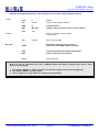
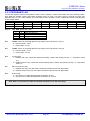
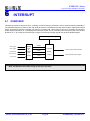
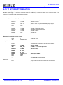
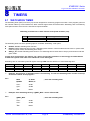
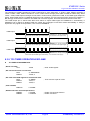
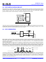
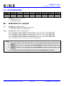
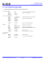
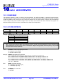
SN8P2318 Series
C-type LCD, RFC 8-Bit Micro-Controller
6.6 EXTERNAL INTERRUPT OPERATION (INT0)
INT0 is external interrupt trigger source and builds in edge trigger configuration function. When the external edge
trigger occurs, the external interrupt request flag will be set to “1” no matter the external interrupt control bit enabled or
disable. When external interrupt control bit is enabled and external interrupt edge trigger is occurring, the program
counter will jump to the interrupt vector (ORG 8) and execute interrupt service routine.
The external interrupt builds in wake-up latch function. That means when the system is triggered wake-up from power
down mode, the wake-up source is external interrupt source (P0.0), and the trigger edge direction matches interrupt
edge configuration, the trigger edge will be latched, and the system executes interrupt service routine fist after
wake-up.
0BFH
PEDGE
Read/Write
After reset
Bit[4:3]
Bit 7
-
Bit 6
-
Bit 5
-
Bit 4
P00G1
R/W
0
Bit 3
P00G0
R/W
0
Bit 2
-
Bit 1
-
Bit 0
-
P00G[1:0]: INT0 edge trigger select bits.
00 = reserved,
01 = rising edge,
10 = falling edge,
11 = rising/falling bi-direction.
Example: Setup INT0 interrupt request and bi-direction edge trigger.
MOV
A, #98H
B0MOV
PEDGE, A
; Set INT0 interrupt trigger as bi-direction edge.
B0BSET
B0BCLR
B0BSET
FP00IEN
FP00IRQ
FGIE
Example: INT0 interrupt service routine.
ORG
8
JMP
INT_SERVICE
INT_SERVICE:
…
; Enable INT0 interrupt service
; Clear INT0 interrupt request flag
; Enable GIE
; Interrupt vector
; Push routine to save ACC and PFLAG to buffers.
B0BTS1
JMP
FP00IRQ
EXIT_INT
; Check P00IRQ
; P00IRQ = 0, exit interrupt vector
B0BCLR
…
FP00IRQ
; Reset P00IRQ
; INT0 interrupt service routine
EXIT_INT:
…
RETI
SONiX TECHNOLOGY CO., LTD
; Pop routine to load ACC and PFLAG from buffers.
; Exit interrupt vector
Page 65
Preliminary Version 0.1