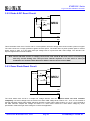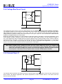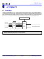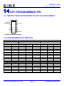
1
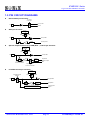
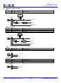
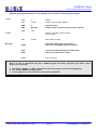
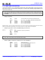
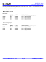
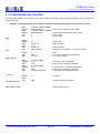
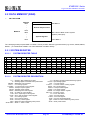
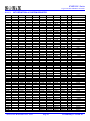
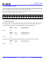
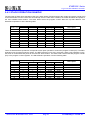
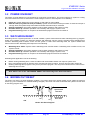
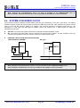
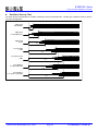
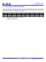
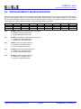
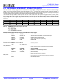
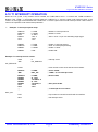
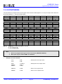
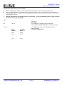
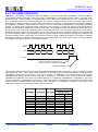
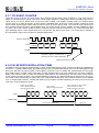
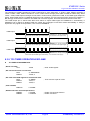
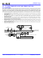
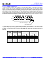
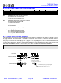
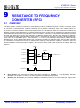
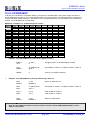
SN8P2318 Series C-type LCD, RFC 8-Bit Micro-Controller 9.4 RFCM REGISTER 0A6H RFCM Read/Write After reset Bit 7 RFCENB R/W 0 Bit 6 - Bit 5 0 W 0 Bit 4 1 W 0 Bit 3 RFCOUT R/W 0 Bit 2 RFCH2 R/W 0 Bit 1 RFCH1 R/W 0 Bit 7 RFCENB: RFC function control bit. 0 = Disable RFC function. 1 = Enable RFC function. Bit 5 Bit 4 RFCM.5 must be set as “0” by program. RFCM.4 must be set as “1” by program. Bit 3 RFCOUT: RFC output control bit. 0 = Disable RFC output, P1.6 is general purpose I/O. 1 = Enable RFC output, P1.6 is RFCOUT pin. Bit[2:1] RFCH[2:1]: RFC input channels select bit. 000 = Select RFC0 channel. Disable P1.0 GPIO function. P1.1, P1.2, P1.3, P1.4 are GPIO mode. 001 = Select RFC1 channel. Disable P1.1 GPIO function. P1.0, P1.2, P1.3, P1.4 are GPIO mode. 010 = Select RFC2 channel. Disable P1.2 GPIO function. P1.0, P1.1, P1.3, P1.4 are GPIO mode. 011 = Select RFC3 channel. Disable P1.3 GPIO function. P1.0, P1.1, P1.2, P1.4 are GPIO mode. 100 = Select RFC4 channel. Disable P1.4 GPIO function. P1.0, P1.1, P1.2, P1.3 are GPIO mode. 101~111 = Reserved. P1.0, P1.1, P1.2, P1.3, P1.4 are GPIO mode. Bit 0 RFCH0 R/W 0 Note: 1. Before RFC enable, P1.0~P1.4 must be set as input mode without pull-up resistor first by program. 2. RFCM.4 must be set as “1” by program through MOV/B0MOV instruction because the bit is write only type. 3. RFCM.5 must be set as “0” by program through MOV/B0MOV instruction because the bit is write only type. 4. We strongly recommend controlling RFCM register through MOV/B0MOV instructions. SONiX TECHNOLOGY CO., LTD Page 100 Preliminary Version 0.1