1
इंटरनेट
मानक
Disclosure to Promote the Right To Information
Whereas the Parliament of India has set out to provide a practical regime of right to
information for citizens to secure access to information under the control of public authorities,
in order to promote transparency and accountability in the working of every public authority,
and whereas the attached publication of the Bureau of Indian Standards is of particular interest
to the public, particularly disadvantaged communities and those engaged in the pursuit of
education and knowledge, the attached public safety standard is made available to promote the
timely dissemination of this information in an accurate manner to the public.
“जान1 का अ+धकार, जी1 का अ+धकार”
“प0रा1 को छोड न' 5 तरफ”
“The Right to Information, The Right to Live”
“Step Out From the Old to the New”
Mazdoor Kisan Shakti Sangathan
Jawaharlal Nehru
IS 15683 (2006): Portable fire extinguishers - Performance
and construction - [CED 22: Fire Fighting]
“!ान $ एक न' भारत का +नम-ण”
Satyanarayan Gangaram Pitroda
“Invent a New India Using Knowledge”
“!ान एक ऐसा खजाना > जो कभी च0राया नहB जा सकता ह”
है”
ह
Bhartṛhari—Nītiśatakam
“Knowledge is such a treasure which cannot be stolen”
IS 15683 : 2006
an 21 I1FfCl?
~f7
\'..:.J CslIQ£f
\3lfT;r ~Tf1lCl)
-
~
\3fu: ~ -
~
Indian Standard
PORTABL.E FIRE EXTIN'GUISHERS - PERFORMANCE
AND CONSTRUCTION - SPECIFICATION
I(~S
c
13.220.10
BIS 2006
BUREAU OF INDIAN STANDARDS
MANAK BHAVAN, 9 BAHADUR S.~A.1 ZAFAR MARG
NEW DELHI 110002
August 2006
Price Group 10
AMENDMENT NO.1 DECEMBER 2008
TO
IS 15683 : 2006 PORTABLE FIRE EXTINGUISHERS PERFORMANCE AN)) CONSTRUCTION SPECIFICATION
(Foreword) - Add the following after the second para:
'The following standards shall be withdrawn with the implementation of this
standard:
1) IS 940 : 2003 Specification for portable fire extinguishers, water type
(gas cartridge)"ifourth revision)
2) IS 2171 : 1999 Specification for portable fire extinguishers, dry powder
(cartridge type) (fourth revision)
3) IS 6234 : 2003 Specification for portable fire extinguishers, water type
(stored pressure) (second revision)
4) IS 10204 : 2001 Specification for portable fire extinguisher, mechanical
foam type
5) IS 13849 : 1993 Specification for portable fire extinguisher, dry powder
type (stored pressure)
6) IS 15397 : 2003 Specification for portable fire extinguisher, mechanical
foam type (stored pressure)
Clause 3.1(a) of IS 2878 : 2004 'Specification for fife extinguisher, carbon
dioxide type (portable and trolley mounted) (third revision)' shall also be
deleted simultaneously with the implementation of this standard.
(Page 1, clause 3.6, line 3) - Substitute '55 ± S·C' for '65 ± S·C'.
(Page 2, clause 4, Note 3) - Delete '(Halotron,NAF,PV, HFC..36), .
(Page 3, clause 6.1, line 3) (30 bar)'.
Substitute '3.5 MPa (35 bar)' for '3 MPa
[Page 3, clause 7.3.I(c)] - Substitute the following for the existing:
Amend No. t to IS 15683 : 2006
'c) not retain more than 10 percent (for dry chemical powder type) and S
percent (for other extinguishers) of initial charge within the extinguisher,
following completedischarge.'
(Page 6, Table'3, 81 No.3, col 3) - Substitute '55 :t: s' for '60:1:2'.
(Page 7, Table 4) - Add the following Note at the end:
'NOTE - The fire ratina shall be declared by the manufacturer basedon the tat report of a
recognized laboratory. '
(Page to, Table S) existing note as Note I:
Add the following as Note 2 and renumber the
'NOTE 2 - The fire ratingshall.bedeclared by the manufacturer. '
(Page 12, clause 8.3.3, line 18) - Substitute 'at the decision of the
operator' for 'but not the back ofthe crib, at will'.
(Page 12, clause 8.3.3, last sentence) -
Delete 'to ensure a continuous
jet'.
[Page 13, Table 9,footnote marlced3~ (Page 16, clause 9.1) -
Delete last sentence.
(Page 16, clause 9.2.1.8.1, line 2) (Page 20,
Delete.
Substitute '55 % S·C' for '5S ·C'.
clause 9.9.1) - Substitute the following for the existing:
"Hose Assembly - Extinguishers having a mass .of extinguishina medium
greater than 3 kg, or a volume of extinguishing medium greater than 3 I shall be
providedwith a discharge hose.
The length of the flexible section of the hose assembly shall be 400 mm or
greater.'
(Page 25, clause 10.2.2.2, Warning):
a)
Delete'Donotuse---perextinauisher.'
2
Ameod No.1 to IS 15683 : 2006
b) Delete the entire 'NOTE'.
(Page 2S. clause 10.2.3.1, last sentence) the existing:
Substitute the following for
'A written description for each use code symbol may be included as part of the
code. The description should be readable.'
(CED22)
RcpI'OII'Iphy Unit,81S.New Delhi. India
3
A" . ....II\1t:...T '\'0. 2 NOVE \lIIER 2UU'J
TO
1 ~6S3 ;
IS
~
2006 PORlAII...: FIR E EXTI"i G l.:ISIU:RS I'~ ,H HI H\I A'\' CE ..\.'\' D C O r-;ST R l 'CTIO N _
Sr EC IFl CATl n ,
/'''P
~ . d_~
-.c..1. I,,,,, ] f -
f"I~".. ,"t . Il <t (,,,, ...
T. bk
~
Delel¢ '., 11<(,,,,:11 i ~ I ~ h ~ 1II' ... d odd 'M
"'me.'
" .. ".a' bf f U'-':.""'Ot '\I od ' . .. l ,_
Obl.i. ""i .i'n..
Clo.. B R.c"0ll:
F.• l lnt .. " .......
(0
_. ,. .
-,.,
L2 l
"
~..... ....
•
t c,
, , , -1
«
: . /-
,,.
0'.''''
f r - .. w_
'!.
,.":
~
, • I, •
t· d ... ~ ...~ . ~ , -
.
.
q ~ .
~ ,Il
......u
~N
.....-
' '"' 'R .......
'",
•
•
,Lo_ ' .2.S .. ' , 1. 1 _
,"",' I" WId """""""" t!l<' ""'''Oqllml cbusft _
'A
._-
.......-o.oc "..... ~-.._' K......'
..,..,,',..
, ...... .. 1 . .
, ~, ........ .1_
buIJ "(,, " 'ng~'.Jltnc colour 01 ~ pm:.... "I' .... IOke ...,. ..,...1 ...,
f.. " iff........ h r<",( ",-""",.-m.n
r-:
.~
,
,
,
<..
-,- .--•.•
'-
-~
c -.. ~
~-
••
AID. 1td
~ O .l IQ
IS
1 5 ~ !l3 :
1006
"The marks .~ir",d obu~. >1>.011 Ix: ~pphal ", 1t1. ","," I of !he body by hard
".mp,ns «n1gn~iIIg.•
(CWL'!)
,
AMENDMENT NO. 3 FEBRUARY 2010
TO
IS 15683 : 2006 PORTABLE FIRE EXTINGUISHERS ―
PERFORMANCE AND CONSTRUCTION ―
SPECIFICATION
(Page 23, clause 10.1) ― Delete the following last sentence:
‘The paint shall conform to IS 2932.’
(CED 22)
Reprography Unit, BIS, New Delhi, India
Fire Fighting Sectional Committee, CED 22
FOREWORD
This Indian Standard was adopted by the Bureau of Indian Standards, after the draft finalized by the Fire Fighting
Sectional Committee had been approved by the Civil Engineering Division Council.
Thisstandardhas been prepared with a view to guide the industriesfor the manufacture and users in manufacturingand
procuringvarious types ofportable extinguishers, capable of giving satisfactory performance. The details with regard
to maintenance are given/inIS 21,90: 1992 'Code of practice for selection, installationand maintenanceof first-aidfire
extinguishers (under revision)'.
Forthe purposeof deciding whether a particular requirementof this standard is complied with, the final valueobserved
or calculated, expressing the result ofa test or analysis, shall be rounded off in accordance with IS 2: 1960 'Rules for
roundingoff numericalvalues (revised)'. The number ofsignificant places retained in the rounded offvalue should be
the same as that of specified value in this standard.
IS 15683 : 2006
Indian Standard
PORTABLE FIRE EXTINGUISHERS - PERFORMANCE
AND CONSTRUCTION - SPECIFICATION
1 SCOPE
This standard lays down requirements for performance,
; reliability and safety of portable fire extinguishers of all
types specified in this standard.
1 REFERENCES
The standards listedat AnnexAcontain provisions which
through reference in this text, constituteprovisions of this
standard. Atthe timeofpublication,the editionsindicated
were valid. All standards are subject to revision and
parties to agreements based on this standard are
encouraged to investigate" the possibility of applying the
most recent editions of the standards indicated at
AnnexA.
3 TERMINOLOGY
For the purposes of this standard, definitions given in
IS 7673 and the following definitions shall apply:
3.1 Classifiration of Fires -
person(s). A fully chargedportablefireextinguishers shall
not be more than 17 kg. The extinguishing medium is
discharged and directed into fire by storage pressure or
release of pressurized charged storage in a cartridge.
3.3 Extinauishing Medium - Substance contained in
the extinguisher that causes fire extinguishment such as
water, foam, powder, gaseous agent(C02, halocarbon) etc.
3.4 Charge of Extinguisher - Mass (kg) or volume
(Iitres) of the extinguishing medium contained in the
extinguisher expressed in volume for water based
extinguishers and in kg for gaseous and powder
extingu ishers.
3.5 Service Pressure (P,> - Equilibrium pressure
developed in a normally charged and pressurized
extinguisher conditioned at 27 ± 5°Cforat least 18h stored
pressure or pressure generated during actuation of gas
cartridge.
Fires may be classified as
follows:
Fires involving solid combustible
materials of organic nature such as wood, paper, rubber,
plastics etc, where the cooling effect of water is essential.
3.1.1 Class A -
3.6 Maxinlum Service Pressure (P.) -
Equilibrium
pressure developedin a normally chargedand pressurized
extinguisher which is conditioned at 65 ± SoC for at least
18 h.
3.1.2 Class B -
3.7 Complete Discharge or Extinguishing Medium
in Percentage and Time - Point in the discharge of an
3.1.3 Class C - Fires involving flammable gases under
extinguisher when the internal pressure hasequalized with
the external pressure, with the valve control being kept
fully open that is the point at which pressure on dial
becomes zero.
Fires involving flammable liquids or
liquefiable solids or the like where a blanketing effect is
essential.
pressure including liquefied gases, where it is necessary
to inhibit the burning gas at fast rate with an inert gas,
powderor vaporizing liquid for extinguishment.
3.1.4 Class D - Firesinvolving combustible metals such
as magnesium, aluminium, zinc, sodium, potassium, etc,
whenthe burningmetalsare reactive to water containing
agents and in certain cases carbon dioxide, halogenated
hydrocarbons andordinary dry powders. Thesefirerequire
special mediaand techniques to extinguish.
3.2 Portable Extinguisher - Portablefireextinguishers
are not expected to deal with large fires. Nevertheless.
these are very valuable in the early stages of fire. The
most important features of these extinguishers are there
immediately availability and can be used by one/two
Time measured from
the commencement of discharge of the extinguishing
medium at the nozzle to the point of the discharge stream
with the control valve fully open when 85 percent of
extinguishant is discharged incase powderand 95 percent
in case of water and gas based extinguishers.
3.8 Effective Discharge Time -
3.9 Rechargeable Extinguisher designedto be recharged after use.
Extinguisher
3.10 Disposable Extinguisher (Non-rechargeable
Extinguisher) - Extinguisher designed not to be
recharged, but intendedto be discarded after use.
3.11 Fill Density -
Mass in kg of extinguishing medium
IS 15683 : 2006
5.1.3 Powders
Powder for Class Be should comply with IS 4308, for
ClassABC IS 14609 and powdersfor useon ClassD fires
shall complywith IS 4861.
.
per litre of container volume for use,complete with valve
and internal fittings.
3.11 Propellant - Non-flammable compressed gas used
to expel theextinguishing medium that is CO2 and N 2 etc.
5.1.4 Foam Concentrates
3.13 Clean Agent - Electrically non-conductive
gaseous or vaporizing liquid fire extinguishant that does
not leave a residue uponevaporation and are not toxic to
level of concentration at which it extinguishes the fire.
Foam concentrates usedinextinguishers shall comply with
IS 4989 or ISO 7203.
NOTE - There is no Indian Standard covering non-foaming
additives sometimes addedto waterto produce anti-freezc, wetting
or otherspecial characteristics. However, such extinguishers are
included in the category of water-base extinguishers. the wateranti-freeze solution be tested for its freezing point and thawing.
Calcium chloride solution shall not be usedforstainless steel fire
extinguishers.
3.14 Lowest Observed Advene Effect Level (LOAEL)
- The lowest concentration of clean agent at which an
adverse toxicological or physiological effect has been
observed.
3.IS No Observed Advene Effect Level (NOAEL)The highest concentration of a clean agent at which no
adverse toxicological or physiological effect has been
observed.
5.2 Propellants
The propellants forstoredpressure and cartridge-operated
extinguishers shall be air, carbon dioxide, nitrogen or
mixtures of these gases having a maximum dew-point
of-55°C.
4 CLASSIFICATION OF EXTINGUISHERS
Extinguishers shall be classified by the type of
extinguishing medium which they contain.At present, the
main types of extinguishers are:
Propellant forstored-pressure water-based extinguishers
neednot meetthe abovedew-point requirement.
NOTE -
5.3 Filling Requirements (Type Test)
a) wateror/andfoam based,
b) powder,
S.3.1 Fill Density
c) carbon dioxide, and
Themaximum filldensity forcarbondioxide extinguishers
shallnot exceed 0.75 kg/I. The fill density forcleanagent
fire extinguishers shall not exceedthe values givenin the
relevant standards.
d) cleanagents.
NOTES
I These types of extinguishers may be further sub-divided. for
example water-based extinguishers maycontainpurewateror water
with additives such IS wetting agents,viscosity-increasing agents,
flame-retardant, or foamina apnts, etc.
5.3.2 Filling Tolerance
The actualchargeof an extinguisher shall be the nominal
.charge within the following limits:
2 Powders maybe ofthc 'Be' or 'ABC' types, or may bespecially
prepared for Class D(metals) fires.
a) water-foam based extinguisher : .~ percent by
volume;
3 Clean alents which are halon substitutes that is HFC, HCFC
blends etc (Halotron, NAF PV, HFC-36), Fluoro ketone. The
manufacture and useof halocarbon including halons are regulated
by the Montreal Protocol and/or by national regulations.
b) powderextinguishers
S I kg nominal charge ± 5 percentby mass;
> 1 kg but < 3 kg nominal charge ± 3 percentby
S EXTINGUISHING MEDIA, PROPELLANTS
AND FILLING REQUIREMENTS
mass;
~ 3 kg nominal charge ± 2 percentby mass;
c) clean-agent extinguishers
.~ percent by mass; and
d) carbon dioxide extinguishers
.~ percent by mass.
S.I Extlnlulshinl Media
S.I.I Carbon Dioxide
Carbon dioxide used in extinguishers shall comply with
IS 15222.
S.3.3 Capacities
The following are the recommended capacities for fire
extinguishen:
a) water-foam based (litres): 2, 3, 6, 9;
5.1.2 CleanAge"ts
Clean agents used in extinguishers shall comply withthe
IS I S493 or standard of clean agent supplied by
manufacturer. (To be confirmed for test methods.)
b) powder (kg): 1, 2, 3, 4, 6, 9;
2
IS t 5683 : 2006
c) CO2 (kg): 2. 3, 4.5 and 5; and
d) clean agent (kg): I, 2, 4, 6.
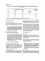
Table I Minimum Effective Discharge Time of
Class B Rated Extinguishers
(Clause 7.2.2)
6 PRESSURE REQUIREMENTS FOR LOW
PRESSURE EXTINGUISHERS
Classification
Minimum Discharge
Time
s
(2)
Throw
m
6.1 Test Pressure (P.>
(I)
The testpressure (P.) for low-pressure extinguishers shall
be 1.43 x Pms but in no case less than 2 MPa (20 bar).
88
8
I
138
8
I
21B
8
2
348
8
2
Forgaseous extinguisher, it shouldnot be lessthan 3 MPa
(30 bar).
6.2 Minimum Burst Pressure (P J
The minimum burst pressure (P b) for low-pressure
extinguishers is2.7 x Pnil but in no case lessthan5.5 MPa
(3)
7.2.3.2 Test method
Carryout the test indoors having suitable lighting to give
thebestpossible visibility of theextinguisher media during
discharge. Use a blackbackground marked to indicate the
horizontal distance. Condition the extinguisher for no less
than 18h at atemperature of27± 5°Candplace it in normal
operating position with the discharge nozzle held
horizontally I m above the floor. Fully discharge the
extinguisher with the control valve fully open within
5 min of conditioning. Recordthe bulkrange (through) of
the extinguisher as the range at the time corresponding to
SO percent of the effective discharge time that is if
discharge time is ISs. The range should be minimum up
.
to 7.5 s.
(55 bar).
7 GENERAL OPERATING PERFORMANCE
REQUIREMENTS
7.1 Operating Temperatures
Extinguishers shallbecapableof operating reliably within
one of the following temperature ranges of temperature:
+ 5 °C to + 5S °C
o °C to + SS °C
- 10°C to + 55 °C
NOTE - Where the range of effective discharge is difficult to
determine visually, supplementary means, suchascollection boxes
for powders and condensing plates for liquefied gases may also
be used.
- 20°C to + 55 °C
- 30°C to + 55 °C
NOTE - The temperature rangeselectedfromthe aboveshall be
marked on the fire extinguisher (see 10.2.I.S).
7.3 Resistance to Temperature Changes (Type Test)
7.3.1 Requirements
7.2 Minimum Effective Discharge Time and Bulk
Range of Discharge
Portable extinguishers shall be able to operate at
temperatures within one of the temperature ranges given
in 7.1 as indicated by the manufacturer and comply with
the following requirements after being subjected to the
conditions given in 7.3.2:
7.2.1 Class A Rated Extinguishers
. The minimum effective discharge time of extinguishers
with IA rating shall be no less than 8 s. Extinguishers
with ratings of 2A or higher shall have a minimum
discharge time of 13 s.
a) shall operate as intended;
b) commence discharge within 5 s of the opening of
control valve; and
7.2.2 Class B Rated Extinguishers
The minimum effective discharge time of extinguishers
with a Class B ratingshall be no less than the value given
in Table I.
c) not retain more than 10 percent of initial charge
within the extinguisher following complete
discharge.
7.3.2 Test Method
Subjectfour(two)extinguishers to the temperature cycles
given in Table 2, two extinguishers to each cycle.
7.2.3 Bulk Range/Throw (7Ype Test)
7.2.3.1 Requirements
The minimwn bulk rangeof extinguishers witha ClassA
rating shall be no less than 2 m when determined in
accordance with 7.2.3.2.
Operatethe extinguisher within 5 minof its removal from
the conditioning chamber.
3
IS 15683 : 2006
Table 2 Temperature Cycles
(Clause 7.3.2)
Duration
h
Cycle I
Cycle 2
(1)
(2)
(3)
I)
*I
Storeat minimum" statedtemperature (.~ °C)
Storeat (55 :I: 5)OC
24:1: J
Storeat (27 2: Sloe
Storeat (27 :t Sloe
24:t I
Storeat (S5 :t: Sloe
Storeat mini) stated temperature (.~ °e)
24
See 7.1 temprature range marked on the extinguisher.
Thestorage temperatures referto the ambienttemperature within the conditioning chamber. A liquidbath shall not be used.
allowing the discharge of the extinguishing medium to be
interrupted at any time.
The extinguisher is to be held in its normal working
position andshallremain immobile for the duration of the
test.
The extinguisher shall be adequately resistant to leakage
and the second pressure (or weight of contents as
appropriate) shall be no less than 75 percent of the first,
afterinterruption of thedischarge as determined in 7.4.2.2.
NOTE - Forcartridge operated extinguishers the cartridge shall
bepierced andthe pressure allowed to buildfor6 5 before opening
the control valve.
7.4 Retention orCharge
7.4.2.2 Test method
7.4.1 Routine Checks
Discharge a fully charged extinguisher for a period equal
to half the time for total discharge and the control valve
shall then be closed. Measure the internal pressure (or
weight of contents as appropriate) and after a further
5 minwith the valvehaving remained closed, measure the
pressure (or weight of contents as appropriate) again.
7.4.1.1 Extinguishers and gas cartridges shallbe designed
so as to permit their charge to be checked at regular
intervals when they are installed as per IS 2190.
7.4.1.2 The charge of the following shall be measured by
weighing:
a) All types of gas cartridges for extinguishers;
b) Carbon dioxide extinguishers; and
c) Stored-pressure extinguishers of various types
including someclean agents in which a mass loss
of I percent of total mass is accompanied by a
pressure loss of not more than 10 percent of the
service pressure at 27 ± SoC.
7.4.3 Long- Term Leakage Test (TYpe Test)
7.4.3.1 Requirements for stored-pressure extinguishers
Stored-pressure extinguishers covered in 7.4.1.3 shall not
leak at a rate exceeding 5 percent per annum of service
pressure.
7.4.3.2 Requirements for gas cartridges and extinguishers
checked by mass
7.4.1.3 The charge of stored-pressure extinguishers of
types not covered in 7.4.1.2 (b) and (c) shall be checked
by direct measurement of internal pressure at 27 ± SoC.
For this purpose, the extinguisher shall be fitted with a
built-in pressure-indicating device, which can be checked
for satisfactory operation.
Long-term leakage requirements are as follows:
a) Stored-pressure extinguishers without a pressure
gauge shall not leak at a rate exceeding S percent
of its contents per annum or 50 g per annum,
whichever is less [see 7.4.1.2 (cj];
b) Gas cartridges shall not leak at a rate exceeding
5 percent of its contents per annum or 7 g per
annum, whichever is less; and
c) Carbon dioxide extinguishers shall not leakat a rate
exceeding S percentof its.contents per annum.
A connection towhich an independent pressure-measuring
appliance can be attached may be used as the means for
checking the built-in pressure-indicating device; in this
case, a connection of this type shall be equipped with a
pressure-retaining cap.
7.4.3.3 Test method
7.4.2 Retention ofCharge Following Partial Discharge
Check six samples for leakage after 30, 90 and 120days.
Any loss in pressure or contents at constant ambient
temperature is anindication ofa leak. Measure the leakage
7.4.2.1 Requirements
Fire extinguishers shall be fitted with a control valve
4
IS 15683 : 2006
interms ofweightor pressure loss, whichever isapplicable.
7.5.2.1 Test principle
An extinguisher shall be capableof withstanding exposure
to the conditions of a vibration test without development
of physical weakness. which would impair its normal
operation.
7.5 Mechanical Resistance (Type Test)
7.5.1 Resistance to Impact
This test is intended to prove the resistance of the
extinguisher. and particularly that of the headand fittings,
to damage from falling objects or from impact with fixed
surfaces.
7.5.2.2 Extinguisher mounting requirements
Extinguishers supplied with a wall hook or bracket not
intended for use in vehicles shall be subjected to the test
specified in 7.5.2.5.2.
7.5.1.1 Requirements
Theextinguisher shallnot releasepressure in a potentially
dangerous manner when testedinaccordance with 7.5.1.2.
Extinguishers supplied with a bracket for use in vehicles
shall be subjected to the test specified in 7.5.2.5.3.
7.5.1.2 Test method
Extinguishers supplied with a bracket suitable for both
general and vehicle use shall be subjected to the test
specified in 7.5.2.5.3.
Condition anextinguisher, correctly charged andequipped
with all the fittings which are subject to internal pressure
in normal operation, for 18 h to the minimum' working
temperature (see 7.J) with a tolerance of ± 5°C, and
maintain it at this temperature during the impact test
described below.
7.5.2.3 Test criteria
The test criteria are as follows:
a) Following exposure to the vibration test the
extinguisher shall comply with the discharge
requirements specified in 7.2; and
If the extinguisher is of the gas cartridge type, fit the
charged cartridge and activate the extinguisher with the
control valve shut, so as to keep the extinguisher under
pressure.
b) Physical failure ofcomponents which would require
repair or replacement of the extinguisher and/or
components before it can be returned to normal
serviceshall be cause for rejection.
Conduct the impact test as follows:
7.5.2.4 Mounting ofthe test specimen
Mount a steelcylindrical hammer, of75 mmdiameter and
total mass of 4.0 kg with flat faces, vertically in loose
guides so that it can drop freely through a height h
(minimum height 300 mm) given by:
Mount a fully chargedextinguisher in an upright position.
Mount extinguishers intended for use in vehicles in their
intended bracket. Extinguishers not intended for use in
vehicles may be tested without a bracket.
m
h = - - ' and h ~ 0.3
20
7.5.2.5 Test orientation
where
h = height, expressed in m: and
m = total mass of extinguisher, expressed in kg.
7.5.2.5.1 Axes a/orientation
Subject the extinguisher to the vibration test specified
in 7.5.2.5.2 or 7.5.2.5.3 in each of the three rectilinear
axes in thefollowing order: horizontal. lateral, andvertical.
The extinguisher shall be placed on a rigid flat surface.
protecting pressure gauge, in each of the following two
positions in tum:
a) inthenormal upright position, withthe longitudinal
axisof the hammer coincident withthe longitudinal
axis of the valve; and
b) lying on its side so that the valverests on a rigidly
fixed steel block.
7.5.2.5.2 General extinguishers
Thevibration appliedshallhave thefollowing parameters:
Frequency : 40 Hz
Amplitude: 0.25 ± 0.03 mm
Duration : 2 h (in each orientation specified in
7.5.2.5.1)
In each of the above positions, submit the valve of the
extinguisher to an impact by allowing the steelhammer to
fall vertically onto'itfrom the height h. The pointof impact
is to be examined.
7.5.2.5.3 Vehicle extinguishers
Subject the vehicleextinguishers to the following tests:
a) Subject the extinguisher to the variable frequency
and amplitude specified below in each orientation
specified in 7.5.2.5.1.
7.S.2 Resistance to Vibrations (7ype Test)
5
IS 15683 : 2006
Frequency, Hz
Amplitude, nun
10 to 19
0.75 ± 0.08
O.SO:l: 0.05
0.25:l: 0.03
20 to 39
40 to 60
Table 3 Temperature Cycle
(Clause 7.6.2)
Vibrate theextinguisher for S min at each frequency
and increase the frequency at discrete intervals of
2 Hz, and
Stale
Dur.doD
h
Temperature, °C
(1)
(2)
(3)
I
27:t: ,
2
3
4
b) Vibrate the extinguisher for 2 h at the frequency
which produced the maximum resonance as
determined in (a) above or if no resonance is
observedsubjected to the test specifiedin 7.S.2.S.2.
~
27
27± S
~
27
27:1: S
60± 2
27 ± S
The temperature refers to the ambient temperature of the conditioning
chamber. A liquid bath shall not be used. The duration of anyone
complete cycleshallnot exceed 120h.
I)
Completethe tests specified in (a) and (b) above in one
plane before making tests in the next plane.
The lowest temperature marked on theextinguisher ± 2°C(.fee 7.1).
protectivecoating local to the planeof section.There shall
be no v.isible signs of corrosion of the metal nor
detachment, cracking or bubbling of any protective
coating. There shall be no visible change in the colour of
the extinguishingmedia other than that resultingfrom the
thermal cycling in case of water based media only.
7.6 Resistance to Corrosion (Type Test)
7.6.1 External Corrosion Test
Subject complete and fully charged extinguishers,
including their mounting bracket and wall hook, to a salt
spray test as defmed in IS 6910 for a period of 240 h.
Following a drying period of at least 24 h at room
temperature, carefully wash the extinguisher to remove
any salt deposits. Test two samples that is either two of
the same size or one sample each of two different sizes
from the same family.
NOTE - Allowance should be madefora change of colour that
occurs naturally dueto thetemperature changes. It isrecommended
that twosamples of the agentbe stored in closed glasscontainers
and subjected to the samecycles as the extinguishers in orderto
establish a reference sample.
7.7 Tapping Test (Type Test)
At the conclusion of the test the following requirements
shall be satisfied:
7.7.1 Requirements
Portable extinguishers shall comply with the following
requirements after being subjected to the conditioning
specified in 7.7.3 :
a) The mechanical operationofall workingparts shall
be unimpaired;
b) The minimum effectivedischarge time and method
of operation shall comply with requirements
specified;
a) Shall operate satisfactorily;
b) Commence discharge within 5 s of the opening of
the control valve; and
c) The pressure gauge, if one is fitted, shall remain
functional and watertight; and
c) Not retain more than the following percentage of
initial charge within the extinguisher following
complete discharge:
d) There shall be no corrosion of the metal of the
extinguisher body; discolouration/superficial
corrosion of non-ferrous metals is acceptable, but
galvaniccorrosion between dissimilar metals shall
not be permitted.
1) powder: 15 percent
2) all other media: 10 percent.
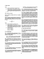
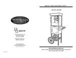
7.7.2 Test Apparatus
7.6.2 Internal Corrosion Test for Extinguishers Using
Water-Based Media (Type Test) and Gaseous
Extinguishers
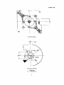
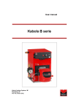
7.7.2.1 Compactionmachine,designed to acceptonlyone
extinguisher at a time which shall be raised by rod and
guided by castors.
Subjecttwoextinguishers, charged in accordance withthe
manufacturer's filling instructions, eight times to the
temperature cycle defined in Table 3.
On completion of the eight temperature cycles, cut each
The plate supporting the extinguisher shall be of steel
300:1: S. rmn.square and 60 ± I mm thick. Figure 1 is an
example of an acceptable test apparatus.
body into two sections in a manner sufficient to pennit
internal examination. Disregard detachment of any
Observe the following points:
6
IS 15683 : 1006
a) Ensure that the rod is adjustableas to adjust to the
extinguisher base;
openingthe control valve.
b) Ensure that the rod can move freely in the guide
cators; and
8 PERFORMANCE REQUIREMENTS FOR
TEST FIRES
·
c) Extinguisher shallalsobeguidedwithout constraint.
8.1 Rating Suitability for tbe Various Classes or Fire
7.7.3 Test Method
8.1.1 Class A
An extinguisher in a normally chargedcondition shall be
heldin the vertical position and droppedvertical SOO times
froma heightof I 5 mmat a frequency of 1 Hz onto a rigid
horizontal steel plate.
The rating of extinguishers recommended as suitablefor
Class A fires shall be determined using the method
described in 8.3. The ratingshall be basedon the amount
of extinguishing medium used to extinguish the fire of
maximum sizeundertheconditions of thetest. Thisamount
shall jJe no lessthantheappropriate minimum valuegiven
in Table 4.
The extinguisher is to be removed fromthe test apparatus
with a minimum amount of agitation, held in its normal
working position, and operated.
8.1.2 Class B
NOTE - Forcartridge extinguishers, the Cll'tridge shall bepierced
and the pressure allowed to build for 6 s before opening of the
control valve.
The rating of extinguishers recommended as suitable for
Class B fires shall be determined using the method give
in 8.4. The rating shall be based on the amount of
extinguishing medium used to extinguish the fire of
maximum sizeundertheconditions of thetest. Thisamount
shall be no lessthanthe appropriate minimum valuegiven
in Table S.
7.8 Intermittent Dlscharee Test
7.8.1 An extinguisher conditioned at its minimum
operating temperature ± 2°Cand at SS ± S °Cshalloperate
in such a manner that no more than 1 s elapses from the
time the control valve is opened until the extinguishing
media starts to discharge. Additionally, at the end of
discharge, the extinguisher shall not retain more than the
following percentages of its original charge:
a) powder: IS percent;and
b) all others: 10 percent.
8.1.3 Class C
There are no tests requirements for the performance of
extinguishers against Class C fires included in this
standard, suitability for useagainst ClassC may be claimed
for Class B or Class AB powderextinguishers only.
7.8.2 Condition a correctlychargedextinguisher at each
of the specified temperatures for a min of 18 h. Operate
the extinguisher intennittently by openingand closingthe .
valvein cyclesof2 s 'open' and 2 s 'closed' untiltheend
of discharge is reached.
8.1.4 Class D
Extinguishers recommended as suitablefor Class D fires
shall extinguish theappropriate testfire orfires when tested
as described in 8.5.
NOTE - Extinguishers suitable forClass 0 fires are usually not
suitable for use on firesof other classes, Specialized mediaand
applicators arc typically used.
7.8.3 For cartridge-operated extinguishers, pierce the
cartridge and allow the pressure to build for 6 s before
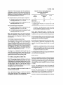
Table 4 Amount 01 Extinguishing Medium Used to Obtain a Minimum Class A Rating of Extinguishen
(Clause 8.1.1)
Eltlnlulshlna ~~dlum Content (Charae)
Minimum
Class A Ratina
WaterlFoam
Water withAdditives
Clean'Agent
k&
(1)
(2)
(3)
Powder
1~2
I~
kg
6
(4)
Is; 6
lA
2 </~4
6 < Is 10
6< Is 8
2A
4<1~6
1>10
I> 8
3A
6</~9
4A
/>9
6A
7
IS 15683 : 2006
11
1
2
~---19
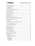
1A GeNERAl
DIAGRAM
Key
Castor
15. Adjusting block
Cam
16. Support axes
1.
Castorsupport axis
2.
Castors
8.
9.
3.
CI + C, M12 - 190 screw
10. Inductive pick-up
4.
Push-nut extinguisher
11. Rotation guidance
5.
H, M16-90 screw
12. Axes
6.
Plates
13. Castor nut
7.
Piston
14. Support plate
Flo. 1
TAPPINO MACHINE -
8
17. Plate support axis
18. Flender-Himmel gearedmotor
19. Systemsupport plate
Continued
IS 1S683 : 2006
+
_.m-.I
"OJ
+
..
i
1B Viewfrom Above
T
5044'
~.
20
II
I
I
Alldimensions in millimetrcs.
1C SideView
Fla. 1 TAPPINO MACHINE
9
IS 15683 : 2006
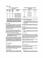
Table S Amount or Extinguishing Medium Vsed to Obtain Minimum Class B Rating of Extingulshen
(Clause 8.1.2)
Eltlnguishlnl Me~lum Content (Cba"'~J
,
Minimum
Cllss B Rating
CleanAgent
kg
Carbon Dioxide
kg
k&
Foam or Water
with Additives
(I)
(2)
(3)
I
(4)
(5)
l!a 2
Is 2
l!a 2
S
88
Powder
i« 2
Is 2
Is 2
S
138
2 < Is 3
2 < Is S
2< Is4
9
218
3 < Is 4
1>5
4 < Is6
9
34B
NOTE -
At present the cleanagentapproved internationally forthis purpose are HFe and HCFC.
particular metal or form of metal is established by
extinguishing eitherthe first fire of the set,or if this is not
extinguished, extinguishing the second andthirdtestfires.
8.2 Test Fires - General
8.2.1 Operator s Clothing
To carry out these tests the operator shall wear suitable
protective clothing including shoes, helmet, visor, gloves
etc.
A set comprises fires consecutively carried out and the
result of any particulartest fire is not to be disregarded.
Eachset is to be completed before anotheris started. For
ClassA and ciass B fires, a set is completed eitherwhen
all threetest firesare carriedout or when the firsttwotest
fires are both successful or both unsuccessful. For Class
D fires, a set is complete when the firsttest is successful,
or when the first and second fires are both unsuccessful,
or when all three are carried out.
NOTE - Attention isdrawn to thenecessity fortaking precautions
to safeguard the health and safety of personnel conducting the
testsagainst theriskof fireand inhalation of smoke andanytoxic
products of combustion, and compliance with the national
legislation which mayapplyconcerning the health and safety of
theextinguisher operator and other personnel.
8.2.2 Requirements for Extinguishment
Test fires shall be regarded as extinguished if:
8.3 Class A Test Fire
Class A - All flames are extinguished. There shall
be no flames visible 10 minafter complete discharge
oftheextinguisher. The appearance of non-persistent
flames during the 10minperiodshallbe ignored. Non-'
persistent flames are defined as less than SO mm in
height and less than 1 min duration; if the Class A
crib collapses during the test, it shall be considered
voidand a fresh test carried out.
8.3.1 Location
Conduct the tests in an essentially draught-free room
having adequate volume and ventilation to ensure the
necessary supply of oxygen and reasonable visibility for
the period of the test.
Air inlet openings at or near ground level as given in
Table 6, with a flue area of 4.5 m2 have been found to
provide adequate ventilation.
Class B - All flames are extinguished.
NOTES
I Forexample, ithas been established thata room having a ceiling
height of approximately 3 m and size 7 m x 7 m forclassupto2A
and34 B andofsize ISm x 15m forhigher classes with adjustable
inletopenings near the fourcorners is suitable forthese purposes.
The room should havesmoothly finished concrete floor.
1 This test may be carried out by puttina 3 m high mild steel
sheetenclosing threesidestill infrastructure isdeveloped forindoor
test facilities.
8.2.3 Test Extinguishers and Method ofUse
Use extinguishers filled and charged according to the
manufacturer's instructions. It is permitted, at the
operator's discretion, to operate a gas cartridge
extinguisher so as to allow the operating pressure to
increase in the body prior to discharge.
8.2.4 Test Schedule (lYpe)
The basic schedule of testingis a set of three fires. Class
A or Class B ratingis achieved by extinguishing two out
of three fires of the same size. Class 0 suitability for a
8.3.1 Construction
The test fire consists of a crib made of pieces of wood.
The piecesof wood forming the outsideedgesof the crib
may be stapled or nailed together to provide strength.
10
IS 15683 : 2006
Table 6 Example of Typical Air Inlet Sizes for
Ventilation of Class A Test Fires
(Clause 8.3.1)
Clallineadon
and Ratlnl
specified inTable 7. Stackeachlayerof thepieces of wood
at rightanglesto the layer below. Stack individual pieces
of wood on each layer with even spacingand in the form
of a square with sides equal to the length of the pieceof
wood (see Fig.2).
Air Inlet Opening
Surrace Area
m1
(1)
(2)
Usepiecesof wood of Pinus Sylvestris, or of other wood
which can be shown to be equivalent, of appropriate length
as specified in Table 7 and of square cross-section with
sides of 39 ± I mm, a moisture content of 10 percent to
14 percent by mass (dry basis).
IA
0.10
2A
0.10
3A
O.IS
4A
0.20
NOTES
6A
0.30
1 Wood isconsidered to be equivalent iftheratingachieved using
wood that is not morethan that achieved whenPinus Sylvestris is
used. Cryptomeria Japonica maybe preferred in India.
Construct the crib on two 63 mm x 38 nun angle ironsor
othersimilarandappropriate supports, placedon concrete
blocks or support frame so as the height of the supports
abovethe floor is 400:1: 10 mm.
1 Determine the moisture contentof the pieces of wood using
commercially available instruments which measure electrical
conductivity between needle probespushed intothesticksor other
suitablemethod. Somevariation in reading maybe obtained dueto
structural variation of the timber and the direction of the grain.
Calibrate the instrument by determination of moisture content in
accordance with IS 1708(Part I).
Stackthe pieces of wood in the appropriate arrangement
SUPPORTING
FRAME
FlO.
2
CRIB FIRE
11
IS 15683 : 2006
Table 8 Wood-Crib Ignition Arrangement
(Clause 8.3.3)
Table 7 Wood Crib Construction
(Clause 8.3.2)
aUlA Number or Leftltb or
Ratlnl Pieces or Pieces or
Wood
Wood
Arranlement or
Pleees or Wood
Class A Radna
mm
(I)
(2)
(3)
(4)
lA
72
500
12 layersof 6 piecesof wood
2A
112
16 layersof 7 piecesof wood
3A
144
635
735
4A
180
800
18 layers of 8 piecesof wood
20 layers of 9 piecesof wood
6A
230
9~S
23 layersof 10 piecesof wood
HeptaneCharae J)
mm
/
(I)
(2)
(3)
IA
400 x 400 x 100
1.1
2A
53S )( S3S )( 100
2.0
3A
635 )( 635 x 100
2.8
4A
700 )( 700 )( 100
3.4
6A
825 )( 825 x 100
4.8
I) See
NOTE -Ifneccssary in the future, it is intended that this table be
extended to include larger test tires. These will be constructed on
the same principles as those now listed. Each Class A rating is
designated by a number in a series which is proportional to the
mass ofwoodcontained ina craib. Allcribsarecubicwiththe volume
of the openspaceapproximately equal to the volume of the wood.
I.aldon Pan Size
8.4.3.
are vertical. The base of the trays are set horizontal and
level with the surroundingground.
NOTE- Reinforcement of the base of the larger test fire trays
will be necessary to minimize distortion. In such cases it will be
necessary to ensurethat the underside of the traysarenotexposed
to the atmosphere.
8.3.3 Procedure
Place an ignition pan of appropriate size as specified in
Table 8 on the floor underthe crib. Level the pan as far as
ispossible and add sufficient waterto coverthe base. Pour
the appropriate volume of fuel (as specified in Table 8)
into the pan. Ignite the fuel. Remove the pan once the
liquid has been consumed.
Detailsof Class B test fires are given inTable 9. Eachtest
fire is designated by a number followed by the letter B.
8.4.3 Fuel
Use an aliphatic hydrocarbon havingan initial boiling point
of not lessthan 88°C and a final boilingpointof not more
than lOSoC.
Allow the crib to burn until its mass is reduced to S5 ± 2
percent of its original mass: The mass loss may be
determined directly or by other methods which can be
demonstrated to provide equivalent correlation.
NOTE - Typical fuels meetingthis requirement are n.. heptane
and certainsolventfractions sometimes referred to as commercial
heptane.
8.4.4 Procedure
NOTE- Thiswilltake 6 minto 10min. Eithermonitor the mass
continuously or detenninethe time by a preliminary test or tests,
extinguishing the fire(s) and measuring the mass and core.
diameters makingadjustments as necessary.
8.4.4.1 Add the appropriatevolume of waterand heptane
specified In Table 9. Add additional water to compensate
for distortion of the base so that all points are covered,
subject to a maximum liquid depth of 50 mm and a
minimum heptane depth of 15 mm at any point.
Apply the discharge of the extinguisher to the test fire,
initially to the front. Reduce the distance of attack and
apply the discharge to the top, bottom,front or either side
but not the back of the crib, at will. Maintainall devices
for controlling the flow of the extinguishing media in the
position for maximum discharge to ensure a continuous
jet.
8.4.4.2 For the testing of foam and clean agent
extinguishers use fresh fuel for each test.
8.4.4.3 When testing powder extinguishers it shall be
demonstrable that the rating can be achieved using fresh
fuel.
8.4 Class B Test Fire
8.4.4.4 Ignite thefuel
8.4.1 Location
8.4.4.5 Permit the fuel to burn freely for a minimum of
60 s before operating the extinguisher.
Carryouttest fires upto and including 13B indoors. Carry
outtest fireslargerthan 13B indoorsor outdoorsbut with
thewindspeednot exceeding3 mls. Do not carryout tests
outdoors when rain, snow or hail is falling.
8.4.4.6 Operate the extinguisher and apply the
extinguishing mediumto the test fire.
8.4.2 Construction
Class B test fires utilize a range of welded-sheet-steel
cylindrical trays(dimensions given in Table9). The sides
NOTES
I The extinguisher may be discharled continuously or in
intermittcnt bursts at the discretion of theoperator. The operator
12
IS 15683 : 2006
Table 9 Dimensions of Class B Test Fires
(Clause 8.4.2)
Cla.IOcatlon
Minimum
Dlscharle of
Extlnlulsher
s
Volume
of
Liquid')
Diameter"
Internal
I
mm
Depth"
Dimensions of Test Fire Tray
~----
r-
• •
mm
(1)
(5)
(2)
(3)
570
' 720
21B
8
8
13
21
348
8
34
1170 ± 10
88 3)
138))
(4)
10
10
150 ± 5
150 ± 5
920 ± 10
150* 5
150± 5
±
±
n n _ _ , . _ . " •• _
•• _
••• __
•
___
,
Minimal
Thickness
of Walls
mm
(6)
Approximate
Surface Area
of Fire
2.0
2.0
2.0
0.25
0.41
0.66
2.5
1.07
m2
(7)
NOTE - Each test fire is designated by a number in a series in which eachtermis equal to the sumof the twopreceding terms (thisseries
isequivalent to geometric progression havinga common ratioof about 1.62). Test fires larger thanthosegiven maybe constructed following
the rules of this geometric progression.
"One-thirds waterand two-thirds heptane.
2) Measured at rim.
.')This firesize is for a low-temperature fire testonly.
maymove round the tire in orderto obtainthe bestresults.
Forreasons of safetytheoperator shallnot reach overtheedge
of the tray, and at no time shall the operator ontoor intothe tray.
8.5.2 Metal Chip or Turning Fires
2
8.5.2.1 Construction
The fires consist of a bed of the metal fuel 600 mm x
600 mm squarepositioned centrally on a steel base-plate
1 m x I m squareand 5 mmthick. Usea removable metal
or wood frame to build the bed.
8.5 Class D Test Fire
8.5.1 General
The extinguishment of these test fires is based on the use
of a portable extinguisher havinga nominal charge 10 kg
of media. Extinguishers having a lesser charge shall be
testedusinga proportionally reducedquantity and surface
areaof fuels. Extinguishers witha chargeof lessthan 8 kg
shall not be allowed.
Forignition, usea devicesuch asa gas/oxygen torch which
will ignitethe metalwithin 30 s.
8.5.2.2 Fuel
Carryout four series of tests using:
a) magnesium AI alloy;
WARN/NG - Someextinguishing mediaused for Class D tires
are toxic(forexample, barium chloride BaCI 1) and/ormay' react
with the burning metal to produce materials which are toxic or
otherwise hazardous (forexample, phosphates which reactto form
metal phosphides, which are decomposed by water to produce
phosphine, PH), a spontaneously flammable gas).
t
b) magnesium alloy with cuttingoil;
c) reagent-grade magnesium; and
d) reagent-grade magnesium with cuttingoil.
8.5.2.3 Procedure
Foreach test, prepare the fuel bed inthe removable metal
or wood frame. Level the surface of the fuel usinga rake
or straight-edged board. Remove the frame.
Before carrying out these tests, establish procedures to
protect personnel and to safely dispose of residues from
test tires.
Conduct the tests in an essentially draught-free room
having adequate volume and ventilation to ensure the
necessary visibility for the period of the test.
Apply the igniting torch to the centre of the fuel bed,
removing the torch after 25 s to 30 s.
Allow the fire to spread until it is estimated that either
25 percent of the fuel is burning or the fire covers
SO percent of the fuel bed surface, whichever occurs
sooner. The extinguisher maythen be discharged ontothe
fire at the operator's discretion, continuously or
in~enni~entIYt according tothe manufacturer's instructions.
There are no numerical components for Class D ratings.
The type of combustible metal for whichthe extinguisher
is applicable and the area, depth,and othercharacteristics.
of the fires whichmaybe controlledand extinguish are to
be summarized on the extinguisher nameplate and
described in the manufacturer's installation instructions.
13
IS 15683 : 2006
Check that fuel is not scattered off the base plate during
the attack.
Afterdischarge iscompleted, allow the firebed to remain
undisturbed for the period of time recommended by the
extinguisher manufacturer, or ifno time is recommended,
for 60 min. Examine the fuel bed and checkthatthe fire is
completely extinguished and that more than 10 percent
of the original metal fuel remains.
8.5.3 Metal Powder or Dust Fires
8.5.3.1 Construction
Construct the fires in the same manneras the metal chip
fires (see 8.5.2.1).
8.5.3.2 Fuel
Use magnesium powder containing not less than 99.5
percent magnesium. All the particlesshall pass a 387 JJm
sieveand no less than 80 percent of the powdershall be
retained on a 150 um sieve. Carry out two series of tests
oneseries using 1).0 ± 0.1 kg of dry metal and one series
using 9.9 ± 0.1 kg of the metalplus 1.1 :i:: 0.1 kg of the oil
specified in 8.5.2.2 for each fire.
8.S.3.3 Procedure
Carry out the tests usingthe same procedure as the metal
chip fires in 8.5.1.3.
metal to ignite as air enters. Stop heating when the
temperature reaches 550 ± IO°C and pour the burning
liquid fuel into the square tray. As soon as the burning
fuel has spread across the tray the fire can be attacked at
the operator's discretion using the manufacturer's
recommended extinguishing techniques.
After the discharge is completed, allow the fire tray to
remain undisturbed for the period of time recommended
by the manufacturer, or if no time is recommended for
4 ± 0.5 h. Then using a suitable temperature measuring
devicecheckthat the fuel/extinguishing medium mixture
in the tray is at a temperature no more than 27°C above
the ambient air temperature and thatmorethan 10 percent
of the original fuel remains.
8.5.4.3.2 Panfire
This test is carriedout entirely in the melting pan.
Meltthe fuel and allow it to ignite generally as described
in 8.5.4.3.1. When the temperature reaches 5S0 ± 10°C
move the pan from the heat source and place it on a level
floor, where itmaybeattacked at theoperator'sdiscretion,
using the manufacturer's recommended extinguishing
techniques. After discharge is completed, follow the
procedure described in 8.5.4.3.1.
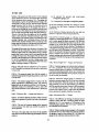
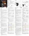
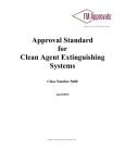
8.5.5 SimulatedCasting Fire
8.5.5.1 General
The tire consists of melted metal poured into the steel
traydescribed
in 8.5.4.1 positioned on a level surface with
8.5.4.1 Construction
an obstruction, formed from a SO ± 5 nun length of steel
Two series of tests arecarried out.Oneserieswill becarried l-beam, 100 mm deep and 100 mm wide, positioned
out in a circular steel pan approximately 540 mm in centrally in the tray, on its side in the attitude of an arch,
diameter and 1SO:i: 10 rnm deep, fittedwith a tightfitting , as shown in Fig. 3.
cover, and with suitable means of handling, moving and
tipping, and with a horizontal thermocouple to be
positioned in the approximate centre of the pan.This pan 8.5.5.2 Fuel
is also used to melt the metal fuel, using a heat source Use 11.3 :i: 0.1 kg of the magnesium alloy described
which does not allow any flames to extend beyond the in 8.5.2.2.
baseof the pan. In the secondseries, melted burning fuel
is poured on a tray approximately 600 rnm x 600 mm 8.5.5.3 Procedure
square and having a depth of (155 ± 5) mm.
Heat the magnesium alloy in the covered melting pan
described in 8.5.4.1 until completely melted. Carefully
8.5.4.2 Fuel
remove thecoverandcontinue to heatuntil thetemperature
Use (1.36:i:: 0.04) kg of sodium for the spill tire, and for reaches 650 :i: 10°C above the melting point if the fuel
the pan firesufficient sodium to give a melted fuel depth does not ignite spontaneously usethe gas torch (see 8.5.2.1)
of(25::i: 1) mm.
to ignite it. Pourthe fuel intothetray,butnotdirectly over
the obstruction. As soon as the burning fuel has spread
8.5.4.3 Procedure
across the tray, the fire can be attacked at the operator's
discretion using the manufacturer's recommended
8.5.4.3.1 SJ'illj1~
extinguishing techniques.
Position the square tray on a flat level surface. Heat the
metal in the covered melting pan until the tempenture is After discharge is completed follow the procedure
520:i:10°C. Carefully remove thecover, al10wing the liquid described In 8.5.2.3.
8.5.4 Shallow LiquidMetal Fires
14
IS 15683 : 2006
I_ 75 -I
I:
100
I
=====:
~----------------~
LI
i
~100-l
1
2
T
T
Key
1- Obstuction
2- Testpan
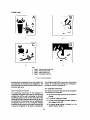
3· Moltenfuel
All dimensions in millimctres.
Flo.
3
OBSTRUCTED MAGNESIUM SPILL FIRE CONFIGURATION
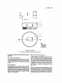
8.6 Electrical Conductivity of Extinguisher Discharge
(Type Test)
8.6.3 Test for Electrical Conductivity
Hanga metal plate,of dimensions 1 m ± 25 mm x 1 m ±
25 mrn, vertically from insulating supports. Connect the
plate to a transformer so that an alternating voltage of
36 % 3.6 kV is established between the plate and earth.
The impedance of the circuit should be suchthat when a
voltageequalto 10percentofthe nonnal primary voltage
is applied to the primary, and the secondary is
short-circuited, the current in the secondary is not less
than 0.1 rnA.
8.6.1 Water-Based Extinguishers
Water-based extinguishers that are marked as suitable for
use on energized electrical equipment fires shall not pass
a current of more than 0.5 rnA when tested as described
in 8.6.3.
8.6.1 Requirements
Test the extinguisher in accordance with 8.6.3. When the
extinguisher is in operation and the metallic plate is live,
the current between the handle or the nozzle and earth
and between earth and the extinguisher shall be no more
than O.S rnA at any time during the complete discharge
duration of the extinguisher.
Mount the extinguisher on an insulating support with the
nozzle fixed 1m fromthecentreof the plate, at right angles
to it and directed towards it. Connect the extinguisher to
theearth. Inthecaseofanextinguisher with a hose connect
it to theearth by connection at thenozzle or in the case of
IS
IS 15683 : 2006
an extinguisher not fitted with a hose, by connection at
the handle.
Measure anycurrentflowing between the extinguisher and
the earth when the plate is live and the extinguisher
discharging.
9 CONSTRUCTION REQUIREMENTS
9.1 High-Pressure Extinguishers
Extinguishers with a service pressure greater than 19 bar
(C0 2) shall have concave base. For carbon dioxide
extinguishers, in case of steel body, it shall conform to
IS 7285 and in case of aluminium-body, 'it shall conform
to IS 15660. Gas cartridge shall conform to IS 4947. The
CO2 gas cartridgeshall be of minimum 60 g.
9.2 Low-Pressure Extinaulshers
9.2. I General Requirements
9.2.1.1 Theserequirements are applicableto extinguishers
having a service pressure (P J not exceeding 19 bar.
9.2.1.2 A portable extinguisher with a charge exceeding
3 kg shallbeconstructed such that it can bestoodvertically
without extra support. Gas cartridge shall conform to
IS 4947.
9.2.1.8.1 Conduct the test on a minimum of three
extinguishers conditioned at S5 °C for 18 h.
9.2.1.8.2 Forstored-pressure type extinguishers, determine
the pressure immediately after taking each extinguisher
out of the oven. For cartridge-operated type extinguishers,
remove each extinguisher from the oven and activate the
cartridge immediately.
9.2.1.8.3 Foreach type of extinguisher thehighest pressure
observed during 9.2.1.8.2 is recorded as the maximum
service pressure (P l1li)'
9.2.2 Burst Test
9.2.2.1 Fill the extinguisher with a suitable liquid and
increasethe pressure at a rate not exceeding (20 ± 2) barf
min until the minimum burst pressure (P.) is achieved.
Maintain this pressure for I min without the cylinder
rupturing. Increase the pressure until ruptureoccurs. The
minimum burst pressure (PJ shall be 2.7 x PmI but in no
case less than 5S bar.
9.2.2.2 The bursting test shall not cause the cylinder to
fragment.
9.2.2.3 The break shall not show any sign of brittleness,
9.2.1.3 Themanufacturer shall ensurethat the weldsshow
that is the edges of the break shall not be radial but shall
be slanting in respect of a diametrical plane and shall
exhibit a reduction in area over their entire thickness.
continuous penetration with no deviation in the weld.
Welds and brazedjoints shall be free from defects which
are prejudicial to the safe use of the cylinder.
9.2.2.4 The break shall not showanycharacterized defect
in the metal.
9.2.1.4 Partsattachedto the bodyoftheextinguishershall 9.2.2.5 The break shall not occur in the weldat a pressure
be manufactured and fitted in a way that minimize . less than 5.4 x P1M or 8 MPa (80 bar), whichever isgreater.
concentrations of stress and corrosion risks. In the case of
welded and brazed parts, the metal shall be compatible 9.2.1.6 During the burst test, no parts shall be ejected
with the cylinder material.
from the extinguisher.
9.2.1.5 The cylinder manufacturer shall obtain the
9.2.3 Crushing Test (Type Test)
certificate for the cast analysis of material supplied.
9..2.1.6 Where plastic components are threaded into
metallic parts they shall be designed to minimize the
possibility of cross-threading. This shall be accomplished
by the use of coarse threads of less than 5 threads fern or
by the use of square-cutthreads.
9.2.1.7 Extinguishers whichare free standingshall either
be fitted witha meansto raise the pressure-retaining part
of the bodyat least5 nun above the floor,or the thickness
of metal in the lowestpressure retaining part or parts of
the body shall not be less than 1.5 times the minimum
thickness of the cylindrical part of the body.
9.2.1.8
Determinat~on
ofmaximum servicepressure (P,J
9.2.3. I Crush a minimum of three extinguishers
perpendicularly to their longitudinal axis, and at their
midpointusingtwo 25 mm thick mandrelswitha radiusat
their apex of )2.5 nun and a width sufficient to extend
beyond the sides of the extinguisher (see Fig. 4). Crush
the cylinder'over a period between 30 s and 60 s. In the
case of extinguishers with a longitudinal weld place, the
weld seam at 90 0 to the support lines. For extinguishers
with central transverse welds, apply the mandrel at 450 to
the weld seam.
9.2.3.2 After the crushing test, till the extinguishers with
water and increase the pressure to- test pressure (P I ). the
extinguishers shall not exhibit any cracks or leaks.
16
IS 15683 : 2006
25
Where
OTis the distanceafter test
o
FIG.
4
is the outside diameterof cylinder
CRUSHING TEST
9.2.4 Permanent Volumetric Expansion Test (Type Test)
It is only for high pressure cylinders. There shall be no
pennanent expansion in excessof 10 percent of the total
expansion of the cylinder when subjected to the test
pressure (Pc) for 30 s. For cylinders that havebeenproofpressure testedpriorto the deformation test, test pressure
shallbe increased by 10 percent'
greater thantheminimum thickness given bythefollowing
formula but in no case lessthan 0.70 mm:
D
.
S=-+k
300
where
S = minimum thickness, expressed in mm;
D = outside diameter of the cylinder or, for noncylindrical bodies, the greatest external diagonal
of the extinguisher body, expressed in mm; and
k = coefficient equal to:
0.45 for D S 80;
0.50 for 80 < D S 100; and
0.70 for D> 100.
NOTE - An acceptable test apparatus is the water jacket test
however othermethods are alsoacceptable.
9.2.5 Pressure Cycling Test (Type Test)
A minimum of two cylinders shall be tested.
An extinguisher cylinder shall sustain, without rupture,
5 000 cycles from 0 to the test pressure (P.) and back to
oat the rate of 6 cycles/min. At the conclusion of testing,
the cylinder shall be subjected to and comply with the
bursttest.
9.2.7 Stainless Steel Cylinders
9.2.7.1 Stainless steeldomes and bottoms shallbe drawn
from fully annealed stock.
9.2.6 ""Ided LowCarbon Steel Cylinder
9.2.7.2 Onlyaustenitic stainless steel having a maximum
carbon content of 0.03 percent shall be used.
9.2.6.1 The cylinder material shall be capable of being
welded and shall contain a maximum of 0.25 percent
carbon, 0.05 percent of sulphur and 0.05 percent of
9.2.7.3 The cylinder shall have a minimum measured
wall thickness greater than the minimum wall thickness
given by the following formula but in no case less than
phosphorous.
9.2.6.2 Fillermaterial shall be compatible with the steel
to give welds with properties equivalent to those specffled
for the base sheet.
O.64mm:
D
600
S=--+k
9.2.6.3 The cylinder shall have a measured thickness
17
IS 15683 : 2006
EXCEPTION -A minimum vertical motion of3 mm isacceptable
foran extinguisher having a gross massof S.4 kg or less.
where
S
D
= minimum wall thickness, expressed in mm;
= outside diameter of the cylinder or, for non-
cylindrical bodies, thegreatest external diagonal
of the extinguisher body, expressed in mm; and
k = 0.3.
9.2.8 Aluminium Cylinders
9.2.8.1 Aluminium cylinders shall be of a seamless
construction.
9.2.8.2 Aluminium cylindersshall have a measured wall
thickness greater than or equal to the minimum thickness
given by the following fonnula but in no case less than
0.71 mm:
D
S=-- +k
80
where
S
= minimum thickness, expressed in mm;
D = outside diameter of the cylinder, or for noncylindrical bodies the greatest external diagonal
of the extinguisher body, expressed in mm; and
k = coefficient equal to:
0.2 for D S 100 mm;
0.3 for D> 100mm.
9.3 Carrying Handle
9.4.3 Amounting bracketshall becapable of withstanding
a static load of five times the fully charged mass of the
extinguisher, whentested in accordance with 9.4.4.
9.4.4 Place an extinguisher chargedto its rated capacity
in the mounting bracket provided with the extinguisher
after the mounting bracket has been secured to a wood
board. Securethe board ina vertical position and applya
static load of four times the full extinguisher mass (or a
total load of 45 kg minus the full extinguisher mass,
minimum) to the top of the extinguisher. Holdthe loadfor
Smin.
9.4.5 A mounting bracketequipped with a strap shall not
permitthe extinguisher to drop to the floorwhenthe strap
clampis opened.The clampreleasingdeviceshallbe ofa
colourcontrasting with thatofthe immediate extinguisher
background and shall be visible. The method of release
shall be obvious when viewing the front of theextinguisher.
9.4.6 A hanger loopshall be located so that the operating
instructions face outward when the extinguisher is
supported by the mounting means.
9.5 Caps, Valves and Closures
9.5.1 Cylindercaps, valvesand closures shallbedesigned
to provide release of pressure before complete
disengagement.
9.3.1 An extinguisher having a total mass of 1.5 kg or
more and having a cylinder diameter of 75 rnm or more
9.5.2 Threaded connections on cylindershallhaveat least
fourfull threadsof engagement and be required to relieve
shallhavea carryinghandle.
pressure with at leasttwofull threads of engagement. Other
. typesof valves,caps and closuresare permissible if they
NOTE - The valve assembly head itself may be considered a
cansatisfy the samerequirements, particularly withregard
handle, provided it meets the requirements of 9.3.2 and 9.3.3.
to recurrent tests and fi lling,
.
9.3.2 A handle shall be not less than 90 mm long for an
extinguisher of 7.0 kg or more total mass and not less
than 75 nun long for an extinguisher of less than 7.0 kg
total mass.
9.3.3 There shall benotlessthan 25 mm clearance between
extinguisher body andthecarrying handle whenthehandle
is in the carrying position.
9.4 Mounting
9.4.1 Each extinguisher intended for wall mounting shall
be provided with a meansof mounting.
9.4.2 A wall mounting hookshallrequire both a horizontal.
and a minimum 6 nun vertical motion to remove the
extinguisher from the wall.
9.5.3 The inside diameter of a filling opening for a
rechargeable type extinguisher shall be no less than
19mm.
9.5.4 An extinguisher collar with external threads shall
have sufficient height so that the cap or valve does not
contactthe dome or bottom with the gasketremoved.
9.5.5 A cap. valves or closure shall withstand the burst
test pressurespecified for the cylinder for ) min without
rupture. For this test, remove or plug pressure relief
devices.
9.5.6 The edgesand surfacesof a fireextinguisher and its
mounting bracker.shall not be sufficiently sharp to
constitute a risk of injury to persons during intended use
or while perfonning maintenance.
18
IS 15683 : 2006
9.6 Safety Devices
9.8.1.1 Plasticscomponents of portablefireextinguishers
shall comply with the followingrequirements.
9.6.1 High pressure cylinders and cartridges shall be
provided with a safety device in accordancewith national
regulations.
9.6.2 There are no compulsory safety systems required
for low-pressure extinguishers. However, ifsuch a system
is used,it must be appropriately sizedand positioned. The
operatingpressure of the device shall not exceed the test
pressure (P,) norbe less than the maximum service pressure
(P ml)'
The test and conformity checks shall be carried out on
components which correspond to the mass-produced
components in respect of the material used, the form and
the method of manufacture.
9.8.1.2 It is recommended that the plastic used, be
identifiable at all times.
Any change in the material, the form, or the method of
manufacture requiresa new test.
9.7 Manufacturing Tests
9.7.1 Low-Pressure Cylinders
9.8.1.3 It is necessaryto have access to data supplied by
the manufacturer relating both to the material itself and
the manufacturing procedures.
9.7.1.1 At least one cylinder from each batch of 500 or
less shall be subjected to the burst tests. If the test results
are not acceptable, randomly select five additional
cylindersfrom the same batch and repeat the tests. If one
of the cylinders does not pass the test,the batch is rejected
and madeunserviceable. Atthe optionof the manufacturer,
the burstand crushingtest may be conductedon the same
cylinder.
9.8.1.4 Toverifythe attachmentof plasticpartsfollowing
the air-ovenageing,ultraviolet lightexposure and impactresistance tests,attachthe plasticpart(s)to an extinguisher
and then subject the assemblyto the appropriate pressure
test.
9.7.1.2 Eachcylindershallbe subjected to thetestpressure
(PI) for 30 s, without leakage, failure or visible
9.8.2.1 Burst strength
deformation.
9.8.2.1.1 Conduct burst tests at three temperatures as
describedbelow:
9.7.2 Leakage Test (Type Test)
Subject at least three components to the burst test in
accordance with 9.2.2 using an appropriate liquid at
temperatures of 27±5°C, the minimum recommended
operation temperature marked on the extinguisher
(see 7.1), and 55 ± SoC. Increase the pressureat a rate of
2 ± 0.2 MPa/min.
Eachstored-pressure and carbon dioxideextinguisherand
gas cartridge shall be subjected to a leakage test and
complywith the followingrequirements:
a) Stored-pressure extinguishers fitted with a gauge
as specified in 7.4.1.3, the leakage rate shall not
exceed a rate of loss of pressurizing content
equivalent to 5 percent per annum of service
pressure.
b) Gas cartridges and stored-pressure extinguishers
without gaugesas specified in 7.4.1.2, the maximum
loss of contents per annum shall not exceed the
following:
1) for extinguishers: 5 percent or SO g, whichever
is less, and
2) for 'gas cartridges: 5 percent or 7 g, whichever
is less.
c) Carbondioxide extinguishers the maximum lossof
contents shall not exceed 5 percent per annum.
NOTE - All stored-pressure extinguisher soapsolution test be
conducted to check leakage as a routine test.
9.8 Requirements for Plastics Components
9.8.1 General Requirements
9.8.2 Requirements/orNormallyPressurized Components
9.8.2.1.2 The burstingpressurebeforeandaftertheageing
and ultravioletlightexposuretest shall be at leastequal to
the minimum burst pressure (P b )
9.8.2.2 Air-oven ageing
9.8.2.2.1 Subjectat leastthree components to accelerated
ageing in an oven at 100°C for 180 days. Fit the
components with adapters to apply normal assembly
stresses.
9.8.2.2.2 Following the exposure, condition the
components for S h at 27 ± SoC and subsequently inspect
them for cracking. No cracking shall be permitted,
9.8.2.2.3 Subject the components to the burst test in
accordancewith 9.2.2 at 27 ± 5 °C using a suitableliquid
at a rate of pressure increase of 2 :J: 0.2 MPa/min. The
bursting pressure (P b) shall be at least equal to that
specified for the cylinder.
19
IS 15683 : 2006
9.8.3 Ultraviolet Light Exposure
shall then becapable ofwithstandingthe test pressure (PI)
without bursting.
9.8.3.1 Subject at least six components to an artificial
weathering test in accordance with 9.8.3.4 for 500 h and
then conditionthem for S h at 20 % SoC.
9.8.5 Normally Non-pressurized Components
9.8.5.1 Subject plastic extinguisher components which
withstand pressure upon extinguisher operation to the
burst, air-ovenageingand impact-resistance tests.The airoven exposure is either 100°C for 70 days or 87°C for
180 days at the manufacturer's choice.
9.8.3.2 Following the exposure, inspect the samples for
cracking. No cracking shall be permitted,
9.8.3.3 Subject the components to the burst test in
accordance with 9.2.2 at 20 ± S °C using a suitable liquid
at a rate of pressure increase of 2 :l: 0.2 MPa/min. The
bursting pressure (P b) shall be at least equal to that
specified for the cylinder.
9.8.5.2 External plastic components shall comply with
the ultraviolet light test.
9.8.6 Test for Exposure to Extinguishing Medium
9.8.3.4 Use two stationary enclosed carbon-arc lampsto
obtain the ultraviolet light. The arc of each lamp is to be
fonned betweentwo vertical carbon electrodes, 12.7 mm
in diameter, located at the centre of a removable vertical
metalcylinder, 787 mm in diameter and 450 mm in height.
Enclose eacharc in a clear borosilicate-glass globe.Mount
the samples vertically on the inside of the revolvable
cylinder, facing the lamps, and revolve the cylinder
continuously around the stationary lamps at I rev/min.
Providea systemofnozzles so as to spray each sample,in
tum, with water as the cylinder revolves. During each
operatingcycle (total of20 min), expose each sample to
the light and water spray for 3 min and to the light only
for 17 min. Maintain the air temperature within the
revolving cylinder of the apparatus during operation at
63 ± SoC.
9.8.6.1 Thereshallbeno damageto polymeric siphon tubes
which have been conditioned in accordance with 9.8.6.3,
when installed in test extinguishers and subjected to the
mechanical resistance test described in 7.5.
9.8.6.1 Following conditioning inaccordance with9.8.6.3,
ring samples cut from polymeric siphon tubes shall not
exhibitdegradation in excess of 40 percentof the original
tensile or ring crushing strength value.
9.8.6.3 Place complete siphon tubes in contact with the
extinguishing (water based only) media with which they
are to be used. Totally cover or immerse ring samples,
12.7mmwide,cut from unaged siphontubes inthe media.
Ensure thesamplesdo nottoucheachotheror thecontainer
holding the media and samples. Place the container of
media, with the samples in place, in a preheated oven at
90 ± 5 °C for 210 days. After the test exposure, cool the
samples in air at 27 ± S °C for at least 24 h before any
. tests or dimensional measurements are conducted. Subject
the ring samples to a crush test between two parallel flat
plates using a testing machine capable of applying a
compressive load at a uniform rate of 5 mm/min and
recording the load versus the deflection. If the nature of
the material is such that meaningful test resultscannot be
obtained, other tests, such as tensile tests, may be
conducted.
Alternatively, test by usinga Xenonarc source,fora period
of 500h may becarriedout. Usethe following conditions:
a) 65::l: 3°C black panel temperature;
b) 50:l: 5 percent relative humidity;
c) spray cycle: 102 min dry interval, 18 min water
spray; and
d) total dose of exposure : I GJ/m 2 (500 h at
SSO W/m 2) .
9.8.4 Impact Resistance
9.8.4.1 Mount at leastfoursamplessubjected to theageing
test (see 9.8.2.2) (two with and two without the safetylocking device engaged), and pressurize the extinguisher
cylinder to the maximum service pressure (P l1li) with
nitrogen after being tilled 9S percent with a water and
anti-freeze solution. Test the samples at -27 ± SoC or at
the minimum recommended operation temperature,
whichever is lower. The test is carried out as described
in 7.5.1.
9.9 Hose Assemblies (Batch Test)
9.9.1 Extinguishers with a charge greater than 3 kg shall
be equipped with a hose assembly having a minimum
length of400 mm.
9.9.2 The hose and coupling system shall function
throughoutthe operatingtemperaturerange,and coupling
systems shall be designed and fitted in such a way that
they cannot damage the hose.
9.9.3 The burst pressure of a hose assemblyfitted with a
shut-offnozzleshallbe equal to or greater than appropriate
9.8.4.2 No hazardous changes shall occur to the valve
assembly such as splinters, fractures or cracks. The valve
20
IS 15683 : 2006
value below. The test pressure shall be established by
increasing the pressure to the minimum allowable burst
pressure in a time no less than 30 s, maintaining that
pressure for 30 s during which failure shall not occur and
then increasing the pressure until failure.
Table 10 Force or Energy Required to
Operate the Extinguisher
(Clause 9.10)
For all types except CO 2 and clean agent extinguishers:
a) 2.0 times the maximum service pressure (P rm)' the
test being carried out at 7 ± 5 °C; and
Type of
Maximum Force
Operation
Required
N
J
(I)
(2)
(3)
Withone finger
With full hand
With impact (strike knob)
. b) 1.5 times the maximum service pressure (P ms), the
test being carried out at 55 ± 2 °C.
II
Energy
100
20011
2
For carbon dioxide extinguishers. this maximum force may be
increased to 300 N.
For CO2 and clean agent extinguishers:
a) 1.S times the maximum service pressure (P ms)' the
tes~
The safety-locking pin may be on the reverse
side of the extinguisher if pictographic operating instructions on
the front illustrate the intended methodof operation.
EXCEPTION -
being carried out at 27± 5°C; and
b) 1.25timesthe maximumservice pressure (P ms), the
test being carried out at 55 ± 5°C.
9.11.4 If the safety.. locking device is attached to the
extinguisher by a chain or similar device, the chain shall
be attached so as to not interferewith the discharge stream.
9.9.4 A hose assembly without a shut-ofT nozzle shall be
capable of withstanding, without leakage, a hydrostatic
pressure equal to the extinguisher test pressure, (PI) held
for at least 30 s.
9.11.5 A tamper indicator such as a seal shall be provided
to retain the safety.. locking device in place and to indicate
tampering with or use of the extinguisher.
9.10 Method of Operation (Batch Test)
9.] t.6 The tamper indicator shall be constructedso that it
must be broken to operate the extinguisher. The force
required to break the tamper indicator shall not exceed
70N.
The extinguisher shall be operated by piercing, opening
and/or breaking a sealing device, thus releasing its
contents.Extinguishersshall operate without inversion. It
shall not be necessary for any movement of the actuating
mechanismto be repeated in order to initiate discharge of
the extinguisher. The forces or the energy necessary to
operatethe extinguisher shall not exceed the values given
in Table 10 for temperatures up to 55°C.
If the tamper indicator is broken by the action
neededto start discharge of the extinguisher, or ifan internal load
is continuously applied to the release mechanism, the force
required to accomplish discharge or release of the internal load
may exceed 70 N, but shall not exceed 140 N.
EXCEPTION -
The energy of 2 J is obtained by allowing the 4 kg mass
used in the mechanical resistance (impact) test described
in 7.5 to fall from a height of 50 mm, The impact shall be
applied in the direction of the operating mode.
9.12 Requirements for Pressure Gauges and Indicators
for Low-Pressure Extinguishers
9.12.1 General
9.11 Safety-Locking Devices (Batch Test)
9.12.1.1 A rechargeable extinguisher of thestored-pressure
type (except carbon dioxide) employing a single chamber
for both the extinguishing medium and the expellant gas
shallbe equipped with a pressure gaugeto showthe amount
of pressurein the chamberregardless if the valveis opened
or closed.
9.11.1 The operating mechanism shall be provided with a
safetydeviceto prevent inadvertentoperation.The release
ofthe safety device with tamper indicator shall involvean
operation distinct from that of the operation mechanism
and shall require a force of no less than 20 N but not
exceeding 100N. It shall be possible to determinewhether
the apparatus may have been operated.
9.12.1.2 The operable pressure range of the gauge shall
reflect the operating temperature-pressure relationshipof
the extinguisher (see 7.1).
9.11.2 The safety-locking device shall be made of a
corrosion-resistantmaterial.
9.12.1.3 The pressure gauge face shall indicate the
appropriate units for which the gauge is calibrated, such
as bar, or kPa, or any combination of pressure units.
9.11.3 The safety-locking pin or other device shall be
visible from the front of the extinguisher when the
extinguisher is mounted in its mounting bracket.
9.11.1.4 The maximum indicated gauge pressureshall be
21
IS 15683 : 2006
between 1SO percent and 250 percent of the indicated
service pressure (P s>at 20°C, but not lessthan 120percent
of the maximum service pressure (P ml>' The gauge dial
shallindicate, in green,the operablepressurerangeof the
extinguisher. The zero, service, and maximum indicated
gauge pressures shall be shown in numerals and with
marks. The background of the gauge face above a
horizontal linethroughthe lowestrequiredmarkings shall
be red.The arc of the dial from the zero pressurepoint to
thelowerendof the operablerange shall read 'Recharge'.
The arc of the dial from the higher end of the operable
range to the maximum indicated pressure shall read
'Overcharged'.All numerals, letters,and characters in the
recharge, operable, and overcharge portions of the dial
shallbe white. Pointersshall be yellow, and the tip of the
pointershallend in the arc of the pressureindicating dots,
and shall have a maximumtip radius of 0.25 mm.
a) ::1:4 percent for powder and water-based
extinguishergauges; and
b) ± 8 percent for clean-agentextinguishergauges.
At the zero pressure mark the error shall not exceed
12 percent, nor fall below 0 percent of the service
pressure (P.>.
At the maximum indicated pressure the error shall not
exceed ± 15 percent of the service pressure (P ,.).
9.11.2.3 The pressure gauge or indicator is to be
installed on a deadweight gaugetesteror a pipingapparatus
with a master gauge having an accuracy of no less than
0.25 percent.The pressurizingmediummay be oil, water
nitrogen, or air, but all tests on a given type of gauge are
to be conducted using the same medium. The pressureis
to be appliedto thegauge undertest in uniform increments
until the upper limitof the gauge is reached. The pressure
then is to be reducedin the same increments untilthezero
point is reached. The pressure applied, the gauge or
indicatorreading,and net error are to be 'recorded foreach
incrementin both the increasingand decreasingpressure
conditions.
The lengthof the pointer from the point of rotationof the
pointer to the tip, measured at the zero pressure point,
shall be at least 9 mm for extinguishers having a charge
greaterthan2 kg or at least6 mm for extinguishers having
a charge of 2 kg or less. The length of the arc from zero
pressureto the indicatedservice pressure shall be at least
12 mm for extinguishers having a charge greater than
2 kg or at least 9 mm for extinguishers filled with clean
agentsor having a charge of 2 kg or less.
9.12.3 Burst Strength Test- Gauges and Indicators
9.12.3.1 A pressuregauge or an indicatorshallwithstand,
for I min, a pressure of six times the indicated service
pressurewithoutrupture. In addition, if the Bourdontube
or pressure-retaining assembly bursts at a pressure less
thaneight timesthe indicatedservicepressure, no partsof
the device shall be discarded.
9.12.1.5 The mark used to indicate the service pressure
at 27°C should be no less than 0.6 mm and no more than
1.0mm wide.
9.12.1.6 The pressure gauge face shall be marked to
indicate theappropriate extinguishing medium withwhich
it can be used.
9.12.1.7 The pressure gauge shall be marked with the
gauge manufacturer's identifying mark. The pressure
gaugeshall also be marked according to the following, if
applicable, using a line extending as wide as, and of the
same stroke thicknessas, the manufacturer's identifying
mark.
,9.12.3.2 Attach the sample gauge or indicator to a
hydraulic pressure pump after all air has been excluded
from the test system. Place the sample in a test cage and
apply pressure at a rate of approximately 2.0 MPalmin
until therequired testpressure isreached. Holdthepressure
is to be held at this point for I min, then increase the
pressure until rupture occurs or eight times the indicated
service pressure is reached, whicheveroccurs first.
9.12.2 Calibration Test- Gauges and Indicators
9.12.4 Overpressure Test - Gauges
9.12.2.1 An indicatorshallbe accurateto within4 percent
oftheservice pressure (P) at thelowerlimitof theoperable
range.
9.12.4.1 The difference in readings of indicated service
pressure, before and after a pressure gauge has been
subjected for 3 h to a pressure of 110 percent ,of the
indicated gauge capacity, shall not exceed 4 percent of
the indicatedservice pressure.
9.12.1.2 The error of a pressure gauge at the indicated
service pressure (P,> shall not exceed :1:4 percent of
servicepressure.
9.12.4.2 Subject sample pressure gauges to the required
tesf pressure for 3 h. Then release the pressureand allow
the gauges to stand at zero pressure for 1 h. Subject the
gaugesto the calibration test described in 9.12.2.
The error at the upper and lower limits of the operable
range shall notexceedthefollowing percentages of service
pressure:
22
IS 15683 : 2006
9.12.S Water Resistance Test- Gauges and Indicators
Agauge or indicator for use on an extinguisher shall remain
watertight after being immersed at a depth of 0.3 m in
water for 2 h, and after being subjected to the salt-spray
corrosion test (see 7.6.1).
crushing when 25 kg is applied to its extremity for 5 min
immediately after having completely discharged the
extinguisher throughthe hom.
Subjectthe hom to the following test:
'a) Condition the hom at S5 °C for 18 h;
b) Attach the hom to a fully chargedextinguisher;
c) Discharge the extinguisher with the valve fully
open;
9.12.6 Leakage Test- Gauges and Indicators
9.12.6.1 A pressuregauge or indicatorshall not leakat a
rate in excessof I )( 10-6 em)/s whenthe gaugeor indicator
(including a pin-type indicator) is exposed to a pressure
equivalent to the intended service pressure of the
extinguisher at 20°C.
d) Subject the hom to a static load of 2S kg using a
circular contact surface of 50 mm diameter for
5 min applied at the end of the hom: and
e) Checkthat the hom does not showanyevidence of
crackingor breakage.
9.12.6.2 A leak detection apparatus and leak standard
are to be usedto verifycompliance withthe requirements
specified in 9.12.6.1. The leak detection apparatus is to
be capableof signaling, and the leak standardcapable of
generating, a leakagerate of 1 x 10⁻⁶ ern'Is.
10 MARKING AND COLOUR
10.1 Colour
9.12.6.3 Apply a pressure equivalent to the intended
working pressure of the extinguisher at 27°C to each of
The recommended colour for extinguisher bodies is red
conforming to shade No. 536 or 538 of IS 5. The paint
shall conform to IS 2932.
twelve samplegauges or indicators. Subject each sample
gauge or indicator, other than a pin-type indicator, to a
leak test by checking all pressurized components for
leakage inorderto verify compliance withtherequirements
givenin 9.12.6.1. Testeach pin-typeindicatorfor leakage
by checking the opening sealed by the indicator for
leakage. None of the samples shall exhibit leakage at a
rate in excessof 1 x 10⁻⁶ ern'Is.
10.2 Marking
NOTE - Anexample of the layout formarking isgiven in Fig. S.
10.2.1 General
10.2. J.J The operating, recharging, and inspection and
maintenance instructions shall be in the form of an etched
or embossed metal nameplate or band, or an acceptable
pressure-sensitive nameplate attached to the side of the
extinguisher body, or inthe form of silk-screening of paint
directly .on the extinguisher body. The marking shall
identify -the extinguisher as to type of media and shall
include the manufacturer's name and model number and
the rating and classification of the fire extinguisher.
9.12.7 Plastics Components - Gauges and Indicators
Plastic components of gauges and indicators shall meet
the requirements given in 9.8.
NOTE - Alternatively, forgauges, manufacturer's certificate or
calibration certificate from anyrecognized agency shall be made
available.
9.13 Dip-Tubes and Filters Extingulshen
Water-Based
10.2.1.2 The marking shall include a sequential serial
number.
9.13.1 Thedip-tube andfilterof water-based extinguishers
shall be constructed of materials resistant to the
extinguishin, medium (see 9.8.6).
10.2.1.3 The year of manufacture, or the lasttwodigitsof
the calendar year, and the factory test pressure shall be
permanently marked into the extinguisher body or nontransferable nameplate. Extinguishers manufactured inthe
last three months of a calendar year may be marked with
the following year as the date of manufacture, and
extinguishers manufactured in the first three months of a
calendar year may be marked with the previous year as
the date of manufacture.
9.13.2 The extinguishing medium from water-based
extinguishers shallbedischarged througha filter. Thefilter
shall be placed upstream of the smallest section of the
discharge passage. Each orifice of the filter shall have an
area less than that of the smallest cross-section of the
discharge passage. The total area of the combined tilter
orifices shall be at least equal to five times the smallest
section of the discharge passage.
9.14 Special Requirements for CO 2 Extinguishers
(1)'pe Test)
The extinguisher hom shall be constructed to withstand
, 10.1.1.4 Themarking shall include a reference to therange
of temperatures at which the extinguisher is usable, such
as· ' Acceptable to use at temperature from ... to ... or the
equivalent.
t
23
~
tv
FOR INDUSTRIAL USE.
RECORD : RECORD MAINTENANCE AND
RECHARGE DATES ON ATTACHED TAG.
ASSEMBlY.
RECHARGE: CO2 CHARGE IS 2 kg. FULL MASS
STAMPED ON VALVE BODY INCLUDES HORN
USE : ~FTER ANY USE RECHARc;;e IMMEDIATELY.
oorrrc
PARTS. CHECK HORN FOR OBSTRUCTIONS.
HYDROSTATIC RETEST TO
REQUIREMENTS EVERY 5 YEARS.
EXCEEDS 0.2 kg. REPlACE ANY DAMAGED
MAINTENANCE: EXAMINE CAREFULLY EVERY
12 MONTHS TO ENSURE EXTINGUISHER IS
OPERABLE. RECHARGE IF MASS lOSS
as
INSPECTION : INSPECT MONTHLY CHECK
THAT EXTINGUISHER IS CHARGED.
UNDAMAGED AND SEAL IS INTACT .
MAKE SURE HORN
UNOBSTRUCTED.
2 KG CARBON-DIOXIDE FIRE EXTINGUISHER
FIG.
5
m
SWEEP SIDE TO SIDE
?
EXAMPLE OF LAYOlIT MARKING FOR AN EXTINGUISHER
~1J
--(m
@
SQUEEZE LEVER
.~=d
AIM AT BASE OF FIRE
START BACK 3
HOLDUPRIGHT
PULL RING PIN
0
CD
INSTRUCTIONS
MFG. NAME
~
MFG. ADDRESS
322
MODEL
SUITABLE FOR USE AT TEMPERATURES
FROM -3Q·C TO SS·C
PRESSURETESTED TO 20 MPa
2kg CARBON DIOXIDE FIRE EXTINGUISHER
MEETS ceo 22(7272)
SERIAL NO. XX-XXXXX
CLASSIFICATION 21-8
CARBON-DIOXIDE FIRE EXTINGUISHER
APPROVAL
MARK
~
N
=
=
CM
Of)
«A
0\
....
....r:n
IS 15683 : 2006
10.2.1.5 The following applicable statement or the
equivalentshall be included in the marking:
a) For rechargeable extinguishers: •Recharge
immediately after any uset; and
10.2.2.3 The operating instructions shall face outward
and cover no more than a 1200 arc on the extinguisher
body. The marking required in 10.2.2.4 and 10.1.3 shall
together occupy a minimum surface area of75.0 em' for
an extinguisherhaving a diameter greater than 80.0 mm
and 50.0 em' for and extinguisher having a diameter of
80.0 mm or less.
b) Fordisposable extinguishers: 'Discardimmediately
after any uset •
10.2.1.6 The gas cartridge shall be permanently marked
10.2.2.4 The operating instructions shall be arranged as
with:
follows:
a) Empty mass in g,
a) Word 'INSTRUCTIONS' shall be at the top of the
nameplate. The minimum letter height shall be
6.0 mm for an extinguisher having a diameter
greater than 80.0 mm and 5.0 mm for an
extinguisherhaving a diameterof80.0 mmor less.
As an option, the words FIRE EXTINGUISHER
or EXTINGUISHER may be added to the word
INSTRUCTIONS;
b) Nominal full mass in S,
c) Year of manufacture,and
d) Name or code of the manufacturer.
The above informationmay be placed on the cartridge in
the form of a decalcomania transfer if the cartridge is
mounted on theoutsideof the extinguisher mediachamber.
If the cartridgeis mounted inside the mediachamber, this
information shall be stenciledor stampedon thecartridge.
b) Operating instructions shall be in the form of
numerically sequenced pictographs. A single
pictographmay include two instructions;
10.2.1.7 The marking on each extinguishershall include
itsexactgrossmassor minimum andmaximum grossmass,
which may be expressed by a tolerance. The gross mass
shall include the mass of the charged extinguisher and
discharge assembly.
c) Sequence of pictographs shall illustrate, with
pictures, the recommended actions necessary for
intendedoperationofthe extinguisher. Words may
be added. The sequenceshall be as follows:
1) making ready the extinguisher by disengaging
the safety-lockingdevice,
10.2.1.8 BIS certification marking
The extinguishermay also be marked with the Standard
Mark.
2) aiming the extinguisher at the base of the fire,
including the recommended distance from the
fire at which to begin discharge, and indicating
the intended operating attitude of the
extinguisher,
The use of the Standard Mark is governed by the
provisions of the Bureau ofIndian Standards Act, 1986
and the Rules and Regulations made thereunder. The
detailsof conditionsunder which a licence for the use of
the Standard Mark may be granted to manufacturers or
producers may be obtained from the Bureau of Indian
Standards.
3) taking whatever action necessary to initiate
operation of the extinguisher, and
4) describingthe intended. method of applyingthe
extinguishingmedia on the fire.
10.2.2 Operating Instructions
10.2.2.5The extinguishershallbe marked withletters' A',
'B' and 'C' indicatingtheir suitability for respective class
of tires as laid down in IS 2190 and numerical indicating
size of fire such 2A and B etc.
10.2.2.1 For the purpose ofapplying the requirements of
thissection, the •operating instructions' aredefined asthose
necessary to accomplish intended discharge of the
extinguishing media includingany warnings. An example
of the layoutmarking is given in Fig. 6.
10.2.3 UseCodeSymbols
10.2.3.1 Usecodesymbols(see Fig.6) shall be positioned
directly below the operating instructions. A written
description for each use code symbol may be includedas
part of the code in letters having a minimum height of
lOmm.
10.2.2.2 Clean-agentfire extinguishersshall contain the
following warning or equivalent as part of the operating
instructions:
WARNING - The concentrated agent when applied to the tire
canproduce toxicby-products. Avoid inhalation of thesematerials
by eVlCuatina and ventilatina the area. Do not use in confined
.paces of less thanXXX cubicmetres per extinguisher.
10.2.3.2 Use code symbols shall be placed on the
extinguisher for those types of fires for which the
extinguisher is classified. For those classes of fires for
whichthe extinguishersis not intendedfor use because of
NOTE - XXX is the volume iD cubic metres correspondina to
the..ent's LOAEL timesthe nominal charge of the extinguisher.
2S
IS 15683 : 1006
1
2
c
...
3
4
Key
1. Class A : Ordinary solid material fires
2. Class B : Flammable liquid fires
3. Class C : Gas and vapour fires
4. Class 0 : Combustible metalfires
FlO.
6
USE CODE SYMBOLS
potential injuryto theoperator, the usecodesymbols with
a redslash shall also be placedon the extinguisher. The
red slash shall befrom the top leftcomer ofthe symbol to
the bottom rightcomer.
10.2.4 Recharging Instructions
The recharging instructions on the marking of a
rechargeable extinguisher shall state the intended mass
and agent that shall be used in recharging, the intended
expellant gas pressure or the use of a comet and a fully
charged gascartridge. Reference shallbemade to useonly
the manufacturer's replacement parts in recharging the
extinguisher. However, in lieu of detailed recharge
instructions, these instructions may simply instruct theuser
to return the extinguisher to the dealer or manufacturer
forrecharging, using thefollowing words or theequivalent:
"Return to an authorized recharger for recharging in
accordance with Service Manual No... ".
I0.3 Inspection Instructions
The inspection instructions shall statethatthe extinguisher
is to be checked to ensure that:
a) The sealsand tamperindicators are not broken or
missing;
b) It is full (by weighing or lifting);
c) It is not obviously damaged, corroded, leaking or
has a clogged nozzle; and
d) Its pressure gauge reading or indicator is in the
operable rangeor position.
26
IS 15683 : 2006
11 MANUALS
a) Contain necessary instruction, warnings, and
cautions, a description of servicing equipment, and
a description of recommended operations for
intended servicing,
11.1 User Manual and Service Manual
A user manual shall be provided with each extinguisher.
This manual shall contain the necessary instructions,
warnings, and cautions for the intended installation,
operation and inspection of the extinguisher. The manual
shall alsoreference the manufacturer's service manual for
maintenance and recharging of the extinguisher.
b) Provide a list of part numbers of all replaceable
parts; and
c) Indicate that the pressure gauge attached to the
extinguisher shall not be used to determine when
the intended service pressure hasbeen reached. and
a pressure regulator shall be used if the pressure
service is a tank of high pressure gas.
Themanufacturer shallprepare a service manual foreach
model fire extinguisher. It shall be made available upon
request and shall:
ANNEXA
(Clause 2)
LIST OF REFERRED INDIAN STANDARDS
[SNo.
5 : 1994
Title
/SNo.
Colours forready mixed paints and
enamels (fourth revision)
mechanical foam for the fire
fighting
1708(Part 1) : 1986 Method of testing of small clear
specimens of timber: Part 1
Determination of moisture content
(second revision)
2190: 1992
2932: 2003
TItle
6910: 1985
Selection, installation and
maintenance of first-aid fire
extinguisher - Code of practice
(secondrevision)
Method of testing corrosion
resistance of electroplated and
anodized aluminium coatings by
acetic acid salt spray (AAS) test
(first revision)
7285 : 1988
Enamel, synthetic, exterior;
a) undercoating, b) finishing Specification (thirdrevision)
Specification for seamless steel
cylinder for permanent and high
pressure liquefiable gases (second
revision)
7673 : 2004
Fire fighting equipment Glossary of terms (first revision)
14609 : 1999
Dry chemical powder for fighting
A, B,C Class fires - Specification
4308: 2003
Dry chemical powder for fighting
B andC classfires - Specification
(second revision)
4861 : 1984
Specification for dry powder for
fighting fires in burning metals
(first revision)
15222: 2002
Carbon dioxide as fire
extinguishing media for fire
protection - Specification
4947: 1985
Specification forgascartridges for
use in tire extinguishers (second
revision)
15493 : 2004
Gaseous fire extinguishing systems
- General requirements
15660: 2006
4989: 1985
Specification forfoam concentrate
(compound) for producing
Refillable transportable seamless
aluminium alloy gas cylinder Specification
27
Bureau of Indian Standards
SIS is a statutory institution established under the Bureau of Indian Standards Act, 1986 to promote
harmonious development of the activities of standardization, marking and quality certification of goods
and attending to connected matters in the country.
Copyright
SIS has the copyright of all its publications. No part of these publications may be reproduced in any form
without the prior permission in writing of BIS. This does not preclude the free use, in the course of
implementing the standard, of necessary details, such as symbols and sizes, type or grade designations.
Enquiries relating to copyright be addressed to the Director (Publications), BIS.
Review of Indian Standards
Amendments are issued to standards as the need arises on the basis of comments. Standards are also reviewed
periodically; a standard along with amendments is reaffirmed when such review indicates that no changes are
needed; if the review indicates that changes are needed, it is taken up for revision. Users of Indian Standards
should ascertain that they are in possession of the latest amendments or edition by referring to the latest issue of
'BIS Catalogue' and 'Standards: Monthly Additions'.
This Indian Standard has been developed from Doc: No. CED 22 (7272).
Amendments Issued Since Publication
Amend No.
Date of Issue
Text Affected
BUREAU OF INDIAN STANDARDS
Headquarters:
Manak Bhavan, 9 Bahadur Shah Zafar Marg, New Delhi 110 002
Telephones: 2323 01 31, 2323 33 75, 2323 94 02
Regional Offices :
Telegrams: Manaksanstha
(Common to all offices)
Telephone
Central
: Manak Bhavan, 9 Bahadur Shah Zafar Marg
NEW DELHI 110002
Eastern
: 1/14 C.LT. Scheme VII M, V. I. P. Road, Kankurgachi
KOLKAl'A 700 054
Northern
: sea 335-336, Sector 34-A, CHANDIGARH 160 022
Southern
: C.LT. Campus, IV Cross Road, CHENNAI 600 113
2254 12 16, 2254 14 42
{ 2254 25 19, 2254 23 15
Western
: Manakalaya, E9 MIDC, Marol, Andheri (East)
MUMBAI 400 093
{ 2832 92 95, 2832 78 58
2323 76 17
{ 23233841
2337 84 99, 2337 85 61
{ 2337 8626,2337 91 20
260 3843
{ 26092 85
2832 78 91,2832 78 92
Branches: AHMEDABAD. BANGALORE. BHOPAL. BHUBANESHWAR. COIMBATORE. FARIDABAD.
GHAZIABAD. GUWAHATI. HYDERABAD. JAIPUR. KANPUR. LUCKNOW. NAGPUR.
NALAGARH. PATNA. PUNE. RAJKOT. THIRUVANANTHAPURAM. VISAKHAPATNAM.
Printed at Prabhat Offset Press. New Delhi-2