1
96171E
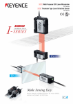
Digital Photoelectric Sensor
PS-N10 Series
User's Manual
Read this manual before use.
Keep this manual in a safe place for future reference.
Introduction
This manual describes the basic operations and hardware functions of the PS-N10 Series.
Read this manual carefully to ensure safe performance and function of the PS-N10 Series.
Keep this manual in a safe place for future reference.
Ensure that the end user of this product receives this manual.
Symbols
The following symbols are used in this manual to alert you to matters concerning the
prevention of injury and product damage.
Always read these sections.
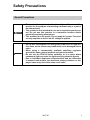
DANGER
It indicates a hazardous situation which, if not avoided, will result in
death or serious injury.
WARNING
It indicates a hazardous situation which, if not avoided, could result
in death or serious injury.
CAUTION
Failure to follow the instructions may lead to minor or moderate
injury.
NOTICE
Failure to follow the instructions may lead to product damage as
well as property damage.
Important
Indicates cautions and limitations that must be followed during
operation.
Point
Indicates additional information on proper operation.
Reference
Indicates tips for better understanding or useful information.
Indicates reference pages.
Safety Precautions
General Precautions
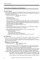
WARNING
NOTICE
• This product is only intended to detect objects. Do not use this
product for the purpose of protecting a human body or a part of
the human body.
• This product is not intended for use as an explosion-proof product. Do not use this product in a hazardous location and/or
potentially explosive atmosphere.
• This product uses DC power. Do not apply AC power. The product may explode or burn if an AC voltage is applied.
• Do not wire the amplifier line along with power lines or high-tension lines, as the sensor may malfunction or be damaged due to
noise.
• When using a commercially available switching regulator,
ground the frame ground terminal and ground terminal.
• Do not use the PS-N10 Series outdoors, or in a place where
extraneous light can enter the light-receiving element directly.
• Due to individual dispersion characteristics and the difference
in sensor head models, the maximum sensing distance or displayed value may not be the same on all units.
96171E
1
Safety Precautions
Precautions on Regulations and Standards
CSA Certificate
PS-N10 series complies with the following CSA and UL standards and has been certified by CSA (Class 2252 05 / Class 2252 85). (CSA mark is attached only to the sensor amplifier certified by CSA.)
• Applicable standard: CAN/CSA C22.2 No.61010-1
UL61010-1
Pollution Degree: 3
Overvoltage Category: I
• Use the following power supply.
CSA/UL certified power supply that provides Class 2 output as defined in the CEC
(Canadian Electrical Code) and NEC (National Electrical Code), or CSA/UL certified power supply that has been evaluated as a Limited Power Source as defined in
CAN/ CSA-C22.2 No. 60950-1/UL60950-1
• Use this product at the altitude of 2000 m or less.
• Indoor use only.
• The sensor head cable and the sensor head connection cable must be installed
with avoiding mechanical damage (e.g.: crushing).
• The power/input-output cable for amplifier unit is for internal wiring only.
• The following cables are rated 30 V.
- sensor head cable
- sensor head connection cable
- power/input-output cable for amplifier unit
Install these cables where it is separated from the circuit over 30 V.
CE Marking
Keyence Corporation has confirmed that this product complies with the essential
requirements of the applicable EC Directive, based on the following specifications.
Be sure to consider the following specifications when using this product in a member
state of the European Union.
● EMC Directive (2004/108/EC)
• Applicable standard
EMI : 60947-5-2, Class A
EMS : 60947-5-2
• When connecting with the NU-CL1, always install in a conductive enclosure (control panel, etc.), and wrap a ferrite core (E04SR401938 manufactured by Seiwa
Electric Mfg. Co., Ltd.) one turn around the sensor head cable.
• When extending the Sensor Head Cable of the PS-47(C)/49(C)/05/52(C)/55(C)/56/
58, cover the entire Sensor Head Cable with conductive piping (for example with
metal piping). Also, ground the end part of the piping (the sensor amplifier side).
Remarks: These specifications do not give any guarantee that the end-product with
this product incorporated complies with the essential requirements of the
EMC Directive. The manufacturer of the end-product is solely responsible
for the compliance of the end-product itself according to the EMC Directive.
2
- Digital Photoelectric Sensor PS-N10 Series User's Manual -
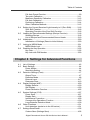
Manual Organization
1
Before Using
Outlines the package contents and identifies part
names and functions.
2
Installation and
Connection
Provides procedures for installing sensor amplifiers
and cables, as well as operating precautions.
3
Basic Operation
Explains basic instructions for operating and setting
the sensor amplifiers.
4
Settings for
Advanced
Functions
Describes settings for advanced functions of the
PS-N10 Series.
5
Specifications
Provides the specifications, circuit diagrams and
dimensions of the PS-N10 Series.
6
Appendix
Provides the troubleshooting instructions and initial
settings (default values).
1
2
3
4
5
6
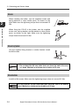
<Points for Using This Manual>
• When you "Forgot the operation methods" or "Want to find the operation procedures"
J Go to pages 3-2, 4-2
• When you "Want to try out the PS-N10"
J Go to Chapters 2 and 3
• When you "Want to fully utilize the various functions"
J Go to Chapters 3 and 4
• When you "Want to know the meanings of terms used"
J Go to Chapter 6 (Index)
• When you "Want to troubleshoot the PS-N10"
J Go to Chapter 6 (Troubleshooting)
- Digital Photoelectric Sensor PS-N10 Series User's Manual -
3
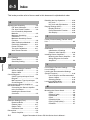
Table of Contents
Safety Precautions............................................................................... 1
General Precautions .......................................................................... 1
Precautions on Regulations and Standards ....................................... 2
Manual Organization ........................................................................... 3
Table of Contents ................................................................................. 4
Chapter 1 Before Using
1-1
1-2
Checking the Package Contents.......................................................... 1-2
Sensor Amplifier .............................................................................. 1-2
Sensor Head ................................................................................... 1-2
Part Names .......................................................................................... 1-4
Sensor Amplifier .............................................................................. 1-4
Chapter 2 Installation and Connection
2-1
2-2
2-3
Installing Sensor Amplifiers .................................................................. 2-2
Mounting the Sensor Amplifier ........................................................ 2-2
Wiring Diagrams for Sensor Amplifiers ........................................... 2-4
Connecting the Sensor Amplifier to the Sensor Head.......................... 2-5
Installing the Sensor Head Connector............................................. 2-5
Connecting the Sensor Amplifier to the Connector ......................... 2-6
Mounting the Sensor Head .................................................................. 2-7
PS-45 .............................................................................................. 2-7
PS-46/52(C)/56 ............................................................................... 2-7
PS-47(C)/49(C)/55(C) ..................................................................... 2-7
PS-48/58 ......................................................................................... 2-7
PS-05 .............................................................................................. 2-8
PS-201(C)/202 ................................................................................ 2-8
PS-205/206 ..................................................................................... 2-8
Chapter 3 Basic Operation
3-1
3-2
3-3
4
Quick Reference .................................................................................. 3-2
Switching Output.................................................................................. 3-4
Output Switch (L-on/D-on) .............................................................. 3-4
Adjusting the Sensitivity ....................................................................... 3-5
List of Sensitivity Adjustment Methods............................................ 3-5
Preset Function ............................................................................... 3-6
Work-Preset Function ..................................................................... 3-7
Maximum Sensitivity Preset Function ............................................. 3-8
- Digital Photoelectric Sensor PS-N10 Series User's Manual -
Table of Contents
3-4
3-5
3-6
3-7
3-8
Full Auto Preset Function ................................................................ 3-9
Two-point Calibration..................................................................... 3-11
Maximum Sensitivity Calibration ................................................... 3-12
Full Auto Calibration ...................................................................... 3-13
Positioning Calibration................................................................... 3-14
Other Calibration Methods ............................................................ 3-15
Setting the Current Received Light Intensity to 0 (Zero Shift)............ 3-16
Zero Shift Function........................................................................ 3-16
Operating Principle of the Zero Shift Function .............................. 3-16
Loading the Recommended Settings (Recipe Function) ................... 3-18
Selecting Recipe ........................................................................... 3-18
List of Recipes and Recommended Sensor Heads ...................... 3-19
Initialization ........................................................................................ 3-20
Initialization of Settings (Reset to Initial Values)............................ 3-20
Locking in MEGA Mode ..................................................................... 3-21
MEGA Mode Lock ......................................................................... 3-21
Disabling the Key Operation............................................................... 3-22
Key Lock........................................................................................ 3-22
Key Lock with PIN Number ........................................................... 3-23
Chapter 4 Settings for Advanced Functions
4-1
4-2
4-3
4-4
4-5
4-6
4-7
List of Settings ..................................................................................... 4-2
Basic Settings ...................................................................................... 4-4
Power Modes .................................................................................. 4-4
Sensitivity Setting............................................................................ 4-4
Detection Settings (Func) .................................................................... 4-7
Output Timer ................................................................................... 4-7
Detection Mode ............................................................................... 4-8
External Input................................................................................ 4-17
Parameter Save ............................................................................ 4-19
Display Settings (diSP) ...................................................................... 4-20
Display Reverse ............................................................................ 4-20
Sub Display ................................................................................... 4-20
Preset Saturation Function............................................................ 4-25
System Settings (SYS) ...................................................................... 4-27
Power Save ................................................................................... 4-27
Display Gain .................................................................................. 4-28
Interference Prevention ................................................................. 4-29
Common Key-Operations Function ............................................... 4-30
Long-Distance Detection Mode..................................................... 4-30
Other Functions ................................................................................. 4-31
Limit detection (exclusive to the NU series) .................................. 4-31
Settings Save/Recall .......................................................................... 4-32
Custom Save (Settings Save) ....................................................... 4-32
- Digital Photoelectric Sensor PS-N10 Series User's Manual -
5
Table of Contents
User Reset (Settings Recall) ......................................................... 4-33
Chapter 5 Specifications
5-1
5-2
5-3
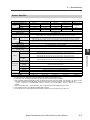
Specifications....................................................................................... 5-2
Sensor Head ................................................................................... 5-2
Sensor Amplifier .............................................................................. 5-3
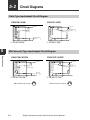
Circuit Diagrams .................................................................................. 5-4
Cable Type Input/output Circuit Diagram......................................... 5-4
M8 Connector Type Input/output Circuit Diagram ........................... 5-4
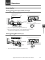
Dimensions .......................................................................................... 5-5
Sensor Amplifier .............................................................................. 5-5
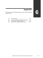
Chapter 6 Appendix
6-1
6-2
6-3
6-4
6-5
6
Troubleshooting.................................................................................... 6-2
Frequently Asked Questions ........................................................... 6-2
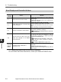
Error Displays and Corrective Actions............................................. 6-4
Factory Default Setting (Default Value) List .......................................... 6-5
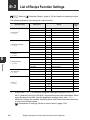
List of Recipe Function Settings .......................................................... 6-6
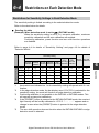
Restrictions on Each Detection Mode.................................................. 6-7
Restrictions for Sensitivity Settings in Each Detection Mode.......... 6-7
Index .................................................................................................... 6-8
- Digital Photoelectric Sensor PS-N10 Series User's Manual -
Before Using
This chapter outlines the package contents and identifies part
names and functions.
1-1
1-2
1
Checking the Package Contents ........................ 1-2
Part Names ........................................................ 1-4
- Digital Photoelectric Sensor PS-N10 Series User's Manual -
1-1
1-1
1
Checking the Package Contents
Before using the PS-N10 Series, make sure that the following equipment and
accessories are included in the package.
We have thoroughly inspected the package contents before shipment. However, in the
event of missing, defective or broken items, contact your nearest KEYENCE office.
Before Using
Sensor Amplifier
PS-N10 Series
Sensor amplifier x 1
Instruction manual x 1
Sensor head connector x 1
Sensor Head
PS-45
PS-46
Mounting bracket set
Receiver
Receiver
Mounting bracket
x1
Plate nut x 1
M3 x 12 screw x2
Nut x 2
Spring washer x 2
Flat washer x 2
M2 x 10 screw x 2
Transmitter
Transmitter
PS-47/PS-47C*1
PS-48
Mounting bracket x 1
Transmitter
Receiver
Receiver
Transmitter
PS-49/PS-49C*1
PS-05
Transmitter (T)
Transmitter
Receiver
Holder
1-2
Receiver (R)
Nut x 2
Spring washer x 2
Flat washer x 2
M3 x 14 screw x 2
For fixing
the head
Spring washer x 4
M3 x 10 screw x 4
For fixing
the holder
- Digital Photoelectric Sensor PS-N10 Series User's Manual -
1-1 Checking the Package Contents
PS-52/PS-52C*1
Transmitter (T)
PS-55/PS-55C*1
Receiver (R)
Transmitter (T)
1
Receiver (R)
Before Using
Nut x 4
Spring washer x 4
Flat washer x 4
M2 x 10 screw x 4
PS-58
PS-56
Transmitter (T)
Receiver (R)
Transmitter (T)
Receiver (R)
Mounting bracket x 2
Nut x 4
Spring washer x 4
Flat washer x 4
M2 x 10 screw x 4
PS-201/PS-201C*1
Transmitter (T)
Receiver (R)
PS-205
PS-202
Mounting bracket x 2
Transmitter (T)
Receiver (R)
Mounting bracket x 2
PS-206
Receiver
Transmitter
Receiver
Transmitter
*1 A sensor head connector is attached to the end of the cable for the sensor heads with model names
containing the suffix C.
- Digital Photoelectric Sensor PS-N10 Series User's Manual -
1-3
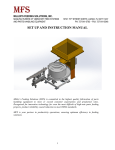
1-2
1
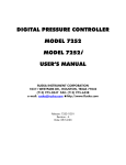
Part Names
Sensor Amplifier
Display/control unit
Before Using
Hold lock lever
Hook
Expansion connector*1
Expansion connector*1*2
Dust cover
M8 connector
(PS-N11C□/N12C□)
Connection cable
(PS-N11□/N12□)
w/o cable
(PS-N10)
*1 When shipped from the factory, the expansion cover is installed.
*2 This is not installed on the main unit (PS-N11N/N11P/N11CN/N11CP).
1-4
- Digital Photoelectric Sensor PS-N10 Series User's Manual -
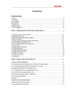
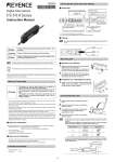
1-2 Part Names
Display/control unit
(1) (10)
(4)
(5)
1
(7)
Before Using
(3)
(2)
(8)
(9)
(6)
* Not available for the PS-N10.
Item
(1)
(2)
(3)
(4)
(5)
(6)
Description
Operation indicator Indicates the current output (detection) status.
Used when setting sensitivity, etc.
[SET] button
"Adjusting the Sensitivity" (page 3-5)
Setting value
Displays a setting value or advanced setting item in this
(Displayed in green) area of 7-segment green indicators.
Displays the current value (received light intensity), or a
Current value
selection from advanced settings, in this area of 7-seg(Displayed in red)
ment red indicators.
Manual button
Used to adjust the setting value or select an option.
Changes power modes.
SEL: Allows you to set a power mode using the "Changing Power Modes" function of basic setup.
Power select switch
M:
Fixes the power mode to "MEGA mode".
(7)
[PRESET] button
(8)
[MODE] button
(9)
DTM indicator
(10) PST indicator
"Locking in MEGA Mode" (page 3-21)
Used for presetting or setting values or parameters.
"Adjusting the Sensitivity" (page 3-5)
Used for toggling L-on/D-on, proceeding to advanced
settings, or confirming selections.
Lights when a DATUM mode is in effect.
"DATUM1 mode" (page 4-9)
"DATUM2 mode" (page 4-11)
Lights when preset value is set.
"Adjusting the Sensitivity" (page 3-5)
- Digital Photoelectric Sensor PS-N10 Series User's Manual -
1-5
1-2 Part Names
MEMO
1
Before Using
1-6
- Digital Photoelectric Sensor PS-N10 Series User's Manual -
Installation and Connection
This chapter provides procedures for installing sensor amplifiers and
cables, as well as operating precautions.
2-1
2-2
2-3
2
Installing Sensor Amplifiers................................. 2-2
Connecting the Sensor Amplifier to the Sensor Head..... 2-5
Mounting the Sensor Head................................. 2-7
- Digital Photoelectric Sensor PS-N10 Series User's Manual -
2-1
2-1
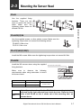
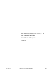
Installing Sensor Amplifiers
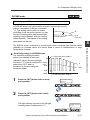
Mounting the Sensor Amplifier
Mounting on a DIN rail
2
1
Installation and Connection
2
Align the claw at the bottom of the main body
with the DIN rail, as shown on the right.
While pushing the main body in the direction
of the arrow (1), push down in the direction of
arrow (2).
(3)
(2)
(1)
To release the amplifier, raise the amplifier
body in the direction of arrow (3) while pushing in the direction of arrow (1).
Installation on a wall
Reference
This method applies only when using the main unit independently. If the
main unit is connected with an expansion unit(s), use the method of mounting on a DIN rail.
1
Mount the amplifier on the amplifier mounting bracket (OP-73880, sold separately),
using the same manner as "Mounting on a
DIN rail".
2
Secure the unit with two M3 screws as
shown in the illustration.
OP-73880
Connecting multiple amplifiers
Up to 16 expansion units can be connected to 1 main unit.
WARNING
2-2
Mount on DIN rail and install on metal surface when connecting
multiple amplifiers or mounting main units together.
- Digital Photoelectric Sensor PS-N10 Series User's Manual -
2-1 Installing Sensor Amplifiers
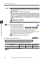
Point
1
Remove the protection covers from the main unit
and expansion unit(s).
2
Mount the main unit and expansion unit(s) on the
DIN rail.
(2)
(1)
3
Slide the main unit and expansion unit(s)
together.
Engage the 2 claws of the expansion unit with the
recesses on the main unit side until you hear/ feel
a click.
4
Attach the separately sold end units (OP-26751: a
set of 2 units) to the DIN rail in the same manner
as step (2).
5
Secure the amplifiers between the end units.
Tighten the screws at the top (2 screws × 2 units)
with a Phillips screwdriver to fix the end units.
OP-26751 (a set of 2 units)
- Digital Photoelectric Sensor PS-N10 Series User's Manual -
2-3
2
Installation and Connection
• Contact your nearest KEYENCE office when connecting a unit
other than the N-bus (KEYENCE’s wire-saving system) compatible
sensor amplifier, including PS-N10 Series, or the NU Series communication module.
• Turn the power off before connecting multiple expansion units.
• Do not touch the expansion connector with your bare hands.
• When using the PS-N10 Series as a main unit, use the products
within the expansion unit’s power voltage range if the power voltage range of the expansion unit is narrower than the PS-N10
Series.
2-1 Installing Sensor Amplifiers
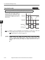
Wiring Diagrams for Sensor Amplifiers
Point
2
• Be sure to turn off the power before wiring.
• Insulate each input or output cable that will not be used.
Installation and Connection
Cable type (PS-N11
/N12
)
M8 connector type (PS-N11C
/N12C
)
Brown*
(1)*
10 to 30 VDC
10 to 30 VDC
(3)*
Blue*
(2)
Black
External input
Output
(4)
Pink*
External input
Output
* PS-N11CN/N11CP only
* PS-N11N/N11P only
OP-73864
(Cable length: 2 m)
OP-73865
(Cable length: 10 m)
Reference
2-4
Refer to
diagrams.
4
3
2
1
Pin and wire color table
Connected
pin No.
Wire color
1
2
3
4
Brown
White
Blue
Black
"Circuit Diagrams" (page 5-4) for the input/output circuit
- Digital Photoelectric Sensor PS-N10 Series User's Manual -
2-2
Connecting the Sensor Amplifier to the Sensor Head
Installing the Sensor Head Connector
1
2
Move the upper left part of the connector in the direction of the arrow
and then open the connector.
3
Fully insert the cables with the
shielded wires standing upright.
Next, bend the shielded wires along
the grooves in the direction of the
arrow.
2
10 mm or longer
Cable
core
Installation and Connection
Process the cable ends, as shown on
the right. The core wire conductors
are stripped so that they are exposed
at the time of shipment. Be sure to
process the cables without removing
the insulation from the cable ends.
Shielded wire
Red wire
White wire
4
Close the connector to crimp the
cables. Return the upper part of the
connector to its original position and
then lock it.
5
Using nippers, cut off the ends of
cables protruding from the connector.
NOTICE
Crimp the cables no more than three times. Excessively crimping
the cables may result in a bad connection.
- Digital Photoelectric Sensor PS-N10 Series User's Manual -
2-5
2-2 Connecting the Sensor Amplifier to the Sensor Head
Connecting the Sensor Amplifier to the Connector
1
Open the dust cover, and move the hold
lock lever down.
2
Lift the hook up, and insert the connector completely.
3
Lower the hook to the position
shown in the drawing, and pull
up the hold lock lever.
2
Installation and Connection
2-6
- Digital Photoelectric Sensor PS-N10 Series User's Manual -
2-3
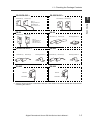
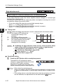
Mounting the Sensor Head
PS-45
Use the supplied fixing
brackets. There are two
ways to mount the sensor
head. Make sure the
tightening torque does not
exceed 0.6 Nm.
2
Installation and Connection
PS-46/52(C)/56
Use the supplied screws or other similar screws. Make sure the
tightening torque does not exceed the following values:
PS-46/56: 0.3 Nm or less
PS-52: 0.15 Nm or less
PS-47(C)/49(C)/55(C)
Install the M3 screws. Make sure the tightening torque does not exceed 0.6 Nm.
PS-48/58
Install the M3 screws when using the supplied
fixing brackets.
M3 setscrew (flat or dented head)
L
Make sure to observe the following
requirements when using setscrews to mount
the sensor head:
Model
L
PS-48
5 mm or longer
PS-58
7 mm or longer
Tightening torque
0.15 Nm or less
CAUTION
Note If you place the reflective PS-48 in the mounting hole, it is
affected by the light reflected from inside the hole. Place the front
side of the PS-48 so that it sticks out of the mounting hole, as
shown above.
- Digital Photoelectric Sensor PS-N10 Series User's Manual -
2-7
2-3 Mounting the Sensor Head
PS-05
2
When installing the holder, use the supplied screws and
spring washers or other similar parts, as shown on the
right. Make sure the tightening torque does not exceed 0.5
Nm.
Installation and Connection
When fixing the PS-05 to the holder, use the supplied
screw, nuts, spring washer, and flat washer or other similar
parts, as shown on the right. Make sure the tightening
torque does not exceed 0.5 Nm.
PS-201(C)/202
Use the supplied fixing bracket or similar bracket. Install
the M3 screws.
CAUTION
• Do not use setscrews to install the bracket.
• Do not bend the 20 mm cable that runs from the end of the sensor head. Maintain a minimum bend radius of 25 mm.
PS-205/206
Install the M4 screws. Make sure the tightening torque does not exceed 0.5 Nm.
CAUTION
2-8
Do not bend the 20 mm cable that runs from the end of the sensor
head. Maintain a minimum bend radius of 25 mm.
- Digital Photoelectric Sensor PS-N10 Series User's Manual -
Basic Operation
This chapter explains basic instructions for operating and setting the
sensor amplifier.
3-1
3-2
3-3
3-4
3-5
3-6
3-7
3-8
3
Quick Reference................................................. 3-2
Switching Output ................................................ 3-4
Adjusting the Sensitivity ............................................... 3-5
Setting the Current Received Light Intensity to 0 (Zero Shift) .. 3-16
Loading the Recommended Settings (Recipe Function) ... 3-18
Initialization....................................................... 3-20
Locking in MEGA Mode.................................... 3-21
Disabling the Key Operation ............................. 3-22
- Digital Photoelectric Sensor PS-N10 Series User's Manual -
3-1
3-1
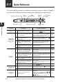
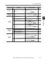
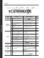
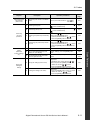
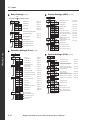
Quick Reference
The main setting operations are explained according to purpose. Refer to Chapter 4
for information on advanced function settings and explanations not given below.
Operation indicator
3
PST
indicator
Basic Operation
Changing the
output
Adjusting the
sensitivity and
integrating the
display to "100.0"
and ".0"
Adjusting the
sensitivity
Shifting the
received light
intensity to ."0"
Loading the
recommended settings
3-2
[MODE]
button
Description
[PRESET]
button
Power select
switch
Manual button
[SET] button
Purpose
DTM
indicator
Operation procedures
1. Press the [MODE] button.
Reference
page
1
Change the output. (L-on/D-on)
2
Set the current received light intensity
to "100.0". (Preset)
Reflective model: Press the [PRESET] button
when a workpiece is present. Thrubeam/Retroreflective model: Press the [PRESET] button
when no workpiece is present.
3-6
3
When preset is valid, register the
received light intensity ".0".
(Work-preset)
After step 2, press the [PRESET] button +
button in the state to be set as ".0".
3-7
4
Set the received light intensity slightly
higher than when the setting was
made, to "100.0". (Maximum sensitivity preset)
While the PST indicator is OFF, press and hold
the [PRESET] button. Reflective model: When
no workpiece is present. Thrubeam model:
When a workpiece is present.
3-8
5
Automatically register "100.0" and ".0"
when workpiece passes by. (Full Auto
preset)
Press and hold the [PRESET] button while the
PST indicator is OFF.
3-9
6
Cancel the various preset functions.
Press and hold the [PRESET] button.
3-6
7
Set the setting value at the midpoint
between the received light intensity
values when a workpiece is present
and absent. (2-point calibration)
1. Press the [SET] button once when a workpiece is present.
2. Press the [SET] button once when no workpiece is present.
3-11
8
Set the setting value slightly higher
than the received light intensity value
at which the setting was made. (Maximum sensitivity calibration)
Reflective model: Press and hold the [SET] button when no workpiece is present. Thrubeam
model: Press and hold the [SET] button when a
workpiece is present.
3-12
9
Set the setting value automatically
when a workpiece is passing through.
(Full auto calibration)
Press and hold the [SET] button while the workpiece passes through.
3-13
10
Set the setting value to the base point
where the workpiece is positioned.
(Positioning calibration)
1. Press the [SET] button once when no workpiece is present.
2. Press and hold the [SET] button at the positioning point.
3-14
11
Finely adjust the setting value directly.
Press the
1-5
12
Set the current display to ."0". (Zero
shift)
Press the [PRESET] button +
the PST indicator is OFF.
13
Cancel the zero shift function.
Press and hold the [PRESET] button.
3-16
Load the recommended settings.
(Recipe function)
1. Press and hold the [SET] button and [PRESET] button.
2. Display the LoAd screen with the
(
)
button, and press the [MODE] button.
3. Select the recipe such as r-1 FALL with the
(
) button.
4. Press the [MODE] button to execute.
3-18
14
2. Switch with the
(
(
) button.
) button.
- Digital Photoelectric Sensor PS-N10 Series User's Manual -
button when
3-4
3-16
3-1 Quick Reference
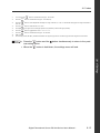
Purpose
Initializing the settings
Switching to the
maximum received
light intensity
power mode
Others
(Advanced
function settings,
etc.)
Reference
page
Operation procedures
15
Initializing (Restore to factory default
settings)
1. Press and hold the [SET] button and [PRESET] button.
2. Press the [MODE] button while on the rSt
screen.
3. Select init with the
(
) button.
4. Press the [MODE] button to execute.
3-20
16
Adjust the power mode to the MEGA
mode.
Set the power select switch to
3-21
17
Activating the key lock
18
Deactivating the key lock
.
Press and hold the [MODE] button and the
(
) button simultaneously.
Press and hold the [MODE] button and the
(
) button simultaneously.
3-22
19
Activating the password-protected key
lock
1. Press the
(
) button10 times while
holding down the [MODE] button.
2. Input the password with the
(
) button.
3. Press the [MODE] button to execute.
20
Deactivating the password-protected
key lock
1. Press the
(
) button 10 times while
holding down the [MODE] button.
2. Input the password with the
(
) button.
3. Press the [MODE] button to deactivate the
key lock.
3-23
21
Setting the advanced functions
Press and hold the [MODE] button.
4-1
22
Switching the display to extended display or received light intensity hold
display, etc. (sub-display)
After setting the sub-display with the advanced
function settings, press the [MODE] button
twice.
4-20
23
Resetting the following values
* Received light intensity hold value
* Excess gain hold value
Press and hold the [MODE] button and [SET]
button.
4-22
4-24
Saving the settings (custom save)
1. Press and hold the [SET] button and [PRESET] button.
2. Display the SAvE screen with the
(
)
button, and press the [MODE] button.
3. Select yES with the
(
) button.
4. Press the [MODE] button to execute.
4-32
Loading the settings (user reset)
1. Press and hold the [SET] button and [PRESET] button.
2. Press the [MODE] button on the rSt screen.
3. Select USEr with the
(
) button.
4. Press the [MODE] button to execute.
4-33
24
Saving and
loading the
settings
25
- Digital Photoelectric Sensor PS-N10 Series User's Manual -
3
3-22
3-23
3-3
Basic Operation
Preventing
incorrect
operations
Description
3-2
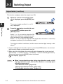
Switching Output
Output Switch (L-on/D-on)
This function configures when the output turns ON.
1
3
When the current received light intensity is displayed, press the [MODE] button.
The current output condition (L-on or Don) is displayed.*1
Basic Operation
2
Press the
button to switch the output condition, and then press the
[MODE] button.
Select "D-on" if you want to output the ON
signal when the beam is blocked (a workpiece is present.) for a thrubeam model.
Select "L-on" if you want to output the ON signal when the beam is received (a
workpiece is present.) for the reflective model.
The output condition is switched, and the current received light intensity is displayed.*2
*1 If you do nothing for 3 seconds or more or press the [MODE] button, the received
light intensity display is automatically restored.
*2 When using the sub-display, the screen will switch between the current received
light intensity J L-on/D-on screen J sub-display J current received light intensity
and so forth each time the [MODE] button is pressed.
"Sub Display" (page 4-20)
Point
3-4
• When in area detection mode, rising edge detection mode, or falling edge detection mode, this function works as a normally-open/
normally-closed switch.
"Area detection mode" (page 4-14)
"Rising edge detection mode" (page 4-16)
"Falling edge detection mode" (page 4-16)
- Digital Photoelectric Sensor PS-N10 Series User's Manual -
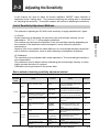
3-3
Adjusting the Sensitivity
In this manual, the value at which the sensor amplifier's ON/OFF output switches is
expressed as the "setting value". The process of adjusting the setting value is expressed
as "adjusting the sensitivity". This section explains the method of adjusting the sensitivity.
List of Sensitivity Adjustment Methods
The methods of adjusting the PS-N10 series sensitivity is largely classified into 2 types.
(2) Calibration
The sensitivity can be adjusted with simple operations. The received light intensity is
not compensated.
This method is used to adjust without calibrating the received light intensity, or when
highly accurate detection is required.
Calibration can be performed in the preset state.
Basic method of selecting sensitivity adjustment method
Sensitivity
adjustment
method
Usage
Details
Reference
Preset
The sensitivity is adjusted just by
pressing the [PRESET] button when
a workpiece is absent.
3-6
Using a reflective model
Maximum sensitivity preset
The sensitivity is adjusted just by
pressing and holding the [PRESET]
button when a workpiece is absent.
3-8
"100.0" and ".0" cannot be set
regardless of whether a workpiece is present or absent.
Work-preset
The states at which to display
"100.0" and ".0" can be set randomly.
3-7
The moving workpiece moves
quickly
Full auto preset
The sensitivity can be calibrated
using a workpiece which moves at
high speed.
3-9
Using a thrubeam reflective
model
Two-point
calibration
The setting can be established just
by pressing the [SET] button once
when a workpiece is present and
absent.
3-11
The moving workpiece moves
quickly
Full auto
calibration
The sensitivity can be calibrated
using a workpiece which moves at
high speed.
3-9
Using in an easily contaminated environment
Maximum sensitivity calibration
This setting prevents malfunctions
even when using in an easily contaminated environment.
3-8
Using with positioning
Positioning calibration
A setting suitable for positioning can
be made.
3-14
Using with highly accurate
detection
Percentage calibration
This is useful for calibrating from an
external device, such as a PLC.
3-15
Using a thrubeam model
Function
Basic
Preset
At times
like this
Basic
Calibration
At times
like this
- Digital Photoelectric Sensor PS-N10 Series User's Manual -
3-5
3
Basic Operation
(1) Preset
At the same time as adjusting the sensitivity, the received light intensity can be
calibrated to "100.0" or ".0" using simple operations.
This method can decrease the variation of the received light intensity depending on
the contents of the detection and the workpiece, and is useful for predictive
maintenance.
However, this is not suitable for when difference in received light intensity varies little
with or without a workpiece, such as when detecting a transparent workpiece.
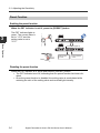
3-3 Adjusting the Sensitivity
Preset Function
Enabling the preset function
When the PST indicator is not lit, press the [PRESET] button
3
The PST indicator lights in
green. The current value is
set to "100.0" and the
setting value is set to
"50.0".
Basic Operation
Green PST lights up
Workpiece
Setting value
is "50.0"
Current value is
"100.0"
Disabling the preset function
When the PST indicator is lit, press and hold the [PRESET] button.
• The PST indicator turns off, indicating that the preset function has been disabled.
• Once the preset function is disabled, the setting value is recalculated while
retaining the ratio of the setting value and received light intensity.
3-6
- Digital Photoelectric Sensor PS-N10 Series User's Manual -
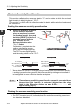
3-3 Adjusting the Sensitivity
Work-Preset Function
This function calibrates the current value to ".0". After the preset function has been
executed with "100.0" displayed, and then executing this function with ".0" displayed, 2
random set points can be calibrated to "100.0" and ".0".
Enabling the work-preset function
Impotant
The work-preset function can be used with the preset function (when
preset is enabled).
The received light intensity
at that point is set to ".0".
The value set to "100.0"
using the preset function
does not change.
button
100.0
3.0
.0
[PRESET]+
Green PST
lights up
Current value is ".0"
Reference
Even if the received light intensity is low during preset and is high during
work-preset, the value is set to "100.0" during preset and ".0" during workpreset. When the actual received light intensity increases, the display will
approach ".0". (The preset saturation level is decreased with respect to
"100.0".)
Disabling the work-preset function
When the PST indicator is lit, press and hold the [PRESET] button.
• The PST indicator turns off, indicating that the work-preset function has been
disabled.
- Digital Photoelectric Sensor PS-N10 Series User's Manual -
3-7
Basic Operation
While the preset function is enabled, press the [PRESET] button and
simultaneously.
3
3-3 Adjusting the Sensitivity
Maximum Sensitivity Preset Function
This function calibrates the reference state to ".0" and the state at which the received
light intensity is slightly higher as "100.0".
This function is useful with the reflective model to detect while using the background
as a reference.
Enabling the maximum sensitivity preset function
3
1
Basic Operation
When no workpiece is present
for the reflective model, or
when a workpiece is present
for thrubeam model, press and
hold the [PRESET] button for 3
seconds or more while the
PST indicator is OFF.
Release the button when
"Auto" flashes.
Calibration is complete after the
setting value flashes momentarily, and then stops (lights up).
The PST indicator lights in green,
and the setting value is set to "50.0".
Thrubeam Model
Reflective Model
Received light intensity
Received light intensity
No workpiece
With workpiece*
"100.0" Saturation point
"50.0" Setting value
".0" With workpiece
Saturation point
Setting value
No workpiece*
1
1
"100.0"
"50.0"
".0"
* Where detection occurs on a target having a background, the maximum sensitivity setting ignores the background. Maximum sensitivity setting is not available if
the background is more reflective than the workpiece.
Point
• The maximum sensitivity preset function cannot be executed when
the received light intensity is saturated (higher than the value
listed in the Extension display on page 4-28). ("---- ----" will
appear during step 1.)
Disabling the maximum sensitivity preset function
When the PST indicator is lit, press and hold the [PRESET] button.
• The PST indicator turns off, indicating that the maximum sensitivity preset function has been disabled.
3-8
- Digital Photoelectric Sensor PS-N10 Series User's Manual -
3-3 Adjusting the Sensitivity
Full Auto Preset Function
This function automatically judges 2 states (workpiece presence/absence, etc.), and
calibrates the current value to "100.0" and ".0".
This is useful when the detector is moving at high speed, etc.
Enabling the full auto preset function
When the PST indicator is OFF, continue pressing the [PRESET] button until "Auto" flashes
while the workpiece passes through.
2
After the workpiece has completely
passed through, release the [PRESET] button.
Calibration is complete after the setting
value flashes momentarily, and then
stops (lights up).
The PST indicator lights in green, and
the setting value is set to "50.0".
3
Basic Operation
1
MAX
".0"
Received
light intensity
"100.0"
"50.0"
Setting
value
MIN
Time
1
The area near the maximum value
of the received light intensity while
the [PRESET] button is pressed is
set as "", and the area near
the minimum value is set as "".
2
Point
The full auto preset function cannot be executed when the received
light intensity is saturated (higher than the value listed in Extension
display on page 4-28). ("---- ----" will appear during step 2.)
- Digital Photoelectric Sensor PS-N10 Series User's Manual -
3-9
3-3 Adjusting the Sensitivity
Disabling the full auto preset function
When the PST indicator is lit, press and hold the [PRESET] button.
• The PST indicator turns off, indicating that the full auto preset function has been
disabled.
Point
3
Each preset function cannot be used when the following functions are
set. Disable the function or change the setting before executing the
preset function.
• Zero shift function -> "Zero Shift Function" (page 3-16)
• Zero shift calibration ->
"Adjusting the Sensitivity" (page 3-5)
Basic Operation
• Zero shift input ->
"External Input" (page 4-17)
• DATUM 1/2 mode -> "Restrictions for Sensitivity Settings in Each
Detection Mode" (page 6-7)
• Rising/falling edge detection mode" -> "Restrictions for Sensitivity
Settings in Each Detection Mode" (page 6-7)
• The preset function is not suited for transparent workpieces such
as thrubeam models and other cases of detection with low light
intensity differences.
• After changing any of the following settings, disable each preset
function once and then execute again.
"Power Modes" (page 4-4)
"Preset Saturation Function" (page 4-25)
"Display Gain" (page 4-28)
• If the received light intensity raw value is 50 or less (200 or less
when the light intensity is set to FuLL), the display will be "100.0" or
less when the preset function is executed.
Reference
• If the [PRESET] button is pressed when the preset function is enabled
(PST indicator is lit), the current received light intensity changes to
"100.0" and the setting value does not change.
• Expansion units can be preset with operations from the main unit.
"Common Key-Operations Function" (page 4-30)
• Periodic presetting is possible with signals input from an external source.
"External Input" (page 4-17)
• With the preset function, a process is carried out to ignore minute
received light intensity changes which do not affect the detection. The
change amount to be ignored can be adjusted randomly.
"Preset Saturation Function" (page 4-25)
If the sub-display is changed to "Extension", the original received light
intensity can be confirmed even when using the preset function.
Extension ->
3-10
"Sub Display" (page 4-20)
- Digital Photoelectric Sensor PS-N10 Series User's Manual -
3-3 Adjusting the Sensitivity
Two-point Calibration
Two-point calibration is the most basic method of sensitivity setting.
The setting value can be established by simply pressing the [SET] button once each
when a workpiece is present. and when it is absent.
1
3
Basic Operation
2
Press the [SET] button once
when no workpiece is
present.
Press the [SET] button once
when a workpiece is present.
Calibration is complete after the
setting value flashes momentarily, and then stops (lights up).
Press the
button to adjust
the setting value.
Reference
Step 1 or step 2 may be performed first.
Received
light intensity
1
2
Setting
value
The setting value is set to the middle
of the values at which the [SET] button
was pressed first and pressed second.
Time
* If the difference between the 2 conditions is too small, "- - - -" flashes
after calibration is complete.
However, the setting value will still established.
- Digital Photoelectric Sensor PS-N10 Series User's Manual -
3-11
3-3 Adjusting the Sensitivity
Maximum Sensitivity Calibration
This sensitivity setting method is useful if the received light intensity is reduced by
dust or dirt.
The setting value is calibrated to be slightly more than the light intensity received when
it is determined.
3
1
Basic Operation
When a workpiece is absent for the
reflective model, or when a workpiece is present for the thrubeam
model/retro-reflective model, press
and hold the [SET] button for 3 seconds or more.
Release the button when "SEt"
flashes.
Calibration is complete after the setting
value flashes momentarily, and then
stops (lights up).
Press the
button to adjust the setting value.
Reflective Model
Thrubeam Model
Received light intensity
Received light intensity
No workpiece
With workpiece*
Setting value
With workpiece
Setting value
No workpiece*
1
1
* Where detection occurs on a target having a background, the maximum sensitivity setting ignores the background. Maximum sensitivity setting is not available if the background is more reflective than the workpiece.
3-12
- Digital Photoelectric Sensor PS-N10 Series User's Manual -
3-3 Adjusting the Sensitivity
Full Auto Calibration
This method automatically sets sensitivity using a moving workpiece.
Sensitivity can be easily set by passing a workpiece without shutting down operating
equipment.
1
3
Basic Operation
2
While the workpiece passes through,
press and hold the [SET] button until
"SEt" flashes.
After the workpiece has completely
passed through, release the [SET] button.
Calibration is complete after the setting
value flashes momentarily, and then
stops (lights up).
Reference
• When performing two-point calibration on channel 2 of the 2-output type,
set the channel switch to "2".
Received
light intensity
MAX
Setting
value
MIN
Time
1
2
The setting value is determined
as the middle value between the
maximum and minimum light
intensity received values
obtained while holding down the
[SET] button.
- Digital Photoelectric Sensor PS-N10 Series User's Manual -
3-13
3-3 Adjusting the Sensitivity
Positioning Calibration
This method is used when you want to position a workpiece.
1
Press the [SET] button
once when no workpiece is
present.
2
Position a workpiece such
that its edge aligns with the
center of the projecting
Workpiece
beam. Then, press and hold
the [SET] button for 3 seconds or more. Release the
button when "SEt" flashes.
The setting value is determined as the value of light
intensity received when the
workpiece comes into position. Calibration is complete
after the setting value flashes
momentarily, and then stops (lights up).
Press the
button to adjust the setting value.
3
Basic Operation
Received
light intensity
Setting
value
1
3-14
2
Time
- Digital Photoelectric Sensor PS-N10 Series User's Manual -
3-3 Adjusting the Sensitivity
Other Calibration Methods
Percentage calibration
A setting value is established with a percentage in respect to the current received light
intensity. When used together with external calibration input, percentage calibration
can be performed from an external device, such as a PLC, allowing highly accurate
detection of transparent workpieces and small workpieces, etc.
Refer to
3
"Sensitivity Setting" (page 4-4) for details.
Zero shift calibration
Refer to
"Sensitivity Setting" (page 4-4) for details.
- Digital Photoelectric Sensor PS-N10 Series User's Manual -
3-15
Basic Operation
This sensitivity setting performs the zero shift function and basic calibration (two-point
calibration / maximum sensitivity calibration / full auto calibration) simultaneously.
The lower of the received light intensity values specified at the time of sensitivity
setting will automatically be set to 0.
3-4
Setting the Current Received Light Intensity to 0 (Zero Shift)
Zero Shift Function
This function adjusts the current received light intensity display to "0". It is primarily
used with reflective sensor heads. If the received light intensity cannot be set to "0"
when a reflective model is installed, this function can be used to set the received light
intensity to "0" with no workpiece present. This makes the difference in received light
intensity easier to distinguish.
3
Enabling the zero shift function
Basic Operation
1
When the PST indicator is off, press
the [PRESET] button and
button
simultaneously.
The PST indicator lights in green, and the
received light intensity changes to "0".
Green PST lights up
Current value is "0"
Disabling the zero shift function
1
When the PST indicator is on, press and hold the [PRESET] button.
The PST indicator turns off, indicating that the zero shift function has been disabled.
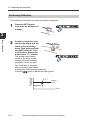
Operating Principle of the Zero Shift Function
< For reflective models >
Received light intensity
Received light intensity
650
450
450
400
250
200
300
200
0
Without workpiece
100
(Background is detected)
0
In applications for distinguishing colors or
for detecting objects on a background,
the received light intensity will not be "0"
even when no workpiece is present.
3-16
Applying zero shift input to the lower
level of received light intensity (with
no workpiece present) enhances
the detection display visibility.
- Digital Photoelectric Sensor PS-N10 Series User's Manual -
3-4 Setting the Current Received Light Intensity to 0 (Zero Shift)
Point
Reference
The zero shift function cannot be used in combination with the preset
function. To use the zero shift function, make sure that the preset
function is disabled (the PST indicator is not lit).
Zero shift of the expansion unit can be set from the main unit.
"Common Key-Operations Function" (page 4-30)
3
Basic Operation
- Digital Photoelectric Sensor PS-N10 Series User's Manual -
3-17
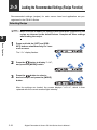
3-5
Loading the Recommended Settings (Recipe Function)
Recommended settings (recipes) for each sensor head and application are preregistered in the PS-N10 Series.
Selecting Recipe
Point
3
Basic Operation
1
When a recipe is loaded, all settings other than those registered in the
recipe are returned to the default values. Complete all other settings
after loading the recipe.
Press and hold the [SET] and [PRESET] buttons simultaneously for 3 seconds or more.
The "rSt" display flashes.
2
Press the
button to display "LoAd",
and press the [MODE] button.
3
Press the
button to select a
desired recipe, and press the [MODE]
button.
After the settings are loaded, the screen displays "LoAd oK", which is then
replaced with the current received light intensity.
3-18
- Digital Photoelectric Sensor PS-N10 Series User's Manual -
3-5 Loading the Recommended Settings (Recipe Function)
List of Recipes and Recommended Sensor Heads
Recipe
Fall
(r-1 FALL)
Zero-Shift
(r-3 0SEt)
MEGA
(r-4 MEGA)
AREA
(r-5 ArEA)
0 DATUM
(r-6 0dtM)
Reference
Description
To detect a falling workpiece.
The falling edge of the received light intensity is
Thrubeam model detected, and output as one-shot.
The received light intensity hold value can be confirmed by pressing the [MODE] button twice.
To use the external input and periodically compenThrubeam model sate for the reduction in received light intensity due
to contamination on sensor head face.
To use the external input and "0" the light intensity
received without a workpiece present.
Reflective model The background received light intensity is set as 0
even when calibrating with the buttons on the display.
(Zero Shift calibration)
To 0 the lower of level received light intensity values
in order to display higher values of received light
Reflective model intensity.
The display can be extended up to 5 digits by pressing the [MODE] button twice.
This is recommended when outputting within a specific received light intensity range. When the [SET]
button is pressed once at the reference received light
Reflective model
intensity, the upper/lower setting value limits will be
set at μ10% from the reference received light intensity.
This is recommended when detecting a transparent
workpiece. The received light intensity at the state
with no workpiece is set as ".0", and the displayed
value is increased as the amount of light blocked by
Thrubeam model
the workpiece increases.
When the [SET] button is pressed or when calibrated
with external inputs, the received light intensity -5%
at that point is set as the setting value.
Refer to "List of Recipe Function Settings" (page 6-6) for the details on the
items set with recipe loading.
- Digital Photoelectric Sensor PS-N10 Series User's Manual -
3-19
3
Basic Operation
Percentage
calibration
(r-2 SEtP)
Recommended
head
3-6
Initialization
Initialization of Settings (Reset to Initial Values)
The sensor amplifier can be reset to the factory default settings.
1
Press and hold the [SET] and [PRESET] buttons simultaneously for 3 seconds or more.
The "rSt" display flashes.
3
Basic Operation
2
Press the [MODE] button.
3
Press the
4
Press the [MODE] button.
button to display "init".
After the settings are initialized, the screen
displays "oK", which is then replaced with
the current received light intensity.
Reference
3-20
Refer to
"Factory Default Setting (Default Value) List" on page 6-5.
- Digital Photoelectric Sensor PS-N10 Series User's Manual -
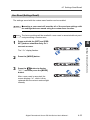
3-7
Locking in MEGA Mode
MEGA Mode Lock
The sensor amplifier can be locked in MEGA mode, such that it always operates in
MEGA mode regardless of the power mode selected in the basic setup.
"Power Modes" (page 4-4)
1
Slide the power select switch to the
"M" side.
3
Reference
• When the amplifier is locked in MEGA mode, the power mode may not be
changed in the basic setup, as indicated by the flashing of "Loc".
"Power Modes" (page 4-4)
• Likewise, when the amplifier is in the key locked state, the power mode
may not be changed, as indicated by the flashing of "Loc".
"Key Lock" (page 3-22)
- Digital Photoelectric Sensor PS-N10 Series User's Manual -
3-21
Basic Operation
Sliding the power select switch back to the
"SEL" side restores the power mode that
was set before sliding the power select
switch to MEGA mode.
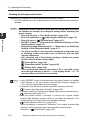
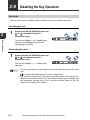
3-8
Disabling the Key Operation
Key Lock
The key lock function disables all key operation to prevent unauthorized use.
Activating key lock
3
1
Press and hold the [MODE] button and
(or
) simultaneously for 3
seconds or more.
Basic Operation
The screen displays "Loc", disabling key
operation and displaying the current
received light intensity.
Deactivating key lock
1
Press and hold the [MODE] button and
(or
) simultaneously for 3
seconds or more.
The screen displays "unL", enabling key
operation.
Reference
• The key operations on the expansion unit can be locked from the main
unit.
"Common Key-Operations Function" (page 4-30)
• By using the network unit NU series, key locks which could only be disabled via the network can be set. This function allows you to change only
the necessary settings with a PLC and touch panel. Refer to the NU
Series User's Manual for details.
3-22
- Digital Photoelectric Sensor PS-N10 Series User's Manual -
3-8 Disabling the Key Operation
Key Lock with PIN Number
A PIN number can be set when activating key lock. Only users knowing the PIN
number can operate the unit.
Activating key lock with a PIN number
1
Press
(or
) 10 times while holding
down the [MODE] button.
3
2
Press the
button to set a desired
number (up to 4 digits).
3
Press the [MODE] button.
Basic Operation
The screen displays "Loc 0".
The screen displays "Loc", disabling key
operation and displaying the current
received light intensity.
Deactivating key lock with a PIN number
1
Hold down the [MODE] button while
pressing
(or
) 10 times.
The screen displays "Loc 0".
2
Press the
button to specify the
PIN number, and then press the
[MODE] button.
The screen displays "unL", enabling key
operation.
Point
If the PIN number is lost, contact your nearest KEYENCE office.
- Digital Photoelectric Sensor PS-N10 Series User's Manual -
3-23
3-8 Disabling the Key Operation
3
Basic Operation
3-24
- Digital Photoelectric Sensor PS-N10 Series User's Manual -
Settings for Advanced Functions
This chapter describes settings for advanced functions of the PSN10 Series.
4-1
4-2
4-3
4-4
4-5
4-6
4-7
4
List of Settings.................................................... 4-2
Basic Settings..................................................... 4-4
Detection Settings (Func)................................... 4-7
Display Settings (diSP)..................................... 4-20
System Settings (SYS)..................................... 4-27
Other Functions................................................ 4-31
Settings Save/Recall......................................... 4-32
- Digital Photoelectric Sensor PS-N10 Series User's Manual -
4-1
4-1
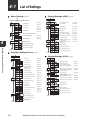
List of Settings
Basic Settings…(page 4-4)
Display Settings (diSP)…(page 4-20)
MODE
Press and hold
for 3 seconds or more
Normal display method
…(page 4-20)
Reverse display
…(page 4-20)
…(page 4-4)
Sub-display off
…(page 4-20)
ULTRA mode
…(page 4-4)
Extension display
…(page 4-21)
MEGA mode
…(page 4-4)
Bar display
…(page 4-21)
…(page 4-4)
Excess gain (%) display
…(page 4-22)
Light intensity hold display *6
…(page 4-22)
…(page 4-4)
TURBO mode
…(page 4-4)
SUPER mode
Normal sensitivity setting method
Percentage Calibration*1
…(page 4-4)
Excess gain hold (%) display *6 …(page 4-24)
…(page 4-5)
Zero-shift calibration
L-on / D-on display
…(page 4-24)
Enable the saturation of the
Preset function *7
Disable the saturation of the
Preset function
…(page 4-25)
…(page 4-6)
4
Settings complete
Go to detection setup mode
…(page 4-25)
Settings complete
Go to display setup mode
Go to system setup mode
Settings for Advanced Functions
Go to system setup mode
Go to detection setup mode
Return to normal display
Return to display setup mode
Detection Settings (Func)…(page 4-7)
Return to normal display
System Settings (SYS)…(page 4-27)
Timer OFF
…(page 4-7)
Off-delay timer *2
…(page 4-7)
On-delay timer *2
…(page 4-7)
2
…(page 4-7)
One-shot timer *
Normal (light intensity)
detection mode
…(page 4-27)
Enable Eco Function
…(page 4-27)
Reduce power consumption
(response time 4 times slower)
…(page 4-27)
…(page 4-28)
DATUM1 mode *
…(page 4-9)
Standard current value display
DATUM2 mode *3
…(page 4-11)
Maximum current value display
(4 times hysteresis)
…(page 4-28)
Area detection mode
…(page 4-14)
Normal operation
…(page 4-29)
Rising Edge Detection Mode
…(page 4-16)
Falling Edge Detection Mode
…(page 4-16)
External input off
…(page 4-17)
External calibration input
…(page 4-17)
Preset input
…(page 4-17)
Zero shift input
…(page 4-17)
Reset input
…(page 4-17)
Light transmission OFF input
…(page 4-17)
Pause function *4
…(page 4-18)
Sleep function
…(page 4-19)
3
*5
…(page 4-8)
Disable Eco Function
Twice the number of
interference-prevention units as STD
(response time 2 times slower)
…(page 4-29)
*8
Disable common key operations
…(page 4-30)
Enable common key operations
…(page 4-30)
Disable long mode
*9
Enable long mode
Settings complete
Go to detection setup mode
Go to display setup mode
Return to system setup mode
MODE
Settings complete
Go to display setup mode
Return to normal display
Go to system setup mode
Return to detection
setup mode
Return to normal display
4-2
- Digital Photoelectric Sensor PS-N10 Series User's Manual -
4-1 List of Settings
*1
You can press the
MODE
MODE
button to set between the range of -99P and 99P.
*2
Press the
button to set between the range of 1 and 9999 (ms).
*3
Press the
button to set the adjustment sensitivity to a range of between LEu1 and LEu3 and set the warning level to a range of
between 0P and 100P.
*4
*5
Press the
button to switch between oFF/on/KEEP.
This display does not appear on the cable-type expansion unit (PS-N12
) and the 0-line type (PS-N10).
*6
Press the
*7
*8
*9
Press the
button to set between the range of 100P and 200P.
Main unit only.
The PS-47(C), PS-48, PS-49(C), PS-58 and PS-206 do not support long mode. Do not select long mode when using these sensor heads.
MODE
MODE
MODE
button to toggle between Std/P~P_/b~b_/P_b~/P~b_.
MODE
Reference
MODE
• Press the
button and the
previous setting option.
• When the
MODE
button simultaneously to return to the
4
button is held down, the settings menu will end.
Settings for Advanced Functions
- Digital Photoelectric Sensor PS-N10 Series User's Manual -
4-3
4-2
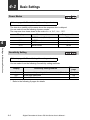
Basic Settings
Power Modes
Refer to page 4-2 "Basic Settings" for setting methods.
The detection stability will increase when the response time is delayed.
You can select from the following 4 power modes.
The response time slows down in the order of turb, Supr, ULtr, MEGA.
Display
Response time
TURBO mode (Default)
SUPER mode
ULTRA mode
MEGA mode
turb
SuPr
ULtr
MEGA
4
Power mode name
500 øs
1 ms
4 ms
16 ms
Settings for Advanced Functions
Sensitivity Setting
Refer to page 4-2 "Basic Settings" for setting methods.
You can select from the following 3 sensitivity setting methods.
Display
Std
SEtP
0SEt
Sensitivity setting method
Normal sensitivity setting (without correction) (Default)
Percentage calibration
Zero shift calibration
* Refer to the following 2 pages for details.
4-4
- Digital Photoelectric Sensor PS-N10 Series User's Manual -
Reference
page
3-5 to 3-14
4-5
4-6
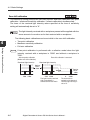
4-2 Basic Settings
Percentage calibration
The setting value can be specified as a
percentage in respect to the current received
light intensity.
Setting example When the percentage calibration
target value is set to "-10%".
Received light intensity
The percentage calibration target value can be
1000
set in the range of "-99P" (-99%) to 99P (99%)
900
Default: -10P (-10%)
Reference
Sensitivity setting
1
4
Reference
• If the external input setting is set to "SEt" (external calibration input), periodic percentage calibration is possible from external devices, enabling
stable detection even on workpieces having small sensitivity differences.
"External Input" (page 4-17)
• If the detection mode is set to "ArEA (area detection mode)", Hi and Lo
are set simultaneously according to the received light intensity.
(Example)
If the percentage calibration is set
to 10P (10%) when the reference
received light intensity is "100",
the Hi and Lo setting values will be
set as follows.
Hi setting value: 110
Lo setting value: 90
Hi
110
Received
light intensity
100
Lo
- Digital Photoelectric Sensor PS-N10 Series User's Manual -
90
4-5
Settings for Advanced Functions
In the desired reference state, press
the [SET] button.
Calibration is complete after the setting
value flashes momentarily, and then
stops (lights up).
4-2 Basic Settings
Zero shift calibration
This sensitivity setting performs the zero shift function and basic calibration (two-point
calibration / maximum sensitivity calibration / full auto calibration) simultaneously.
The lower of the received light intensity values specified at the time of sensitivity
setting will automatically be set to "0".
Reference
The light intensity received with a workpiece present will be applied with the
same amount of correction as for that received with no workpiece.
The following basic calibrations can be set while in the zero shift calibration.
4
• Two-point calibration
• Maximum sensitivity calibration
• Full auto calibration
Settings for Advanced Functions
Setting example If two-point calibration is performed with a reflective model when the light
intensity received with a workpiece is "2500" and without a workpiece is
"500":
After two point calibration
(Before zero shift calibration)
Received light intensity
Zero shift calibration is executed
Received light intensity
Setting
value
1500
500 2500
4-6
Setting
value
1000
500 2500
The light intensity received
with no workpiece is
subtracted from the whole.
0
2000
The state with no
workpiece (the lowest of
received light intensity) is
set to "0".
- Digital Photoelectric Sensor PS-N10 Series User's Manual -
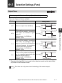
4-3
Detection Settings (Func)
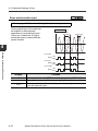
Output Timer
Refer to page 4-2 "Detection Settings (Func)" for setting methods.
There are 3 types of timers available.
Display
Function
Timing chart*
Without workpiece With workpiece Without workpiece
toFF
on-d
Shot
ON
Control output
OFF
Off-delay timer
Without workpiece With workpiece Without workpiece
Turns off the output at a specified
time after the detection signal Control output ON
OFF
goes off.
Setting range: 1 to 9999 ms
Timer-set period
Default: 10 ms
On-delay timer
Turns on the output at a specified
Without workpiece With workpiece Without workpiece
time after the detection signal
ON
goes on. Useful if the ON duration
Control output
is limited because the workpiece
OFF
is shaky such as by vibration.
Timer-set period
Setting range: 1 to 9999 ms
Default: 10 ms
One-shot timer
Without workpiece With workpiece Without workpiece
Turns on the output and keeps it
on for a specified period after the Control output ON
OFF
detection signal goes on.
Setting range: 1 to 9999 ms
Timer-set period
Default: 10 ms
* Example of the light-ON (L-on) mode for the reflective model and the dark-ON (don) mode for the thrubeam model.
Reference
The timer can only control on/off switching of the sensor output.
- Digital Photoelectric Sensor PS-N10 Series User's Manual -
4-7
4
Settings for Advanced Functions
oFFd
Uses no output timer. (Default)
4-3 Detection Settings (Func)
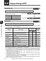
Detection Mode
Refer to page 4-2 "Detection Settings (Func)" for setting methods.
The table below lists the detection modes that can be selected.
Display
4
Detection mode
Settings for Advanced Functions
Std
Normal detection
dtM1
DATUM1 mode*
dtM2
DATUM2 mode*
ArEA
Area detection mode
_|~d
~L_d
Rising edge detection
mode
Falling edge detection
mode
Function
Normal detection mode (Default)
The received light intensity when
there is no workpiece is always calibrated to "100.0", and the setting
value is also calibrated so that the setting value and received light intensity
ratio is always constant.
The received light intensity when
there is no workpiece is always calibrated to ".0", and the setting value is
also calibrated so that the setting
value and received light intensity ratio
is always constant.
Detection is made only when the
received light intensity goes out of a
given range.
Detection is made only when the
received light intensity increases.
Detection is made only when the
received light intensity decreases.
Reference
page
-
4-9
4-11
4-14
4-16
4-16
* In the DATUM mode, correction intervals can be set in the range of LEv1 to LEv3.
The default is LEv1.
Also, the warning level can be set in the range of 0P (0%) to 100P (100%). The
default is 50P.
"Adjusting the correction interval" (page 4-12)
"Changing the warning level" (page 4-13)
Point
4-8
Refer to
"Restrictions on Each Detection Mode" (page 6-7) for restrictions on the sensitivity setting methods.
- Digital Photoelectric Sensor PS-N10 Series User's Manual -
4-3 Detection Settings (Func)
DATUM1 mode
Refer to page 4-2 "Detection Settings (Func)" for setting methods.
In DATUM1 mode, the light intensity received
Received light intensity
without a workpiece is always corrected to
"100.0". The setting value is also corrected
"100.0"
according to the correction amount, so that the
ratio of setting value and received light intensity
Fixed proportion
is kept constant, with the result of stable
detection. The display of the setting value does
"5.0"
(Initial value)
not change.
Sensitivity setting in DATUM1 mode
The sensitivity setting procedure
below is an example of two-point
1
100.0
calibration (where the received
Setting
light intensity is "100.0" when a
value
60.0
workpiece is absent and "20.0"
when a workpiece is present)
using the thrubeam model.
20.0
0
Calibration point (Step 1)
100.0
60.0
2
Calibration point (Step 2)
1
Press the [SET] button with no workpiece present.
2
Press the [SET] button with a workpiece present.
The DTM indicator
lights up.
The light intensity received in full-light
receiving state is displayed as "100.0".
- Digital Photoelectric Sensor PS-N10 Series User's Manual -
Display changes
to "100.0".
4-9
4
Settings for Advanced Functions
The DATUM mode is effective in environments where received light intensity varies
gradually, for example where the sensor head is prone to contamination or large
temperature changes.
4-3 Detection Settings (Func)
Point
• When the received light intensity stays lower than a given warning
level, the received light intensity correction stops and the DTM
indicator flashes.
"Changing the warning level" (page 4-13)
• The light intensity correction stops if the raw received light intensity drops below 50 (200 when the light intensity expansion setting
is set to FuLL). You can check the raw received light intensity by
using the extension display in the sub display, or by pressing and
holding the [MODE] button on the Basic screen for 3 seconds or
longer.
"Display Gain" (page 4-28)
"Sub Display" (page 4-20)
4
Settings for Advanced Functions
Reference
• By pressing the [PRESET] button,
the current value (received light
intensity) can be forcibly calibrated
to "100.0". Calibration is completed
when the current value stops flashing. (At this time, the setting value is internally calibrated so that the
received light intensity and setting value ratio stay constant.)
• You can also set the interval for executing correction, and/or the level of
the received light intensity change for the warning status.
"Adjusting the correction interval" (page 4-12)
"Changing the warning level" (page 4-13)
• The saturation level is fixed to 101P (101%). To display a value higher
than 100.0, turn the preset saturation function OFF.
"Preset Saturation Function" (page 4-25)
4-10
- Digital Photoelectric Sensor PS-N10 Series User's Manual -
4-3 Detection Settings (Func)
DATUM2 mode
Refer to page 4-2 "Detection Settings (Func)" for setting methods.
In DATUM2 mode, the light intensity received Received light intensity
without a workpiece is always corrected to
".0". The setting value is also corrected
according to the correction amount, so that
the ratio of setting value and received light
Fixed proportion
intensity is kept constant, with the result of
stable detection. The display of the setting
value does not change.
".0"
"5.0"
(Initial value)
Sensitivity setting in DATUM2 mode
The sensitivity setting procedure
1
below is an example of two-point
.0
calibration (where the received light
intensity is ".0" when a workpiece is Setting
value
absent and "80.0" when a
40.0
workpiece is present) using the
thrubeam model.
80.0
100.0
1
Press the [SET] button with no workpiece present.
2
Press the [SET] button with a workpiece present.
Calibration point (Step 1)
.0
40.0
2
Calibration point (Step 2)
The DTM indicator
lights up.
The light intensity received in the full-light
receiving state is displayed as ".0".
- Digital Photoelectric Sensor PS-N10 Series User's Manual -
Display changes
to ".0".
4-11
4
Settings for Advanced Functions
The DATUM mode is effective in environments where received light intensity varies
gradually, for example where the sensor head is prone to contamination or large
temperature changes.
4-3 Detection Settings (Func)
Point
• When the received light intensity stays higher than a given warning level, the received light intensity correction stops and the DTM
indicator flashes.
"Changing the warning level" (page 4-13)
• The light intensity correction stops if the raw received light intensity drops below 50 (200 when the light intensity expansion setting
is set to FuLL). You can check the raw received light intensity by
using the extension display in the sub display, or by pressing and
holding the [MODE] button on the Basic screen for 3 seconds or
longer.
"Display Gain" (page 4-28)
"Sub Display" (page 4-20)
4
Settings for Advanced Functions
Reference
• By pressing the [PRESET] button,
the current value (received light
intensity) can be forcibly calibrated
to "0". Calibration is completed
when the current value stops flashing. (At this time, the setting value is internally calibrated so that the
received light intensity and setting value ratio stay constant.)
• You can also set the interval for executing correction, and/or the level of
the received light intensity change for the warning status.
"Adjusting the correction interval" (page 4-12)
"Changing the warning level" (page 4-13)
Adjusting the correction interval
Refer to page 4-2 "Detection Settings (Func)" for setting methods.
A desired correction interval can be selected from the 3 levels:
Power mode
LEv1
(LEVEL1)
LEv2
(LEVEL2)
LEv3
(LEVEL3)
TURBO/SUPER/ULTRA/MEGA
26 s
3.3 s
205 s
Reference
4-12
LEv1 (LEVEL1) is recommended.
- Digital Photoelectric Sensor PS-N10 Series User's Manual -
4-3 Detection Settings (Func)
Changing the warning level
Refer to page 4-2 "Detection Settings (Func)" for setting methods.
The warning level can
be set in the range of
0P (0%) to 100P
(100%).
(Default: 50P (50%)).
• 100P (100%)
• 50P (50%)
• 0P (0%)
Control output
ON
OFF
: A warning is not output even if the received light intensity
changes.
: A warning is output if the received light intensity drops to the middle between the received light intensity when no workpiece is
present and the setting value.
: A warning is output if the received light intensity drops even
slightly.
- Digital Photoelectric Sensor PS-N10 Series User's Manual -
4-13
4
Settings for Advanced Functions
A warning is output
Display example When the warning level is set to 50%, dtm1, D-on:
when the amplifier
detects variation of the
A warning is output if the received light
received light intensity
Received light intensity
intensity, when no workpiece exists, does
not increase to the warning level because of
in the range where the
100.0
beam axis deviation, etc.
output does not turn
50%
Warning level
on.
75.0
When the received light 100%
Setting value
intensity stays between
50.0
the warning level and
set value, the received
light intensity calibration stops, the DTM
0
indicator flashes, and a
ON
Warning
status
warning is output.
OFF
4-3 Detection Settings (Func)
Area detection mode
Refer to page 4-2 "Detection Settings (Func)" for setting methods.
In this mode, the output signal is
delivered (in N.O. condition) if the
received light intensity is in the area
defined by Hi (upper limit) and Lo
(lower limit).
Hi (Upper limit
setting value)
Lo (Lower limit
setting value)
4
0
Settings for Advanced Functions
Control output ON
in N.O. condition OFF
Control output ON
in N.C. condition OFF
Reference
Output-1 can be configured to be ON (N.O.) or OFF (N.C.) when the
received light intensity is above the Lo and under the Hi settings.
"Output Switch (L-on/D-on)" (page 3-4)
Point
4-14
Always ensure that "upper limit setting value > lower limit setting
value". If "upper limit setting value ≤ lower limit setting value", the
received light intensity will always be output outside the Hi and Lo
range.
- Digital Photoelectric Sensor PS-N10 Series User's Manual -
4-3 Detection Settings (Func)
Methods for setting upper and lower limits
The upper and lower limits can be set using one of the 2 methods:
● Setting sensitivity using the percentage calibration mode
See
"Percentage calibration" (page 4-5).
●Sensitivity setting using other calibration modes
Sensitivity is set separately for Hi and Lo.
1
Press
to display "Hi" or "Lo".
The "Hi" or "Lo" value, and the current setting values are displayed alternately.
When the [MODE] button is pressed while
the display alternately flashes, the "Hi" or
"Lo" display changes.
If you do nothing for 3 seconds or more,
the received light intensity display is automatically restored.
Settings for Advanced Functions
2
4
Press the [SET] button to perform sensitivity setting (two-point calibration,
maximum sensitivity setting, or other).
Calibration is complete after the setting
value flashes momentarily, and then stops
(lights up).
- Digital Photoelectric Sensor PS-N10 Series User's Manual -
4-15
4-3 Detection Settings (Func)
Edge detection mode
Refer to page 4-2 "Detection Settings (Func)" for setting methods.
In the edge detection mode, the sensor amplifier detects changes of received light
intensity over a fixed period.
This mode is used to turn on the output only when a workpiece is moving into or out of
the detection range of the sensor head.
• To turn the output ON when the received light intensity drops:
Select "~L_d" (Falling edge detection mode)
• To turn the output ON when the received light intensity increases:
Select "_|~d" (Rising edge detection mode)
4
Timing chart
Settings for Advanced Functions
Operation example When the falling edge detection mode is selected with a thrubeam model:
(1), (3):The output is OFF because the
Received light intensity
(1)
(2)
(3)
(4)
received light intensity is not
changing.
(2)
:The output is ON because the
received light intensity is decreasing.
(4)
:The output remains OFF because
ON
Control output
the received light intensity is
OFF
changing but is increasing.
Point
• Combining the edge detection mode and any of the functions below
makes it more difficult to detect gradual changes in light intensity.
• If the interference prevention is "dobL" (double):
"Interference Prevention" (page 4-29)
• If the eco mode is "FuLL" (Full):
"Power Save" (page 4-27)
Sensitivity setting
1
Press the [SET] button with no workpiece present.
The amplifier is now configured to ignore
changes in received light intensity for the duration that the [SET] button is pressed.
Calibration is complete after the setting value
flashes momentarily, and then stops (lights up).
Reference
4-16
• When detecting workpieces running on a conveyor, the [SET] button can be pressed for a longer period
to ignore the fluctuations of received light intensity due to conveyor vibration.
• If the setting value is so low that objects other than the workpiece of interest
are also detected, fine adjustments can be made with the
button.
- Digital Photoelectric Sensor PS-N10 Series User's Manual -
4-3 Detection Settings (Func)
External Input
Refer to page 4-2 "Detection Settings (Func)" for setting methods.
On sensor amplifiers with an external input option (PS-N11
/N11C
/ N12C
), the
external input line can be controlled to utilize the following functions:
Display
oFF
SEt
PrSt*1
rSt
Disables use of the external input function. (Default)
External calibration input
Uses the external input to perform calibration.
Preset input
Executes a preset at the rising edge of the external input.
4
"Preset Function" (page 3-6)
Zero shift input
Executes a zero shift at the rising edge of the external input.
"Setting the Current Received Light Intensity to 0 (Zero Shift)"
(page 3-16)
Reset input
Resets the display at the rising edge of the external input when performing limit detection in the NU series or while using the hold function.
"Light intensity hold display" (page 4-22)
"Excess gain hold (%) display" (page 4-24)
PAUS
"Limit detection (exclusive to the NU series)" (page 4-31)
Transmission OFF input
Stops transmission during signal input.
Pause mode transition input
Locks the output condition during external input.
SLEP
"Pause mode transition input" (page 4-18)
Sleep mode transition input
Uses the power save mode during external input.
LoFF
"Sleep mode transition input" (page 4-19)
*1 When the preset input is selected, the zero shift function is disabled and cannot be set.
*2 When the zero shift input is selected, each preset function is disabled and cannot
be set.
Reference
• For external input cabling, see
"Wiring Diagrams for Sensor Amplifiers" (page 2-4).
• Provide a short-circuit time of 2 ms or more, and 25 ms or more when
external calibration input is selected.
- Digital Photoelectric Sensor PS-N10 Series User's Manual -
4-17
Settings for Advanced Functions
ShFt*2
Function
4-3 Detection Settings (Func)
Pause mode transition input
Refer to page 4-2 "Detection Settings (Func)" for setting methods.
During signal input, the output can
be locked in a desired state
regardless of received light input.
There are 3 selections of output
status that can be locked with the
pause function.
Reflective model
L-on
Received light intensity
Signal input
Signal input
4
Settings for Advanced Functions
Pause OFF
Output
ON
OFF
Pause ON
Output
ON
OFF
Pause KEEP
Output
Display
Function
oFF
on
The output is locked in OFF state during signal input. (Default)
The output is locked in ON state during signal input.
The output is locked in its existing state when a signal is received
from the external input.
KEEP
4-18
ON
OFF
- Digital Photoelectric Sensor PS-N10 Series User's Manual -
4-3 Detection Settings (Func)
Sleep mode transition input
Refer to page 4-2 "Detection Settings (Func)" for setting methods.
This function holds the sensor amplifier in the power save state (sleep mode) during
input of the external signal.
Once the sleep mode is entered, the following events occur.
• The display of received light intensity and setting value goes out.
• Light transmission stops.
• The output is turned off (for both L-on and Don)
• A single segment on the digital display pulses across the display.
4
Parameter Save
If "SEt" (external calibration input), "PrSt" (preset input) or "ShFt" (zero shift input) is
selected as an external input and the "Parameter Save by Ext-Input" option is set to
"no", the settings changed with external input will not be written to the EEPROM.
This prevents frequent writing to the EEPROM when inputting external signals and
thus prevents the EEPROM from reaching the end of its service life (approx. 1 million
writes).
1
When received light intensity is displayed, press and hold the [MODE],
[SET], and
buttons simultaneously
for 3 seconds or more.
To enable the restriction of writing settings,
use the
button to select "no".
2
Press and hold the [MODE] button.
The current received light intensity is displayed.
Reference
• When "no" is set, the values changed with external inputs will not be
changed even after the power is turned off and on.
• When "yes" (default) is set, the settings are written to the EEPROM
approx. 3 seconds after the settings are changed with external inputs.
- Digital Photoelectric Sensor PS-N10 Series User's Manual -
4-19
Settings for Advanced Functions
The normal display is restored after any key is pressed.
If no operation is made for the next 4 seconds, the display unit turns back off.
4-4
Display Settings (diSP)
Display Reverse
Refer to page 4-2 "Display Settings (diSP)" for setting methods.
The current value and setting value
displays can be inverted.
4
Display
Function
oFF(OFF)
on(ON)
Normal display (Default)
Reversed display
Normal display
Reversed display
Sub Display
Refer to page 4-2 "Display Settings (diSP)" for setting methods.
Settings for Advanced Functions
In addition to the received light intensity and setting value, the following information
can be displayed on the sub display.
Display
Information
Operation
buttons
[SET]
Reference
page
No sub display (Setting value /
received light intensity) (Default)
Yes
Yes
-
Extension display (Displaying up to
5 digits)
No*1
No
4-21
Bar display (Bar excess gain / received
light intensity)
Excess gain(%) display (Bar excess
gain / excess gain)
Received-light intensity hold display
(5 types selectable)
Yes
Yes
4-21
Yes
Yes
4-22
Yes
No
4-22
(Percent Hold)*4*6
Excess gain hold(%) display (5 types
selectable)
Yes
No
4-24
Ldon(L-on/D-on)
L-on/D-on display (no/nC display)*5
Yes
No
4-24
oFF(OFF)
StdE
(Extension)*2
bAr(Bar)*6
PEr(Percent)*6
HLd(Hold)*3
HLdP
Yes: Operation is possible. No: Operation is not possible.
*1 For external calibration, the [SET] button can be operated to set values up to "9999".
*2 The displayed value is that before each preset function or zero shift function is executed.
*3 If the detection mode is set to DATUM1 mode or DATUM2 mode, the value before
DATUM correction is displayed.
*4 If the detection mode is set to DATUM1 mode or DATUM2 mode, the excess gain
hold display cannot be selected.
*5 If the detection mode is set to the area detection mode, rising edge detection mode,
or falling edge detection mode, no/nC is displayed.
*6 When set to the edge detection mode, bar display, excess gain display, and excess
gain hold display cannot be selected.
4-20
- Digital Photoelectric Sensor PS-N10 Series User's Manual -
4-4 Display Settings (diSP)
Displaying a sub display
After selecting the
desired sub-screen display, press the [MODE]
button twice in the normal
display state (setting
value / received light
intensity).
Press the [MODE] button
once again to return to
the normal display.
Setting value/
Received light intensity
Select L-on/D-on
MODE
No operation for 3
sec or more
MODE
MODE
Sub display
4
Extension display
The received light intensity usually displayed with 4 digits can be extended to a 5-digit
display.
The maximum received light intensity value which can be displayed differs according
to the power mode and display gain. Refer to
details.
Reference
"Display Gain" (page 4-28) for more
• The upper limit of the setting value remains a 4-digit value (9999). A
larger value cannot be set.
• Each preset function, zero shift function, and each calibration function
cannot be used during the extension display.
• The received light intensity calibrated with each preset function, zero shift
function, each DATUM mode or edge detection mode is not applied on
the extended display.
Bar display
Refer to page 4-2 "Display Settings (diSP)" for setting methods.
Received light intensity can be displayed as a
bar graph.
Bars are displayed in real time in the range of
85% to 115% at intervals of 5%, where 100%
is the setting value.
Up to 8 bars are displayed.
Display example If the setting value is 1000:
- Digital Photoelectric Sensor PS-N10 Series User's Manual -
4-21
Settings for Advanced Functions
Refer to page 4-2 "Display Settings (diSP)" for setting methods.
4-4 Display Settings (diSP)
Excess gain (%) display
Refer to page 4-2 "Display Settings (diSP)" for setting methods.
Received light intensity is displayed as an excess Display example If the setting value is 1000
gain* relative to the setting value. On the screen,
and the received light
the received light intensity is displayed as a bar
intensity is 2000 (200%):
graph and a percentage number.
* Excess gain = (Received light intensity/Setting
value) x 100
4
Light intensity hold display
Settings for Advanced Functions
Refer to page 4-2 "Display Settings (diSP)" for setting methods.
The maximum peak values, and the minimum bottom values, of received light intensity
can be displayed continuously. You can select from 5 possible display combinations:
Display
Std (Standard)
P~P_ (Peak Max/Peak Min)
b~b_ (Bottom Max/Bottom Min)
P_b~ (Peak Min/Bottom Max)
P~b_ (Peak Max/Bottom Min)
Displayed values
Updates the peak or bottom value each time the current received light intensity falls below or rises above,
respectively, the setting value. (Default)
Displays the maximum and minimum of peak values
since the power is turned on. (Cumulative)
Displays the maximum and minimum of bottom values since the power is turned on. (Cumulative)
Displays the minimum of peak values and the maximum of bottom values since the power is turned on.
(Cumulative)
Displays the maximum of peak values and the minimum of bottom values since the power is turned on.
(Cumulative)
How to reset the held values
To reset the peak and/or bottom values that are currently held, use one of the following
procedures:
• Press and hold the [MODE] and [SET] buttons simultaneously.
• Set the external input (in) to "reset input (rSt)" and short-circuit the pink wire (pin
(2)).
"External Input" (page 4-17)
• Turn off the power.
4-22
- Digital Photoelectric Sensor PS-N10 Series User's Manual -
4-4 Display Settings (diSP)
Timing chart for standard setting (Std)
[Peak value]
• Samples while the current received light intensity > setting value ((1), (3), etc.).
• If the current received light intensity is lower
than the setting value, the previous peak value
is updated.
Peak value
Received light
intensity
Setting value
Bottom value
Received light intensity
(1)
(3)
[Bottom value]
• Samples while the current received light intensity < setting value ((2), (4), etc.).
• If the current received light intensity is higher
than the setting value, the previous bottom
value is updated.
(2)
4
(4)
Cumulative maximum
of peak
Received light
intensity
Setting value
Cumulative minimum
of peak
Received light intensity
(1)
(2)
(3)
Settings for Advanced Functions
Timing chart for peak value
[Cumulative maximum peak value]
• Samples while the current received light intensity > setting value ((1) to (4)).
• If the current received light intensity is lower than
the setting value, the previous peak value and
current peak value are compared. If the current
peak value is higher, the value is updated.
(4)
[Cumulative minimum peak value]
• Samples while the current received light intensity > setting value ((1) to (4)).
• If the current received light intensity is lower than
the setting value, the previous peak value and
current peak value are compared. If the current
peak value is lower, the value is updated.
Timing chart for bottom value
[Cumulative maximum bottom value]
• Samples while the current received light intensity < setting value ((1) to (4)).
• If the current received light intensity is higher
than the setting value, the previous bottom
value and current bottom value are compared.
If the current bottom value is higher, the value
is updated.
[Cumulative minimum bottom value]
• Samples while the current received light intensity < setting value ((1) to (4)).
• If the current received light intensity is higher
than the setting value, the previous bottom
value and current bottom value are compared.
If the current bottom value is lower, the value
is updated.
Cumulative maximum
of bottom
Received light intensity
Setting value
Received
light intensity
(1)
Cumulative minimum
of bottom
(2)
- Digital Photoelectric Sensor PS-N10 Series User's Manual -
(3)
(4)
4-23
4-4 Display Settings (diSP)
Excess gain hold (%) display
Refer to page 4-2 "Display Settings (diSP)" for setting methods.
This function is the same as the "received-light intensity hold display", except that the
value being held is displayed as excess gain instead of received light intensity.
"Excess gain (%) display" (page 4-22)
"Light intensity hold display" (page 4-22)
4
L-on / D-on display
Refer to page 4-2 "Display Settings (diSP)" for setting methods.
Settings for Advanced Functions
The current output condition (L-on or D-on) can
be displayed when the setting value is displayed.
The received light intensity is displayed in terms
of received light intensity as usual.
If the detection mode is set to the area detection mode, rising edge detection mode,
or falling edge detection mode, no/nC is displayed.
4-24
- Digital Photoelectric Sensor PS-N10 Series User's Manual -
4-4 Display Settings (diSP)
Preset Saturation Function
Refer to page 4-2 "Display Settings (diSP)" for setting methods.
The saturation level can be set in the range of 100P (100%) to 200P (200%) when the
preset saturation function is ON.
For example, if this function is set to 150P, the received light intensity will be corrected
to "150.0" when the preset function is enabled, and the digital display will display
"100.0".
The saturation level can be set to a higher value for stable detection even in
environments which are prone to some contamination, such as dust.
Turn off this function if you want to display values above "100.0" in applications where
the preset function or the DATUM1 mode is used.
on (ON)
oFF (OFF)
Point
*1
*2
Function
Fixes the display to "100.0" (displays no value higher than "100.0")
when the actual received light intensity is above 100.0. (Default:
110P)
Displays the actual received light intensity as is, even when it is
above "100.0".
Setting too high of a saturation level (specifying too large a value)
decreases the detectability for small differences in light intensity or
transparent workpieces.
When the detection mode is set to DATUM1, the preset saturation function ON/
OFF state can be selected, but the saturation level will be fixed to 101P (101%),
and the setting screen will not appear.
When the detection mode is set to DATUM2, the preset saturation function setting screen will not appear.
Reference
• Refer to "Adjusting the Sensitivity" (page 3-5) for execution of preset.
• Refer to the next page for the detailed operating principle.
- Digital Photoelectric Sensor PS-N10 Series User's Manual -
4-25
Settings for Advanced Functions
Display
4
4-4 Display Settings (diSP)
Operating principles of the preset function
(Current received light intensity is 3300 in this example.)
Preset input is used to register the
light intensity as "100.0".
The actual received light intensity (3300)
is set to "110%" and all actual received
light intensities exceeding "100%" are
displayed as "100.0".
4
When light intensity falls below 100%, a
value lower than "100.0" is displayed.
(The percentage value 110% (i.e., the
saturation level) at the time of registration
can be any value between 100 and
200%.)
Received light intensity
All values in this
range are 100.0.
4095
3300 110.0
3000 100.0
2700
90.0
0
(After preset input)
Settings for Advanced Functions
"Preset Saturation Function" (page 425)
If the displayed light intensity falls below
"100.0", the preset input can be performed again to restore stable detection.
If light intensity is not displayed as "100.0"
after preset input, the sensor amplifier is not
in stable detection condition.
Received light intensity
All values in this
range are 100.0.
4095
3300
2970
2700
110.0
100.0
0
(After another preset input for correction)
Reference
4-26
Even when the maximum sensitivity preset function or full auto preset function is used, the preset saturation level setting function operates based on
the "100.0" point.
- Digital Photoelectric Sensor PS-N10 Series User's Manual -
4-5
System Settings (SYS)
Power Save
Refer to page 4-2 "System Settings (SYS)" for setting methods.
Power consumption can be reduced by turning off the digital display and output
indicators.
Function
oFF (OFF)
Disables the power save function. (Default)
Enables the power save function. (A single segment
pulses across the digital display.)
Reduces power consumption. (The power save function is
ON, and response time is 4 times longer.)
Eco ALL (The digital display and output indicators are all
off).
on (ON)
FuLL (FULL)
ALL (ALL)
This item becomes selectable by pressing and holding
while FuLL is lit.
The power consumption in Eco ALL is the same as that in
Eco ON.
Immediately after the ON or FULL option is selected, the option is enabled, and the
power save display results.
The normal display is restored after any key is operated (except for eco ALL).
If no operation is made for the next 30 seconds, the power save display returns.
Point
When FuLL is selected, response time is 4 times as long as usual (i.e.,
as compared to when oFF or on is selected).
When ALL is selected, response time is the same as usual.
Deactivating eco ALL
1
Press and hold the [MODE] and [PRESET] buttons simultaneously.
The screen returns to the display of current received light intensity.
If no operation is made for the next 30 seconds, the eco ALL state is restored.
- Digital Photoelectric Sensor PS-N10 Series User's Manual -
4-27
4
Settings for Advanced Functions
Display
4-5 System Settings (SYS)
Display Gain
Refer to page 4-2 "System Settings (SYS)" for setting methods.
Received light intensity can be increased 4 times without sacrificing response time.
Display
Std (Standard)
FuLL (Full)
4
Function
Normal light intensity display (Default)
Full light intensity display (Hysteresis increases 4 times)
The maximum received light intensity value which can be displayed differs according
to the power mode setting and display screen.
The maximum received light intensity values which can be displayed are shown below.
Settings for Advanced Functions
Display screen
Normal display
StdE
(Extension display)
Display
gain
TURBO
SUPER
ULTRA
MEGA
Std
FuLL
Std
FuLL
4095
9999
4095
16380
8190
9999
8190
32760
9999
9999
32760
65504
9999
9999
65504
65408
"Power Modes" (page 4-4)
"Extension display" (page 4-21)
Point
4-28
When the preset function is used in DATUM1 or DATUM2 mode, correctible values are limited to 200.
- Digital Photoelectric Sensor PS-N10 Series User's Manual -
4-5 System Settings (SYS)
Interference Prevention
Refer to page 4-2 "System Settings (SYS)" for setting methods.
Malfunction may result from "interference", a phenomenon in which light transmission
occurs simultaneously with any other sensor amplifier.
However, when the number of sensor amplifiers increases, the light transmission
timing automatically shifts and prevents this interference.
Setting this function to "dobL" (Double) on all of the connected amplifier units doubles
the number units that do not mutually interfere.
Function
Normal operation (Default)
The interference prevention doubles over the Standard
state.
dobL (Double)
Point
Reference
• Selecting "dobL" also doubles response time over the Std state.
• When selecting "dobL", the main unit and its connected expansion
units must all be set to "dobL".
• This function does not work if the eco function is set to
"FuLL"(Full).
• If the number of interference prevention units is set to Std, the number of
units that do not interfere when the PS-N10 Series main unit and expansion units connected will be 4 units. If set to dobL, the number of units
that do not interfere will be doubled (8 units).
• Consult with KEYENCE for the interference prevention when using the
PS-N10 Series together with other series.
- Digital Photoelectric Sensor PS-N10 Series User's Manual -
4-29
4
Settings for Advanced Functions
Display
Std (Standard)
4-5 System Settings (SYS)
Common Key-Operations Function
Refer to page 4-2 "System Settings (SYS)" for setting methods.
Some operations on the main unit are applied equally and simultaneously to all
expansion units connected to it.
Display
oFF (OFF)
on (ON)
4
Function
Disables common key operations. (Default)
Enables common key operations.
The operations that can be applied to all expansion units are as follows:
• Enabling/disabling the preset function
Settings for Advanced Functions
"Preset Function" (page 3-6)
• Enabling/disabling the zero shift function
"Zero Shift Function" (page 3-16)
• Enabling/Disabling the key lock function
"Key Lock" (page 3-22)
Reference
This function is effective only with the main unit to which expansion units
are connected. This function cannot be used with an independent main unit
or with the expansion units.
Long-Distance Detection Mode
Refer to page 4-2 "System Settings (SYS)" for setting methods.
If the long-distance detection mode is set to on, the received light intensity increases,
and the detection distance in each power mode becomes greater.
Display
off (OFF)
on (ON)
Point
4-30
Function
Disable long-distance detection mode (Default)
Enable long-distance detection mode
The PS-47(C), PS-48, PS-49(C), PS-58 and PS-206 do not support
long-distance detection mode. Do not select long-distance detection
mode when using these sensor heads.
- Digital Photoelectric Sensor PS-N10 Series User's Manual -
4-6
Other Functions
Limit detection (exclusive to the NU series)
With the NU series communication units, you can load the ON/OFF status for the
warning (limit output) when the received light intensity is low. When the cumulative
minimum value of the received light intensityÊs peak value falls below the set limit value,
it is recognized as low received light intensity, and the limit output turns ON.
"Light intensity hold display" (page 4-22)
How to reset after the output is activated
Resetting method
Manual reset
- Execute reset using external input.
- Cycle the power.
Auto reset
- Execute reset using external input.
- Cycle the power.
- When "peak value > setting value + hysteresis"
- Digital Photoelectric Sensor PS-N10 Series User's Manual -
4-31
4
Settings for Advanced Functions
Timing chart
The peak value in period (1) is
Received light intensity
above the set limit value, thus
(1)
(2)
(3)
the limit output remains OFF.
Peak hold value
The peak value in period (2)
Limit setting
has fallen below the set limit
Setting value of received
value, so the limit output turns
light intensity
ON.
The peak value in period (3)
has risen above the set limit
ON
Control output
value again, so the limit output OFF
Limit output (when manual
turns OFF when auto reset is ON
OFF
reset is selected)
selected. When manual reset ON
Limit output (when auto
OFF
is selected, the limit output
reset is selected)
remains ON because the
cumulative minimum value is equal to the peak value in period (2), which is less than
the set limit value.
4-7
Settings Save/Recall
Custom Save (Settings Save)
The current setting value and advanced function settings can be saved in the sensor
amplifier.
"Settings for Advanced Functions" (page 4-1)
Point
4
1
Executing a custom save will override the previously saved settings
with the current settings.
Press and hold the [SET] and [PRESET] buttons simultaneously for 3
seconds or more.
Settings for Advanced Functions
The "rSt" display flashes.
2
Press the
button to display
"SAvE", and then press the [MODE]
button
3
Press the
button to display "YES",
and then press the [MODE] button.
After the settings are saved, the screen
displays "oK", which is then replaced with
the current received light intensity.
4-32
- Digital Photoelectric Sensor PS-N10 Series User's Manual -
4-7 Settings Save/Recall
User Reset (Settings Recall)
The settings saved with the custom save function can be recalled.
Point
Reference
1
Executing a user reset will override all of the previous settings with
the settings that were saved using the custom save function.
The factory settings will be recalled if a user reset is executed without previously executing a custom save.
4
Press and hold the [SET] and [PRESET] buttons simultaneously for 3
seconds or more.
Settings for Advanced Functions
The "rSt" display flashes.
2
Press the [MODE] button.
3
Press the
button to display
"USEr", and then press the [MODE]
button.
After a user reset is executed, the
screen displays "oK", which is then
replaced with the current received light
intensity.
- Digital Photoelectric Sensor PS-N10 Series User's Manual -
4-33
4-7 Settings Save/Recall
MEMO
4
Settings for Advanced Functions
4-34
- Digital Photoelectric Sensor PS-N10 Series User's Manual -
Specifications
This chapter provides the specifications, circuit diagrams and
dimensions of the PS-N10 Series.
5-1
5-2
5-3
5
Specifications ..................................................... 5-2
Circuit Diagrams ................................................. 5-4
Dimensions......................................................... 5-5
- Digital Photoelectric Sensor PS-N10 Series User's Manual -
5-1
5-1
Specifications
Sensor Head
Transparent Sensor Heads
Thru-beam type
Type
Long distance Adjustable axis
Model *1
Detection
distance*2
(mm)
Cylinder
Long distance
Built-in groove
PS-05
PS-58
PS-52(C)
PS-56
PS-201(C)
PS-202
MEGA
3600 (6000)
3600 (6000)
1000
1200 (1500)
750 (900)
3600 (6000)
900 (1000)
ULTRA
2800 (5000)
2800 (5000)
900
800 (1000)
500 (600)
2800 (5000)
700 (900)
SUPER
2200 (4200)
2200 (4200)
750
400 (650)
400 (450)
2200 (4200)
600 (800)
TURBO
2000 (4000)
2000 (4000)
700
300 (600)
300 (400)
2000 (4000)
500 (750)
φ 0.5 mm
opaque
φ 0.3 mm
opaque
φ 0.3 mm
opaque
φ 0.8 mm
opaque
φ 0.5 mm
opaque
φ 1 mm opaque
Light source
Infrared LED
LED Class
Class 1 LED Product (IEC60825-1)
Protection structure
5
Flat
PS-55(C)
Smallest detectable object*3
IP64
IP67
Operating ambient
temperature
Environmental
resistance
Environmentally
resistant type
General-purpose
-
IP67
-10ºC to +60ºC (no freezing)
Operating ambient
luminance
Incandescent lamp: 4,000 lx or less; sunlight: 12,000 lx or less
Vibration resistance
10 to 55 Hz, compound amplitude 1.5 mm, 2 hours for each axis (X, Y, and Z)
Specifications
Weight
(2 m cable included)
Approx. 30 g
Approx. 30 g
Approx. 30 g
Approx. 30 g
Approx. 30 g
Approx. 40 g
Approx. 40 g
*1 A sensor head connector is attached to the end of the cable for the sensor heads with model names containing the suffix C.
*2 The values in parentheses indicate the detection distance when long-distance detection mode is enabled and a 5 m sensor head cable is used.
*3 The size of a workpiece that can be detected at the maximum detection distance.
Reflective Sensor Heads
Diffuse reflective type
Type
Model
Detection
distance *2
(mm)
General-purpose
Long distance
Flat
Cylinder
PS-45
PS-46
PS-48
PS-205
PS-206
MEGA
600 (900)
200 (250)
75
600 (900)
250
*1
Long distance Narrow vision
General-purpose
Small spot
Long distance
PS-47(C)
PS-49(C)
10μ4
32 to 53
ULTRA
400 (600)
150 (200)
45
400 (600)
180
SUPER
250 (450)
120 (160)
30
250 (450)
100
TURBO
200 (400)
100 (140)
25
200 (400)
70
-
-
-
-
-
φ 0.03 mm
copper wire
φ 0.1 mm
copper wire
-
φ 6 mm
when the
detection
distance is
70 mm
φ 8 mm
when the
detection
distance is
10 mm
φ 1.5 mm
when the
detection
distance is
50 mm
Smallest detectable object *3
Spot diameter
-
-
Light source
-
Infrared LED
LED Class
Red LED
Class 1 LED Product (IEC60825-1)
Protection structure
Environmental
resistance
Limited reflective type
Environmentally resistant
IP64
-
Operating ambient
temperature
Operating ambient
luminance
-10ºC to +50ºC
(no freezing)
Incandescent lamp: 4,000 lx or less; sunlight: 12,000 lx or less
Vibration resistance
Weight (2 m cable included)
IP67
-10ºC to +60ºC (no freezing)
Incandescent lamp: 4,000 lx or
less; sunlight: 5,000 lx or less
10 to 55 Hz, compound amplitude 1.5 mm, 2 hours for each axis (X, Y, and Z)
Approx. 30 g
Approx. 30 g
Approx. 40 g
Approx. 60 g
Approx. 60 g
Approx. 30 g
Approx. 30 g
*1 There is a sensor head connector attached to the end of the cable for the sensor heads with model names containing the suffix C.
*2 The values in parentheses indicate the detection distance when long-distance detection mode is enabled.
*3 The values obtained by optimizing the detection distance and sensitivity.
5-2
- Digital Photoelectric Sensor PS-N10 Series User's Manual -
5-1 Specifications
Sensor Amplifier
Cable / Connector
Cable
Main unit / Expansion unit
M8 Connector
0-line
Main unit
Expansion unit
Main unit
Expansion unit
NPN
PS-N11N
PS-N12N
PS-N11CN
PS-N12CN
PNP
PS-N11P
PS-N12P
PS-N11CP
PS-N12CP
Control output
1 output
1 output
1 output
1 output
N/A *1
External input
1 input
N/A
1 input
1 input
N/A
Model
Expansion unit
PS-N10
500 μs (TURBO)/1 ms (SUPER)/4 ms (ULTRA)/16 ms (MEGA)
Response time
Output operation
Light-ON/Dark-ON
Timer function
Timer OFF, OFF delay, ON delay, One-shot
Timer variable (1 ms to 9999 ms) Maximum error to setting value is μ10 % or less
Control
output
NPN output
NPN open collector 30 V, Max: 100 mA or less (for standalone operation)/20 mA or less (for expansion)
Residual voltage 1 V or less (Output current: 10 mA or less)/2 V or less (Output current: 10 to 100 mA)
PNP output
PNP open collector 30 V, Max: 100 mA or less (standalone operation)/20 mA or less (for expansion)
Residual voltage 1.2 V or less (Output current: 10 mA or less)/2.2 V or less (Output current: 10 to 100 mA)
No-voltage input (with/without contact), Input time 2 ms (ON)/20 ms (OFF) or more *2
External input
Expansion units
Up to 16 units (a total of 17 units connected)
Protection circuit
Protection against reverse power connection, output overcurrent, output surge, and output wiring error
Number of interference
prevention units
NPN*5
Normal: 810 mW or less (at 30 V. 28 mA or less at 24 V, 34 mA or less at 12 V)
Eco on: 700 mW or less (at 30 V. 24 mA or less at 24 V, 27 mA or less at 12 V)
Eco full: 490 mW or less (at 30 V. 17 mA or less at 24 V, 20 mA or less at 12 V)
PNP*5
Normal: 860 mW or less (at 30 V. 30 mA or less at 24 V, 35 mA or less at 12 V)
Eco on: 750 mW or less (at 30 V. 26 mA or less at 24 V, 28 mA or less at 12 V)
Eco full: 540 mW or less (at 30 V. 19 mA or less at 24 V, 21 mA or less at 12 V)
Operating ambient
temperature
- 20°ºC to + 55°ºC (no freezing) *3
Operating ambient
humidity
35 to 85 % RH (no condensation)
Vibration resistance
10 to 55 Hz, compound amplitude 1.5 mm, 2 hours for each of X, Y, Z axes
Shock resistance
500 m/s2, 3 times for each of X, Y, Z axes
Housing
Amplifier body and dust cover material: Polycarbonate
Material
Cable
PVC
Housing dimensions
Weight
H 32.6 mm x W 9.8 mm x L 78.7 mm
Approx. 75 g
Approx. 65 g
Approx. 20 g
Approx. 20 g
Approx. 20 g
*1 Counted as one output when units are added to NU series communication units.
*2 Input time is 25 ms (ON)/25 ms (OFF) only when an external tuning input is selected.
*3 The operating ambient temperature varies as shown below when units are added. For expansion, be sure to mount
the units on the DIN rail (metallic plate) and prevent the output current for each unit from exceeding 20 mA.
- 20ºC to + 55ºC for 1 or 2 units added, - 20ºC to + 50ºC for 3 to 10 units added, - 20ºC to + 45ºC for 11 to 16 units
added
*4 When connecting nine or more expansion units, ensure that the power voltage is 20 V or more.
*5 The maximum power consumption including load is 29.3 W.
*6 Use with the over current protection device which is rated 30 V or more and not more than 1 A.
- Digital Photoelectric Sensor PS-N10 Series User's Manual -
5
Specifications
24 VDC (operating voltage 10-30 VDC (including ripple)), ripple (P-P) 10 % or less, Class 2 or LPS*6
Rated
Environmental
resistance
TURBO/SUPER/ULTRA/MEGA: 4 (These numbers double when "Double" is selected.)
Power voltage*4
5-3
5-2
Circuit Diagrams
Cable Type Input/output Circuit Diagram
PS-N11N / N12N
PS-N11P / N12P
3.3 VDC
Pink*1
Short-circuit current
Pink*1
0V
0V
Blue*1
*1 PS-N11N only
*1 PS-N11P only
M8 Connector Type Input/output Circuit Diagram
DC3.3V
(2)
(3)*1
Short-circuit current
PLC, etc. 1 mA or less
0V
*1 PS-N11CN only
5-4
PLC, etc.
Short-circuit current
2 mA or less
(4)
(Control output)
(2)
0V
(3)*1
*1 PS-N11CP only
2
M8 connector pin layout
DC10-30V
(1)*1
Load
(4)
(Control output)
Overcurrent protection circuit
DC10-30V
Load
Sensor main circuit
(1)*1
PS-N11CP / N12CP
Sensor main circuit
Specifications
PS-N11CN / N12CN
Overcurrent protection circuit
5
Black
(Control output)
PLC, etc. 1 mA or less
Blue*1
PLC, etc.
Short-circuit current
2 mA or less
Load
(Control output)
10-30 VDC
Brown*1
Overcurrent protection circuit
Black
Sensor main circuit
Load
Overcurrent protection circuit
Sensor main circuit
10-30 VDC
Brown*1
1
4
2
3
M8 connector pin layout
- Digital Photoelectric Sensor PS-N10 Series User's Manual -
1
4
3
5-3
Dimensions
Sensor Amplifier
PS-N11
/ N12
(cable type), PS-N10 (0-line type)
Œ3.9 4 pins Brown and Blue 0.34 mm2 *2
Black and Pink 0.18 mm2
When amplifier mounting bracket (OP-73880) is used
When cover is opened: 108.7 max.
Cable length: 2m
*1
2-Œ3.4
Counterbore: Œ6.4 Depth: 2.7
Max. 170°
Bottom surface of
amplifier mounting bracket
2-(4.4x3.4)
Counterbore: Œ7.2 Depth: 3.2
5
Min.
Specifications
*1 This is not installed on the main unit (PS-N11
).
*2 Œ2.6 1 pins x Black 0.34 mm2 on the expansion unit (PS-N12
).
The cable is not installed on the 0-line type (PS-N10).
When cover is opened: 108.7 max.
PS-N11C
/ N12C
(M8 connector type)
When amplifier mounting bracket (OP-73880) is used
*
Max. 170
2-Œ3.4
Counterbore: Œ6.4 Depth: 2.7
M8 connector
Bottom surface of
amplifier mounting bracket
2(4.43.4)
Counterbore: Œ7.2 Depth: 3.2
* This is not installed on the main unit (PS-N11C
).
- Digital Photoelectric Sensor PS-N10 Series User's Manual -
5-5
5-3 Dimensions
MEMO
5
Specifications
Appendix
This chapter provides troubleshooting instructions and initial settings
(default values).
6-1
6-2
6-3
6-4
6
Troubleshooting .................................................. 6-2
Factory Default Setting (Default Value) List ........ 6-5
List of Recipe Function Settings......................... 6-6
Restrictions on Each Detection Mode ................ 6-7
- Digital Photoelectric Sensor PS-N10 Series User's Manual -
6-1
6-1
Troubleshooting
Frequently Asked Questions
Category
Trouble
Cause
Action
• Review the installation environment.
• The received light intensity can be stably displayed at
100.0 by using the preset function.
The received light intensity is
inconsistent. How can it be
stabilized?
It may be affected by vibration, thermal characteristics caused by thermal changes, or the state of the
workpiece surface, etc.
"Preset Function" (page 3-6)
• When using the DATUM1/2 mode, the set value and
received light intensity are both calibrated to maintain
a set ratio.
"Detection Mode" (page 4-8)
Received light
intensity display
The received light intensity is
too low. How can it be
increased?
This may be the result of a long
detection distance. When using the
reflective model, the intensity of the
light reflected from the workpiece
may be low, or there may be contamination. When using the thrubeam model, the beam axis may be
deviated, etc.
• Review the installation environment and detection distance.
• The received light intensity value can be increased by
raising (delaying) the power mode.
"Power Modes" (page 4-4)
• The apparent received light intensity can be increased
4-fold by using the light intensity expansion setting.
"Display Gain" (page 4-28)
• The received light intensity can be increased by
enabling the long-distance detection mode.
"Long-Distance Detection Mode" (page 4-30)
• Disable the Eco function.
Eco (ALL) mode is selected.
6
Nothing is displayed.
The power is cut off or the power
cable is disconnected.
"Power Save" (page 4-27)
• Disable the Eco function.
• Disable the Eco function.
Screen
display
Eco (FuLL) mode is selected.
Appendix
"-" scrolls from left to right on
the display
The sleep mode is enabled by the
external input.
"Power Save" (page 4-27)
• Turn the external input OFF, or select a mode other
than sleep mode transition input with the external input
function.
"Sleep mode transition input" (page 4-19)
• Check the output timer setting.
Output
operation
6-2
The received light intensity at
which the output turns ON
and turns OFF is slightly different.
The output timer is set.
Hysteresis
"Output Timer" (page 4-7)
• A slight hysteresis is set to prevent chattering in the
output. If this level of received light intensity is notable
during detection, the detection tolerance may be low.
Please review the detection details.
- Digital Photoelectric Sensor PS-N10 Series User's Manual -
6-1 Troubleshooting
Category
Trouble
A value less than "100.0" is
displayed even when the
[PRESET] button is pressed.
Cause
Action
The raw received light intensity is 50
or less. * (200 when using the
received light intensity expansion
setting.)
• Press and hold the [MODE] button and check the raw
received light intensity level. Try adjusting the beam
axis, removing contamination, or reviewing the installation environment. Take actions to raise the original
received light intensity.
• Disable the zero shift function.
The zero shift function is enabled.
The zero shift calibration (0SEt) is
selected as the sensitivity setting.
The rising / falling edge detection
mode is selected.
Preset related
When each preset function is
executed, "---- ----"
appears, and no change is
seen.
"Zero Shift Function" (page 3-16)
• Select the sensitivity setting other than the zero shift
calibration.
"Sensitivity Setting" (page 4-4)
• Select the detection method other than the rising / falling edge detection mode.
"Detection Mode" (page 4-8)
Zero shift input is selected with the
external input function.
• Select a mode other than zero shift input for the external input function.
"External Input" (page 4-17)
The difference in received light
intensity during preset function execution and workpiece preset function execution is small.
• Provide a sufficient difference in received light intensity when using the preset function and work-preset
function.
The state was saturated when using
the maximum sensitivity preset
function and full auto preset function. The state was saturated when
using either the preset function or
workpiece preset function.
• Make sure that the received light intensity does not
exceed the values listed in the Extension display on
page 4-28.
• Cancel each preset function.
The preset function is enabled.
"Preset Function" (page 3-6)
Preset input is selected with the
external input function.
• Select a mode other than preset input with the external input function.
"External Input" (page 4-17)
The rising edge detection/falling
edge detection mode is enabled.
• Set a detection mode other than rising edge detection/
falling edge detection mode with the detection mode
settings.
"Detection Mode" (page 4-8)
Nothing happens even when
the zero shift function is used.
The DATUM1/DATUM2 mode is
enabled.
• Set a detection mode other than DATUM1/DATUM2
mode with the detection mode settings.
"Detection Mode" (page 4-8)
DATUM related
Sensitivity setting
(calibration)
related
The raw received light intensity is 50
or less. * (200 when using the
received light intensity expansion
setting FuLL)
• Press and hold the [MODE] button and check the raw
received light intensity level. Try adjusting the beam
axis, removing contamination, or reviewing the installation environment. Take actions to raise the original
received light intensity.
The raw received light intensity is
less than the warning level.
• Check the installation environment and confirm that
the beam axis has not deviated and that the workpiece
surface is not contaminated.
• To continue calibration, increase the warning output level
value. Calibration will not stop as frequently.
Pressing the [SET] button has
no effect.
The sensitivity setting (calibration)
is restricted in specific detection
modes.
• Change the detection mode or sensitivity setting referring to "Restrictions for Sensitivity Settings in Each
Detection Mode" (page 6-7).
Initializing all settings
-
Cannot remember the key
lock PIN number.
-
The received light intensity is
not calibrated to 100.0/.0 in
the DATUM1/2 modes.
• Initialize the setting.
Others
A setting error occurred when
connecting to the communication series NU Series.
"Initialization of Settings (Reset to Initial Values)" (page 3-20)
• Contact your nearest KEYENCE office.
• Initialize the setting.
The setting is incorrect.
"Initialization of Settings (Reset to Initial Values)"
(page 3-20)
- Digital Photoelectric Sensor PS-N10 Series User's Manual -
6-3
6
Appendix
Zero shift related
"---- ----" appears even
when using the zero shift
function, and each preset
function with no effect is being
used.
6-1 Troubleshooting
Error Displays and Corrective Actions
Error
display
Cause
Solution
• Check the load and return the current within the
rated range.
• Check that the output wire is not contacting any
other wire or frame.
ErC
Overcurrent in the control output.
ErH
• Check that sensor head is connected.
• Check whether head cable is not broken.
Head cable is broken, or sensor head
• Check the head cable connection to the connecis not connected.
tor.
• After checking, turn the power OFF and ON.
ErE
Loc
6
Failed to write/load the internal data.
• Turn the power OFF and ON. If the data is not
recovered, initialize the settings.*
"Initialization of Settings (Reset to Initial Values)" (page 3-20)
• Disable the key lock.
If the key lock cannot be disabled, it may be
locked with a password, or locked by the NU
Key lock function is valid, or the power
Series communication unit.
mode was changed in the MEGA
"Disabling the Key Operation" (page 3-22)
mode fixed state.
• Check that the sensor amplifier is locked in
MEGA mode.
"Locking in MEGA Mode" (page 3-21)
Appendix
The DTM
indicator
flashes.
Correction error in DATUM1 or
DATUM 2 mode.
• Check that the received light intensity has not
dropped.
• Adjust the DATUM warning level.
• Ensure that the received light intensity value is
50 or more.
* "ErE" display may remain if the PS-N10 Series is damaged.
For errors other than those listed above, contact your nearest KEYENCE office.
6-4
- Digital Photoelectric Sensor PS-N10 Series User's Manual -
6-2
Factory Default Setting (Default Value) List
The default settings are as follows.
Function
Display
Default value
Reference
page
Power mode
turb
turb (TURBO mode)
4-4
Sensitivity setting
SEt
Std (Normal sensitivity setting)
4-4
Output timer
toFF
---- (Timer disabled)
4-7
Detection mode
dEtc
Std (Received light intensity detection mode)
4-8
External input*1
in
oFF (External input off)
4-17
Display reverse
rEu
oFF (Normal display)
4-20
Sub-display
Sub
oFF (Sub-display off)
4-20
Preset saturation
Pr-H
on,110P (110%)
4-25
Power save
Eco
oFF (Off)
4-27
Display gain
GAin
Std (Standard light intensity display)
4-28
Interference prevention
intF
Std (Normal operation)
4-29
Common key operation function*2
LinK
oFF (Disabled)
4-30
Long-distance detection mode
LonG
oFF (Disable long-distance detection mode)
4-30
Parameter Save by Ext-Input
pRoG
yes (Will be written)
4-19
*1 Not available for the cable-type expansion unit and the 0-line type.
*2 Main unit only.
Setting value (Detection mode: Std selected)
Setting value (Detection mode: dtM1 selected)
Setting value (Detection mode: dtM2 selected)
Setting value (Detection mode: ArEA selected)
Setting value (Detection mode: _|~d selected)
Setting value (Detection mode: ~|_d selected)
Percentage calibration target value
Timer value
Reference
Default value
50
5.0
5.0
50
50
50
-10P
All 10
Reference
page
4-4
4-9
4-11
4-14
4-16
4-16
4-5
4-7
Refer to
"Initialization of Settings (Reset to Initial Values)" (page 3-20)
for the initializing method.
- Digital Photoelectric Sensor PS-N10 Series User's Manual -
6-5
Appendix
Item
6
6-3
Reference
List of Recipe Function Settings
Refer to
"Selecting Recipe" (page 3-18) for details on selecting recipes.
The following details are set using the recipe function.
Application item
Setting item
Output condition
Output timer
Fall detection*1
(r-1 FALL)
Detection mode
Sub display
Setting value
Output condition
Sensitivity setting
Percentage calibration
(r-2 SEtP)
Target percentage value
Preset saturation level
External input
Reflective background
cancellation*
(r-3 0SEt)
6
Sensitivity setting
External input
Sensitivity setting
External input
Full light intensity*
(r-4 MEGA)
Power mode
Appendix
Display gain
Sub display
Detection mode
Area detection
(r-5 ArEA)
Sensitivity setting
Percentage target value
Output condition
Detection mode
0-datum*4
(r-6 0dtM)
Sensitivity setting
Percentage target value
External input
Sub display
*1
Setting
no
Shot
~L_d
HLd
20
d-on
SEtP
-5P
101P
SEt
0SEt
ShFt
0SEt
ShFt
MEGA
FuLL
StdE
ArEA
SEtP
-10P
d-on
dtM2
SEtP
-5P
SEt
StdE
N.O.
3-4
One shot
4-7
Rising edge detection mode
4-16
Hold display
4-22
20
-
D-on
3-4
Percentage calibration
4-5
-5%
4-5
101%
4-25
External calibration input
4-17
Zero shift calibration
4-6
Zero shift input
4-17
Zero shift calibration
4-6
Zero shift input
4-17
MEGA mode
4-4
Full
4-28
Extension display
4-20
Area detection mode
4-14
Percentage calibration
4-5
-10%
4-5
D-on
3-4
DATUM2 mode
4-11
Percentage calibration
4-5
-5%
4-5
External calibration input
4-17
Extension display
4-20
If the recipe r-3/r-4 is loaded by using the cable-type expansion unit (PSN12
) and the 0-line type (PS-N10), the preset functions will be disabled. When
using the preset function, read the application settings other than r-3/r-4.
When the recipes are recalled, all setting items other than those described here
are set to the default values.
"Initialization of Settings (Reset to Initial Values)" (page 3-20)
6-6
Reference
page
- Digital Photoelectric Sensor PS-N10 Series User's Manual -
6-4
Restrictions on Each Detection Mode
Restrictions for Sensitivity Settings in Each Detection Mode
The sensitivity setting is limited according to the selected detection mode.
Refer to the chart below for details.
Reading the table
(Example) When detection mode is set to dtM1 (DATUM1 mode)
When the sensitivity setting is set to Std, two-point calibration, maximum
sensitivity calibration and full auto calibration are enabled.
Positioning calibration, preset function and zero shift function operations
are disabled.
Refer to page 4-4 for details of "Sensitivity Setting" and page 4-8 for details of
"Detection Mode".
Sensitivity setting*1
Std (Standard)
Preset
Zero shift
SEtP
0SEt function*4 calibration*5
Maximum
(Percentage (Zero shift
Edge
two-point
Full auto Positioning
sensitivity
calibration
calibration calibration*3 detection*2 calibration) calibration)
calibration
*2
*3
*4
*5
×
×
×
×
×
×
×
×
×
×
×
×
×
×
×
×
×
×
×
×
×
×
×
×
×
×
×
×
×
Items which are indicated as × for the sensitivity setting will operate with Std calibration.
In the edge detection mode, the bar display, even if SEtP/OSEt is selected for the
sensitivity setting, the mode will function as edge detection calibration.
Positioning calibration is not possible in the DATUM1 or DATUM2 modes. This
will operate as two-point calibration.
If the [PRESET] button is pressed in the DATUM1/DATUM2 mode, the received
light intensity will be forcibly calibrated to 100.0/.0. "---- ----" appears and no
change is seen when the [PRESET] button is pressed in the edge detection
mode.
The zero shift operation does not function when the DATUM1/DATUM2 or edge
detection mode is selected.
- Digital Photoelectric Sensor PS-N10 Series User's Manual -
6
Appendix
Detection mode
*1
Std
DtM1
DtM2
Area
_|~d
~L_d
6-7
6-5
Index
This index provides a list of terms used in this document in alphabetical order.
A
Adjusting the Sensitivity........................ 3-5
Full Auto Calibration................... 3-13
Full Auto Preset Function............. 3-9
List of Sensitivity Adjustment
Methods ....................................... 3-5
Maximum Sensitivity
Calibration .................................. 3-12
Maximum Sensitivity Preset
Function ....................................... 3-8
Other Calibration Methods ......... 3-15
Positioning Calibration ............... 3-14
Preset Function ............................ 3-6
Two-point Calibration ................. 3-11
Work-Preset Function .................. 3-7
B
6
Basic Settings ....................................... 4-4
Power Modes ............................... 4-4
Sensitivity Setting......................... 4-4
F
Factory Default Setting (Default Value)
List ........................................................ 6-5
I
Initialization ......................................... 3-20
Initialization of Settings
(Reset to Initial Values) .............. 3-20
Installing Sensor Amplifiers .................. 2-2
Mounting the Sensor Amplifier ..... 2-2
Wiring Diagrams for Sensor
Amplifiers ..................................... 2-4
Appendix
L
C
Checking the Package Contents .......... 1-2
Sensor Amplifier........................... 1-2
Sensor Head ................................ 1-2
Circuit Diagrams ................................... 5-4
Cable Type Input/output Circuit
Diagram........................................ 5-4
M8 Connector Type Input/output
Circuit Diagram ............................ 5-4
Connecting the Sensor Amplifier to
the Sensor Head................................... 2-5
Connecting the Sensor Amplifier
to the Connector........................... 2-6
Installing the Sensor Head
Connector..................................... 2-5
D
Detection Settings (Func) ..................... 4-7
Detection Mode ............................ 4-8
External Input ............................. 4-17
Output Timer ................................ 4-7
Parameter Save ......................... 4-19
Dimensions ........................................... 5-5
Sensor Amplifier........................... 5-5
6-8
Disabling the Key Operation ............... 3-22
Key Lock .................................... 3-22
Key Lock with PIN Number ........ 3-23
Display Settings (diSP) ....................... 4-20
Display Reverse ......................... 4-20
Preset Saturation Function......... 4-25
Sub Display ................................ 4-20
List of Recipe Function Settings ........... 6-6
List of Settings ...................................... 4-2
Loading the Recommended Settings
(Recipe Function) ............................... 3-18
List of Recipes and Recommended
Sensor Heads ............................ 3-19
Selecting Recipe ........................ 3-18
Locking in MEGA Mode ...................... 3-21
MEGA Mode Lock ...................... 3-21
M
Mounting the Sensor Head ................... 2-7
PS-05 ........................................... 2-8
PS-201(C)/202 ............................. 2-8
PS-205/206 .................................. 2-8
PS-45 ........................................... 2-7
PS-46/52(C)/56 ............................ 2-7
PS-47(C)/49(C)/55(C) .................. 2-7
PS-48/58 ...................................... 2-7
- Digital Photoelectric Sensor PS-N10 Series User's Manual -
6-5 Index
O
T
Other Functions ..................................4-31
Limit detection
(exclusive to the NU series) .......4-31
P
Troubleshooting ....................................6-2
Error Displays and Corrective
Actions..........................................6-4
Frequently Asked Questions ........6-2
Part Names ...........................................1-4
Sensor Amplifier ...........................1-4
Q
Quick Reference ...................................3-2
R
Restrictions on Each Detection
Mode .....................................................6-7
Restrictions for Sensitivity Settings
in Each Detection Mode ...............6-7
S
6
- Digital Photoelectric Sensor PS-N10 Series User's Manual -
Appendix
Setting the Current Received Light
Intensity to 0 (Zero Shift).....................3-16
Operating Principle of the Zero
Shift Function .............................3-16
Zero Shift Function .....................3-16
Settings Save/Recall...........................4-32
Custom Save (Settings Save) ....4-32
User Reset (Settings Recall) ......4-33
Specifications........................................5-2
Sensor Amplifier ...........................5-3
Sensor Head ................................5-2
Switching Output...................................3-4
Output Switch (L-on/D-on)............3-4
System Settings (SYS) .......................4-27
Common Key-Operations
Function......................................4-30
Display Gain ...............................4-28
Interference Prevention ..............4-29
Long-Distance Detection
Mode ..........................................4-30
Power Save ................................4-27
6-9
6-5 Index
Operation indicator
[SET] button
Purpose
Changing the
output
Quick Reference
Adjusting the
sensitivity and
integrating the
display to "100.0"
and ".0"
Adjusting the
sensitivity
Shifting the
received light
intensity to ."0"
Loading the
recommended settings
Initializing the settings
6-10
PST
indicator
DTM
indicator
[MODE]
button
[PRESET]
button
Power select
switch
Manual button
Description
Operation procedures
1. Press the [MODE] button.
Reference
page
1
Change the output. (L-on/D-on)
2
Set the current received light intensity
to "100.0". (Preset)
Reflective model: Press the [PRESET] button
when a workpiece is present. Thrubeam/Retroreflective model: Press the [PRESET] button
when no workpiece is present.
3-6
3
When preset is valid, register the
received light intensity ".0".
(Work-preset)
After step 2, press the [PRESET] button +
button in the state to be set as ".0".
3-7
4
Set the received light intensity slightly
higher than when the setting was
made, to "100.0". (Maximum sensitivity preset)
While the PST indicator is OFF, press and hold
the [PRESET] button. Reflective model: When
no workpiece is present. Thrubeam model:
When a workpiece is present.
3-8
5
Automatically register "100.0" and ".0"
when workpiece passes by. (Full Auto
preset)
Press and hold the [PRESET] button while the
PST indicator is OFF.
3-9
6
Cancel the various preset functions.
Press and hold the [PRESET] button.
3-6
7
Set the setting value at the midpoint
between the received light intensity
values when a workpiece is present
and absent. (2-point calibration)
1. Press the [SET] button once when a workpiece is present.
2. Press the [SET] button once when no workpiece is present.
3-11
8
Set the setting value slightly higher
than the received light intensity value
at which the setting was made. (Maximum sensitivity calibration)
Reflective model: Press and hold the [SET] button when no workpiece is present. Thrubeam
model: Press and hold the [SET] button when a
workpiece is present.
3-12
9
Set the setting value automatically
when a workpiece is passing through.
(Full auto calibration)
Press and hold the [SET] button while the workpiece passes through.
3-13
10
Set the setting value to the base point
where the workpiece is positioned.
(Positioning calibration)
1. Press the [SET] button once when no workpiece is present.
2. Press and hold the [SET] button at the positioning point.
3-14
11
Finely adjust the setting value directly.
Press the
1-5
12
Set the current display to ."0". (Zero
shift)
Press the [PRESET] button +
the PST indicator is OFF.
13
Cancel the zero shift function.
Press and hold the [PRESET] button.
3-16
14
Load the recommended settings.
(Recipe function)
1. Press and hold the [SET] button and [PRESET] button.
2. Display the LoAd screen with the
(
)
button, and press the [MODE] button.
3. Select the recipe such as r-1 FALL with the
(
) button.
4. Press the [MODE] button to execute.
3-18
15
Initializing (Restore to factory default
settings)
1. Press and hold the [SET] button and [PRESET] button.
2. Press the [MODE] button while on the rSt
screen.
3. Select init with the
(
) button.
4. Press the [MODE] button to execute.
3-20
2. Switch with the
(
(
) button.
) button.
- Digital Photoelectric Sensor PS-N10 Series User's Manual -
button when
3-4
3-16
6-5 Index
Purpose
Switching to the
maximum received
light intensity
power mode
Preventing
incorrect
operations
Reference
page
Operation procedures
16
Adjust the power mode to the MEGA
mode.
17
Activating the key lock
18
Deactivating the key lock
19
Activating the password-protected key
lock
1. Press the
(
) button10 times while
holding down the [MODE] button.
2. Input the password with the
(
) button.
3. Press the [MODE] button to execute.
3-23
20
Deactivating the password-protected
key lock
1. Press the
(
) button 10 times while
holding down the [MODE] button.
2. Input the password with the
(
) button.
3. Press the [MODE] button to deactivate the
key lock.
3-23
Set the power select switch to
.
Press and hold the [MODE] button and the
(
) button simultaneously.
Press and hold the [MODE] button and the
(
) button simultaneously.
3-21
3-21
3-21
21
Setting the advanced functions
Press and hold the [MODE] button.
4-1
22
Switching the display to extended display or received light intensity hold
display, etc. (sub-display)
After setting the sub-display with the advanced
function settings, press the [MODE] button
twice.
4-20
23
Resetting the following values
* Received light intensity hold value
* Excess gain hold value
Press and hold the [MODE] button and [SET]
button.
4-22
4-24
24
Saving the settings (custom save)
1. Press and hold the [SET] button and [PRESET] button.
2. Display the SAvE screen with the
(
)
button, and press the [MODE] button.
3. Select yES with the
(
) button.
4. Press the [MODE] button to execute.
4-32
25
Loading the settings (user reset)
1. Press and hold the [SET] button and [PRESET] button.
2. Press the [MODE] button on the rSt screen.
3. Select USEr with the
(
) button.
4. Press the [MODE] button to execute.
4-33
Saving and
loading the
settings
- Digital Photoelectric Sensor PS-N10 Series User's Manual -
6-11
Quick Reference
Others
(Advanced
function settings,
etc.)
Description
6-5 Index
Basic Settings…(page 4-4)
Display Settings (diSP)…(page 4-20)
MODE
Press and hold
for 3 seconds or more
Normal display method
…(page 4-20)
Reverse display
…(page 4-20)
…(page 4-4)
Sub-display off
…(page 4-20)
ULTRA mode
…(page 4-4)
Extension display
…(page 4-21)
MEGA mode
…(page 4-4)
Bar display
…(page 4-21)
…(page 4-4)
Excess gain (%) display
…(page 4-22)
Light intensity hold display *6
…(page 4-22)
…(page 4-4)
TURBO mode
…(page 4-4)
SUPER mode
Normal sensitivity setting method
Percentage Calibration*1
…(page 4-4)
Excess gain hold (%) display *6 …(page 4-24)
…(page 4-5)
Zero-shift calibration
L-on / D-on display
…(page 4-24)
Enable the saturation of the
Preset function *7
Disable the saturation of the
Preset function
…(page 4-25)
…(page 4-6)
Settings complete
Go to detection setup mode
…(page 4-25)
Settings complete
Go to display setup mode
Go to system setup mode
Go to system setup mode
Go to detection setup mode
Return to normal display
Return to display setup mode
Detection Settings (Func)…(page 4-7)
Return to normal display
List of Settings
System Settings (SYS)…(page 4-27)
Timer OFF
…(page 4-7)
Off-delay timer *2
…(page 4-7)
On-delay timer *2
…(page 4-7)
2
…(page 4-7)
Disable Eco Function
…(page 4-27)
Enable Eco Function
…(page 4-27)
Reduce power consumption
(response time 4 times slower)
…(page 4-27)
DATUM1 mode *
…(page 4-9)
Standard current value display
…(page 4-28)
DATUM2 mode *3
…(page 4-11)
Maximum current value display
(4 times hysteresis)
…(page 4-28)
Area detection mode
…(page 4-14)
Normal operation
…(page 4-29)
Rising Edge Detection Mode
…(page 4-16)
Falling Edge Detection Mode
…(page 4-16)
External input off
…(page 4-17)
External calibration input
…(page 4-17)
One-shot timer *
Normal (light intensity)
detection mode
3
*5
…(page 4-8)
Preset input
…(page 4-17)
Zero shift input
…(page 4-17)
Reset input
…(page 4-17)
Light transmission OFF input
…(page 4-17)
Pause function *4
…(page 4-18)
Sleep function
…(page 4-19)
Twice the number of
interference-prevention units as STD
(response time 2 times slower)
…(page 4-29)
*8
Disable common key operations
…(page 4-30)
Enable common key operations
…(page 4-30)
Disable long mode
*9
Enable long mode
Settings complete
Go to detection setup mode
Go to display setup mode
Return to system setup mode
MODE
Settings complete
Go to display setup mode
Return to normal display
Go to system setup mode
Return to detection
setup mode
Return to normal display
6-12
- Digital Photoelectric Sensor PS-N10 Series User's Manual -
6-5 Index
*1
You can press the
*2
Press the
*3
Press the
and 100P.
MODE
MODE
MODE
button to set between the range of -99P and 99P.
button to set between the range of 1 and 9999 (ms).
button to set the adjustment sensitivity to a range of between LEu1 and LEu3 and set the warning level to a range of between 0P
MODE
*4
*5
Press the
button to switch between oFF/on/KEEP.
This display does not appear on the cable-type expansion unit (PS-N12
) and the 0-line type (PS-N10).
*6
Press the
*7
*8
*9
Press the
button to set between the range of 100P and 200P.
Main unit only.
The PS-47(C), PS-48, PS-49(C), PS-58 and PS-206 do not support long mode. Do not select long mode when using these sensor heads.
MODE
button to toggle between Std/P~P_/b~b_/P_b~/P~b_.
MODE
Reference
MODE
• Press the
button and the
ous setting option.
• When the
MODE
button simultaneously to return to the previ-
button is held down, the settings menu will end.
List of Settings
- Digital Photoelectric Sensor PS-N10 Series User's Manual -
6-13
Revision History
Date of printing
Edition
April, 2011
First edition
Description
WARRANTIES AND DISCLAIMERS
(1) KEYENCE warrants the Products to be free of defects in materials and workmanship for a period of
one (1) year from the date of shipment. If any models or samples were shown to Buyer, such
models or samples were used merely to illustrate the general type and quality of the Products and
not to represent that the Products would necessarily conform to said models or samples. Any
Products found to be defective must be shipped to KEYENCE with all shipping costs paid by Buyer
or offered to KEYENCE for inspection and examination. Upon examination by KEYENCE,
KEYENCE, at its sole option, will refund the purchase price of, or repair or replace at no charge any
Products found to be defective. This warranty does not apply to any defects resulting from any
action of Buyer, including but not limited to improper installation, improper interfacing, improper
repair, unauthorized modification, misapplication and mishandling, such as exposure to excessive
current, heat, coldness, moisture, vibration or outdoors air. Components which wear are not
warranted.
(2) KEYENCE is pleased to offer suggestions on the use of its various Products. They are only
suggestions, and it is Buyer's responsibility to ascertain the fitness of the Products for Buyer's
intended use. KEYENCE will not be responsible for any damages that may result from the use of
the Products.
(3) The Products and any samples ("Products/Samples") supplied to Buyer are not to be used
internally in humans, for human transportation, as safety devices or fail-safe systems, unless their
written specifications state otherwise. Should any Products/Samples be used in such a manner or
misused in any way, KEYENCE assumes no responsibility, and additionally Buyer will indemnify
KEYENCE and hold KEYENCE harmless from any liability or damage whatsoever arising out of any
misuse of the Products/Samples.
(4) OTHER THAN AS STATED HEREIN, THE PRODUCTS/SAMPLES ARE PROVIDED WITH NO
OTHER WARRANTIES WHATSOEVER. ALL EXPRESS, IMPLIED, AND STATUTORY WARRANTIES, INCLUDING, WITHOUT LIMITATION, THE WARRANTIES OF MERCHANTABILITY,
FITNESS FOR A PARTICULAR PURPOSE, AND NON-INFRINGEMENT OF PROPRIETARY
RIGHTS, ARE EXPRESSLY DISCLAIMED. IN NO EVENT SHALL KEYENCE AND ITS A
FFILIATED ENTITIES BE LIABLE TO ANY PERSON OR ENTITY FOR ANY DIRECT, INDIRECT,
INCIDENTAL, PUNITIVE, SPECIAL OR CONSEQUENTIAL DAMAGES (INCLUDING, WITHOUT
LIMITATION, ANY DAMAGES RESULTING FROM LOSS OF USE, BUSINESS INTERRUPTION,
LOSS OF INFORMATION, LOSS OR INACCURACY OF DATA, LOSS OF PROFITS, LOSS OF
SAVINGS, THE COST OF PROCUREMENT OF SUBSTITUTED GOODS, SERVICES OR
TECHNOLOGIES, OR FOR ANY MATTER ARISING OUT OF OR IN CONNECTION WITH THE
USE OR INABILITY TO USE THE PRODUCTS, EVEN IF KEYENCE OR ONE OF ITS
AFFILIATED ENTITIES WAS ADVISED OF A POSSIBLE THIRD PARTY’S CLAIM FOR
DAMAGES OR ANY OTHER CLAIM AGAINST BUYER. In some jurisdictions, some of the
foregoing warranty disclaimers or damage limitations may not apply.
BUYER'S TRANSFER OBLIGATIONS:
If the Products/Samples purchased by Buyer are to be resold or delivered to a third party, Buyer
must provide such third party with a copy of this document, all specifications, manuals, catalogs,
leaflets and written information provided to Buyer pertaining to the Products/Samples.
E 1110-2
Copyright (c) 2011 KEYENCE CORPORATION. All rights reserved.
014001E 1041-1 96171E Printed in Japan