1
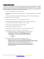
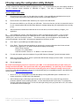
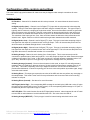
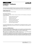
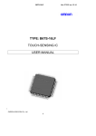
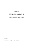
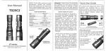
USER MANUAL
Firmware version 2.3.3
Product Description
The UMC32 is an OEM/DIY product that allows Electronic Musicians, Multimedia Artists and Experimenters the ability
to create custom user interfaces to control any software application that supports the MIDI protocol. The UMC32
provides the essential core (microcontroller, power supply, USB functionality) to allow the user to easily implement
their choice of control elements (example: switches, pots and or faders). The UMC32 will also translate data from
your MIDI host application into logic levels for driving LEDs, Relays and more.
•
Easy to implement with little or no electronics experience.
•
32 individually configurable inputs or outputs that send or receive user defined MIDI data with any MIDI host
application.
•
64 I/O’s can be achieved by linking two UMC32’s together using the UMC-Linker board (sold separately).
•
Multiple units can co-exist on the USB bus.
•
Small printed circuit board (1.6” x 2.7”) allows creating portable end devices
•
True plug-and-play (USB-MIDI class compliant drivers are provided by the operating system)
•
Compatible with all versions of Mac OS X, Windows 7 / Vista / XP / 2000
•
USB bus powered. A single USB cable handles power and data
•
No programming is necessary (No code to write).
•
Upgradeable firmware via USB using Windows XP / Vista bootloader utility (32 bit only)
•
Simple configuration of Digital or Analog channels via onboard DIP pack
•
Using extended MIDI commands, complex MIDI mappings can be realized including:
o Individual selection of each I/O’s corresponding MIDI channel (1 to 16)
o Individual selection of each I/O’s corresponding MIDI message value
o Individual selection of each I/O’s corresponding MIDI message type(s):
Note On
Poly Pressure
Controller
•
Individual selection of each I/O’s corresponding hardware type including:
o Digital Input with pull-up (active low) - For use with SPST tactile switches
o Digital Input (active low) - For receiving messages from sensors with active low TTL outputs
o Digital Input (active hi) - For receiving messages from sensors with active high TTL outputs
o Analog Input - For connection to potentiometers, joysticks, faders etc.
o Analog Input (Inverted) - Same as above, except that MIDI data is inverted.
o Digital Output (Active High) – For driving LED’s, Relays, or high power FETs etc.
o LED Output with Blink –For blinking of status LED's (see manual for details).
o More I/O types to comeF
PCB rev 1 & 2, Firmware v2.3.3, Datasheet: 03/17/2010 3:18 PM
© 2007 - 20010 Hale Microsystems LLC, http://www.halemicro.com, [email protected]
2
Before proceeding it is strongly recommended that you read and understand the precautions section of this manual.
Failure to observe the recommendations may void your warranty.
Firmware Revision
In response to customers’ requests there have been many revisions to the UMC firmware. It is important that you
ensure that you are reviewing the correct manual that corresponds with the firmware version of your device.
Indicator LED
The indicator LED (LED1) can be found next to the USB connector. This LED provides information about the state of
the UMC. When connected, your computer will recognize the UMC and load the class compliant USB-MIDI class
device driver that is provided by your operating system. The LED will stay on until communication with your host
application begins. At this point the LED will flicker when MIDI traffic between the host application and the UMC
occurs.
Firmware Update
When the UMC is plugged into the USB port it first checks the state of the shift pin, if it is pulled low (your switch is
being held) then the UMC will enter bootloader mode and prepare to accept a firmware update. Information regarding
firmware updates will be made available on our website at http://www.halemicro.com
Connecting multiple UMC32’s to the USB bus.
For connecting more than 1 UMC32 to the same computer it is recommended that you install one of 8 available
firmware binaries on your UMC32. First download the latest firmware set from the Hale website. The zip file will
contain multiple firmware revisions with “.DLD” extensions. Next download and install the UMC32’s firmware update
utility, follow the directions provided by the utility and select the appropriate firmware. In this case you would select
“UMC32_v215_051809_Dev02.dld” for device number 2. Each firmware binary is slightly different in that they
contains a unique USB product ID as well as a unique Driver Name that allows the operating system to identify it on
the USB bus. When using more than one UMC32 it is also recommended that all UMC I/Os on Device 1 be set for
MIDI channel 1, and Device to for MIDI channel 2 etc. As there are many implementations by host applications and
operating system drivers this is a full-proof way of uniquely and consistently identifying each UMC that is connected to
your system regardless of your MIDI application or operating system.
Linking of two UMC32’s to obtain 64 I/O channels
New in firmware revision 2.26 is the ability to link up to 2 (two) UMC32s together using the 5 pin aux port located at
the far end of the board between Bank2 (09-16) and Bank3 (17-24). The linking is achieved by connecting the
corresponding pins with jumpers or the “UMC linker” board. Master / Slave operation is auto-detected making the link
hassle free. Please keep in mind that slaved units are not accessible to the Configuration utility. Therefore each
UMC must be configured prior to being linked. The total current for both devices must not exceed 500mA.
*All boards that have shipped from Hale Micro before Nov 2009 may have R3 & R4 populated on the PCB. For the
linking function to work properly, both of these resistors should be removed. The removal process can be performed
with 2 soldering irons by simultaneously heating both sides of the resistors terminals.
PCB rev 1 & 2, Firmware v2.3.3, Datasheet: 03/17/2010 3:18 PM
© 2007 - 20010 Hale Microsystems LLC, http://www.halemicro.com, [email protected]
3
I/O setup using the configuration utility (Default)
To begin, download and install the UMC32 configuration utility. It is recommended that your video display should be
set at a minimum screen resolution of 1024x768 or higher).
The utility is available for download at
http://www.halemicro.com
How to configure (quick start):
1)
Disconnect any wires, ribbon or usb cables from the UMC. Close any MIDI host applications that may be
running as the configuration utility needs exclusive access to the UMC’s MIDI I/O.
2)
Ensure that all of the UMC32’s DIP switches (1 thru 10) are in the ON Position.
3)
Reconnect the UMC32 to your PC with your USB cable. If this is the first time you have connected this device
to your computer please wait until Windows displays a message stating that your hardware/devices are ready
to use
4)
After windows has installed and loaded the drivers for the device, launch the UMC32_ConfigUtil_v113
application.
5)
In the “MIDI Ports” section, select the IN Device, and the corresponding OUT device. If you are using
Windows XP the UMC32 will show up as “USB Audio Device”, under Vista and Windows 7 it will show up as
“UMC32_D0x”, where x is the device number. .. The device number you see will depend on the firmware that
you have bootloaded into the UMC. All devices are shipped from the factory as D01.
6)
Click “Open” to open MIDI input and MIDI output ports.
7)
Click “Read”. This will cause the application to grab all of the current configuration data for the selected
device into the application. The ‘Status’ window should display the following:
“Status: Read Complete”
“Firmware: v2.x.x (Build Date)”
“USB PID: 0x0DEx / Device # x “ Where x is the device number.
8)
For each I/O channel select the Hardware I/O type, MIDI Channel, Message Type and message number.
9)
When you are finished, click on “Write” to update the UMC with the changes you have made. Your device is
now configured and ready for use.
10)
Exit the application.
Be careful connecting any sensors or controls to your UMC. It is recommended that you triple check your
wiring to and from the UMC. Take special care when using Output Mode(s). It is quite easy to set a channel
for output mode and mistake it as an input when connecting your pots or switches causing a short circuit.
If you are in doubt about the hardware type of your control please post your compatibility question in the UMC32 user
forums located at http://forums.halemicro.com/.
•
New in v2.2.7+ is a simple MIDI monitor that will display incoming MIDI data bytes in hexadecimal. For
further convenience, the DIP pack is also displayed.
•
After modifying a type, performing a right mouse button click outside of any control will copy the same
parameter selection to the remaining channels. In most cases this allows for quick setup. For example by
selecting “IN Digital w/Pullup(10ms)” for I/O # 09, then right clicking in the grey area next to “09”, I/Os 10 thru
32 assume the same channel type.
PCB rev 1 & 2, Firmware v2.3.3, Datasheet: 03/17/2010 3:18 PM
© 2007 - 20010 Hale Microsystems LLC, http://www.halemicro.com, [email protected]
4
Configuration utility controls and settings
This is the UMC32’s physical hardware I/O channel see the pin diagram under example connections for more
information.
Hardware I/O Types:
I/O Disabled – Channel I/O is disabled and will not be processed. All unused channels should use this
setting.
IN Digital w/pullup (2ms) – Channel is set for Digital (TTL) input with the microcontroller’s internal pullup
enabled. This type is the same digital input mode when using the onboard DIP pack. This type of input is
typically used to connect to a single pole single throw switch. One end of the switch connects to ground the
other will connect to this I/O channel. This type is also useful for sensors that pull the line low (active low)
when the sensor is actuated and release the line or place it in Hi-Z state when the sensor is not actuated.
The variations of this input type 2ms, 5ms, 10ms and 20ms denote the debounce delay utilized when the
switch is read. Higher values are useful for switches that generate unwanted noise when actuated.
IN Digital (Active Low) - Channel is set for Digital (TTL) input. This type is used when accepting a high or
low signal from the output of a powered sensor on/off type output. This is for sensors that pull the line low
when the sensor is actuated and high when it is not actuated.
IN Digital (Active High) - Channel is set for Digital (TTL) input. This type is used when accepting a high or
low signal from the output of a powered sensor with a on/off type output. This is for sensors that pull the line
high when the sensor is actuated and low when it is not actuated.
IN Analog Average - Channel is set for Analog (0v to 5volts) inputs. This is most commonly used for
connection to potentiometers, faders and joysticks. It can also accept the input from other sensors that output
a voltage in the range of 0 to 5 volts. In this mode, an input of 5 volts will generate a message value of 127
(0x7F hex), whereas an input of 0 volts (ground) will generate a message value of 0 (0x00 hex).
IN Analog Average (Inverted) – Same as above however in this mode, an input of 5 volts will generate a
message value of 0 (0x00 hex), whereas an input of 0 volts (ground) will generate a message value of 127
(0x7F hex). This mode is especially useful if you happen to solder the +5V and Ground terminals on a
potentiometer backwards. Instead of reopening your device to correct the problem by resolder again, simply
select this mode instead.
IN Analog Direct – This input type reports the raw value of the ADC and does not perform any averaging on
the sampled data. This mode is most useful for raw performance and is best used with so force sensing
resistors or soft pots.
IN Analog Direct (Inverted) – See above for more information.
OUT Digital (Active High) – If a corresponding MIDI message is received by the UMC with a value of 0 then
the output for this channel will be low or 0 volts (ground). If the corresponding MIDI message is 127 (0x7F in
hexadecimal) then the output will be high or +5volts.
OUT LED Blink –This mode functions like the OUT Digital above however, values between 64 and 127 shall
turn the LED on values between 1 and 63 shall blink the LED. Zero value turns the LED off.
IN Analog Average (MIDI OFF) – This input type is used for internal testing and should not be used.
PCB rev 1 & 2, Firmware v2.3.3, Datasheet: 03/17/2010 3:18 PM
© 2007 - 20010 Hale Microsystems LLC, http://www.halemicro.com, [email protected]
5
MIDI CH
Here you can select the desired MIDI Input or output channel that corresponds to the UMC32’s physical hardware I/O
channel. You can select 1 of 16 channels. By convention it is recommended that you set this to be MIDI channel 1 for
UMC32 Dev01, MIDI channel 2 for UMC32 Dev02 etc.. As every MIDI host application deals with multiple USB-MIDI
devices differently. This has proved to be a method ensures that all host learned controls will remain consistent when
Windows enumerates your UMCs that occurs when Windows starts up.
Message Type
Note On (0x90) – This is the recommended message type for input or output controls that are Boolean or ON/OFF.
Such controls are switches, or other sensors that output a logic level high or low. When this mode is selected for a
channel there are certain conditions that will cause a note off (0x80) message to be generated. Instead of generating
a Note On with a velocity of zero the UMC will generate a true note off message. This applies to IN Digital w/Pullup
(active low), IN Digital (Active Low), IN Digital (Active High) hardware Input types. For the hardware Output type(s),
both note on velocity of 0 as well as Note off velocity zero are interpreted correctly by the UMC.
Poly Pressure (0xA0) & Controller (0xB0): These message types are recommended for I/O’s that are configured as
Analog inputs.
Msg Num (Message Number)
Depending on the Message type the message number may be interpreted differently. The allowable range for this
parameter is 0 to 127 (0x00 to 0x7F in hexadecimal). With regards to note on and poly pressure message types
these values are indicative of note numbers or keys on a piano keyboard. For instance C-1 is 0, C#4 is 61 and
G9 is 127.
Default:
This will initialize all controls to the following: IN Digital w/pull-up (active low), MIDI Channel X (where X = the device
#), Note On, message number 36 thru 67.
All Off:
This will initialize all controls to the following: I/O Disabled, MIDI Channel X (Where X = the device #), Note On,
message number 36 thru 67.
PCB rev 1 & 2, Firmware v2.3.3, Datasheet: 03/17/2010 3:18 PM
© 2007 - 20010 Hale Microsystems LLC, http://www.halemicro.com, [email protected]
6
I/O Setup using the onboard DIP switches (Legacy Mode)
Legacy Mode (DIP 10 off).
In legacy mode the UMC32’s I/O may be configured as digital or analog inputs. By setting the onboard DIP switches
(DIP 1 thru 9) appropriately, various input types can be achieved. The UMC32 ships with the all DIP switches in the
on position which requires configuration to be performed by the PC configuration utility. In order to change from the
default setting, please remove the protective tape (if present). It is important to note that all unused channels be set
to digital input mode (factory default) in order to suppress spurious controller data that would otherwise be sent to
your host application.
Analog Mode (IN Analog Average)
Channels that are configured as analog inputs are sampled and converted into MIDI continuous controller (CC#)
messages and sent to your host application. Analog mode is usually the choice when connecting a potentiometer or
fader. For the sake of simplicity, each input channel maps directly to its corresponding continuous controller (CC)
number on MIDI channel 1. For example assume that input channel 1 on the UMC has a fader connected to it and is
configured for analog input. When the fader is changed it will output controller messages on CC#01, MIDI channel 1.
PCB rev 1 & 2, Firmware v2.3.3, Datasheet: 03/17/2010 3:18 PM
© 2007 - 20010 Hale Microsystems LLC, http://www.halemicro.com, [email protected]
7
Digital Mode (IN Digital w/pullup 2ms)
Digital mode is usually selected to determine the state of a switch for triggering MIDI notes. Channels that are
configured for digital mode will output MIDI note data on channel 1. For example when a button is pressed then a
note on message will be sent, when the button is released a note off message will be sent.
Midi Output Mapping
The above input types shall use the following messages. In legacy mode all data is send on MIDI channel 1.
I/O
Channel
1
2
3
4
5
6
7
8
9
10
11
12
13
14
15
16
17
18
19
20
21
22
23
24
25
26
27
28
29
30
31
32
Master
Digital
Note #
Slave
Digital
Note #
Master
Analog
CC#
Slave
Analog
CC#
Key Dec Hex
Key Dec Hex
Dec Hex
Dec Hex
C
C#
D
D#
E
F
F#
G
G#
A
B
C
C#
D
D#
E
F
F#
G
G#
A
B
C
C#
D
D#
E
F
F#
G
G#
A
B
C
C#
D
D#
E
F
F#
G
G#
A
B
C
C#
D
D#
E
F
F#
G
G#
A
B
C
C#
D
D#
E
F
F#
G
G#
0
1
2
3
4
5
6
7
8
9
10
11
12
13
14
15
16
17
18
19
20
21
22
23
24
25
26
27
28
29
30
31
32
33
34
35
36
37
38
39
40
41
42
43
44
45
46
47
48
49
50
51
52
53
54
55
56
57
58
59
60
61
62
63
36
37
38
39
40
41
42
43
44
45
46
47
48
49
50
51
52
53
54
55
56
57
58
59
60
61
62
63
64
65
66
67
24
25
26
27
28
29
2A
2B
2C
2D
2E
2F
30
31
32
33
34
35
36
37
38
39
3A
3B
3C
3D
3E
3F
40
41
42
43
68
69
70
71
72
73
74
75
76
77
78
79
80
81
82
83
84
85
86
87
88
89
90
91
92
93
94
95
96
97
98
99
44
45
46
47
48
49
4A
4B
4C
4D
4E
4F
50
51
52
53
54
55
56
57
58
59
5A
5B
5C
5D
5E
5F
60
61
62
63
00
01
02
03
04
05
06
07
08
09
0A
0B
0C
0D
0E
0F
10
11
12
13
14
15
16
17
18
19
1A
1B
1C
1D
1E
1F
PCB rev 1 & 2, Firmware v2.3.3, Datasheet: 03/17/2010 3:18 PM
© 2007 - 20010 Hale Microsystems LLC, http://www.halemicro.com, [email protected]
20
21
22
23
24
25
26
27
28
29
2A
2B
2C
2D
2E
2F
30
31
32
33
34
35
36
37
38
39
3A
3B
3C
3D
3E
3F
8
General Precautions
The UMC is designed to protect against short circuits, over current conditions, transient voltages and electrostatic
discharge. However, we ask that you observe some simple guidelines when working with the UMC. Failure to do so
may cause damage to your equipment and/or void your product warranty.
o
Do not solder any wires or attempt to make any modifications to the UMC directly.
o
Do not connect the “+V” (+5 Volts DC) terminal to G (Ground). When this occurs, it is commonly
referred to as a “short circuit”.
o
Always unplug the USB cable from the device before modifying connections on the UMC.
o
As with all electronic devices, observe proper ESD handling practices. Always handle the printed
circuit board (PCB) by the edges, never touch the top or bottom.
o
Never allow the UMC to touch a wet or conductive surface.
o
Do not use any external voltage source to power devices that are connected to the UMC.
o
The maximum recommended current per channel is 8mA..
o
You may use the +5V and Ground pins off each bank to power other devices such as LED’s however
the maximum recommended is 80mA.
o
As an additional precaution, we strongly recommend using a powered USB hub when experimenting
with the device. Once you have finalized your project, and are sure you do not have any short circuits
then you may connect the UMC directly to your computer’s USB input. This is especially important
when interfacing with a laptop, as damage to your laptop could be substantial.
o
This product is offered to the end user in a non-enclosed OEM form, it is the responsibility of the end
user of this product to ensure that they comply with local regulations pertaining to unintentional radio
frequency emissions. In the United States, this pertains to FCC rules and regulations, Part 15,
Section B.
PCB rev 1 & 2, Firmware v2.3.3, Datasheet: 03/17/2010 3:18 PM
© 2007 - 20010 Hale Microsystems LLC, http://www.halemicro.com, [email protected]
9
Example Connections
Although there are a seemingly infinite number of types of control elements (potentiometers, switches etc.)
that you can connect to the UMC, here are a few examples of how to connect the most common types.
* Please note that connection to +5V is not necessary for any SPST switch.
PCB rev 1 & 2, Firmware v2.3.3, Datasheet: 03/17/2010 3:18 PM
© 2007 - 20010 Hale Microsystems LLC, http://www.halemicro.com, [email protected]
10
Pin Diagram
* Ribbon cables show above are sold separately (RB10KIT)
Mechanical Specifications
Please note that an alternative method to mounting the UMC to your enclosure via screws and standoffs is to
simply use double backed 3M VHB tape. Be sure that everything is working correctly before affixing to
chassis as any attempt to remove UMC affixed via from the chassis will place stress on the circuit board.
Regardless of the mounting method you choose, please take care that the exposed solder joints on the
bottom of the UMC do not make contact with your enclosure.
PCB rev 1 & 2, Firmware v2.3.3, Datasheet: 03/17/2010 3:18 PM
© 2007 - 20010 Hale Microsystems LLC, http://www.halemicro.com, [email protected]
11
Electrical Specifications
Exceeding the absolute maximum ratings below may cause permanent damage to the device.
• Storage temperature:
-20ºC to + 70ºC
• Operating temperature:
0ºC to + 50ºC
• Operating voltage (power supplied via USB bus):
5.4 Volts DC max
• Max recommended current per channel
8mA
• Maximum device current:
*200mA (R1 & R2 PCB’s with a “C” PTC)
• Maximum device current:
*250mA (R1 & R2 PCB’s with a “D” PTC)
• Maximum device current:
*500mA (R2 PCB’s with a “F” marked PTC)
*Check the component marking for PTC1
Troubleshooting
Here is a list of common questions we anticipate you may run into. We will periodically add to this as new
questions arise.
Q1:
A few pots are generating data even though I’m not moving them.
Verify that the pots are clean (CAIG Labs DeoxIT D5 works very well). If you have long wires
consider making them shorter. Generally speaking you should try to keep wire lengths as short as
possible. You might also try placing a 0.1uF capacitor across the power and ground inputs of your
potentiometer or fader. (Example: Digikey.com # BC1084CT-ND).
Q2:
Adjacent channels appear to affect one another.
Check the resistance with your multi-meter between the signal inputs of each channel. It should read
at least 1 Mega ohm. Also verify that your DIP switch pack is set correctly. Channels with switches
attached to them should be set for digital. Channels with fader or rotary potentiometers should be set
for analog mode. All unconnected channels should be set for digital mode.
Q3:
My MIDI application is seeing a lot of spurious controller data from the UMC, I do not have any
control elements connected to those channels.
Each time the USB is plugged into the UMC, it checks the state of the DIP pack to set each channel
to analog or digital mode. Channels that are left “floating” or in an undetermined state will generate
noise unless that are pulled high or low with an external resistor. Any channel that is set for analog
mode must be connected to a source (potentiometer) or it must be connected to a 10K resistor that is
connected to ground or +5 volts. Double check the DIP switches to confirm that they are set correctly
then restart the UMC.
Q3:
I plug the UMC into my USB port but it appears to be dead.
Disconnect the UMC from the USB bus immediately and check for any short circuits. Reboot your
computer and/or power cycle your USB hub. Make sure that the Shift pin (P1[3]) is not connected
when connecting the USB cable as this will cause the unit to startup in the bootloader mode.
Q4:
What to do when you receive an OS error about a surge of a USB device.
This generally happens when the user short circuits the +5V and power lines. See Q3 for remedy.
Q5:
When I turn a pot one way (clockwise), my application turns it another (counter clockwise).
Swap the V+ and G lines on your potentiometer, or perform a controller invert in your host software.
Q6:
If I disconnect the UMC while my host application is running, then re-connect again the host
does not see the UMC.
In our testing, Mac OS X had no problems with this. Depending on the application under Windows
XP you may need to re-launch your host application.
Q7:
How do I change the default MIDI output mapping ?
Refer to the advanced configuration mode for details.
PCB rev 1 & 2, Firmware v2.3.3, Datasheet: 03/17/2010 3:18 PM
© 2007 - 20010 Hale Microsystems LLC, http://www.halemicro.com, [email protected]
12
Limited Warranty
Hale Microsystems LLC warrants this product to be free of manufacturing defects for a period of 90 days
(USA only). If you feel that there is a defect with your device, please email technical support with a detailed
description of the problem: [email protected]. In most cases we will issue a replacement. Please note
that the unit must be shipped back in its original packaging and be in original saleable condition. We will not
accept the return of any product that has been modified beyond factory condition.
Disclaimer
Neither the whole nor any part of the information contained herein or the product described in this datasheet
may be adapted or reproduced in any material or electronic form without the prior written consent of the
copyright holder. This product and its documentation are supplied on an as-is basis, and no warranty as to
their suitability for any particular purpose is either made or implied. Hale Microsystems LLC will not accept
any claim for damages whatsoever arising as a result of use or failure of this product. Your statutory rights
are not affected. This product is not intended for use in any medical appliance, device or system in which the
failure of the product might reasonable be expected to result in personal injury. This document provides
preliminary information that may be subject to change without notice.
Windows is a registered trademark of Microsoft Corporation in the United States and other countries.
PCB rev 1 & 2, Firmware v2.3.3, Datasheet: 03/17/2010 3:18 PM
© 2007 - 20010 Hale Microsystems LLC, http://www.halemicro.com, [email protected]
13