1
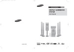
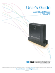
VECTOR
USERS MANUAL
Body Scanner Tray is the base upon which to
position Body Scanner. Rubber strips on the
Tray’s inside edges and insulating feet on thebottom of Body Scanner help prevent metal-tometal contact between Tray and Body Scanner.
Insert Body Scanner Tray below vehicle’s center
section (see Figure 8) and place the Body
Scanner on Tray (see Figure 9). Cable port must
be under the left side of vehicle. This positioning allows the Body Scanner to be synchronized
with computer program.
Figure 8
Body Scanner does not need to be square to the
vehicle or level. Make sure, however, it remains
in the Tray and the Tray is stable. It is permissible to reposition Tray any time or shift the Body
Scanner in the Tray. Vector recalibrates any
repositioning in its next measurement cycle.
Targets
All Targets are numbered and their reflective
faces bear a unique code. (See Figure 10.) Most
Targets are interchangeable, although some have
specific uses. An assortment of clips, extensions
and other attachment devices provide flexibility
in Target placement. All specifications are provided from reference hole and bolt centers.
Figure 9
Targets 1 - 36 (and optional Targets 37-40) are
interchangeable depending on length of pendant
needed. Optional Targets 41 and 42 are used
with a Target Base when measuring lower control arms. Optional Targets 43, 44, and 45 are
used with the Optional Upper Body Bar when
measuring strut tower and other upper body reference points.
9