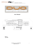
1
Hardware Interface User Manual Page 1 of 24 BajuSoftware, LLC Version 1.8 – August 2015 ELITE Hardware Interface User Manual Table of Contents Introduction .................................................................................................. 3 Technical Requirements ............................................................................... 4 Installation Procedure................................................................................... 5 Configuration ............................................................................................. 10 Licensing and Activation ............................................................................. 11 Software Activation ...................................................................................................... 11 Flight Control Calibration ............................................................................ 14 Motion Range .............................................................................................................. 14 Control Sensitivity ........................................................................................................ 16 Button Assignments ................................................................................... 17 AP4000 GPS ............................................................................................................... 17 AP4000 ADF................................................................................................................ 17 AP 4000 AUX Switches ............................................................................................... 18 Electric Trim................................................................................................................. 18 Yoke Buttons ............................................................................................................... 18 Network & Elite Interface Configuration ....................................................... 19 Network Settings ......................................................................................................... 19 Misc Settings ............................................................................................................... 20 Elite Interface Settings ................................................................................................. 21 Miscellaneous ............................................................................................ 22 AP4000 ADF Radio ..................................................................................................... 22 AP4000 NAV/CRS/HDG Module ................................................................................ 23 Pro Panel 2 .................................................................................................................. 23 Functions not implemented.......................................................................................... 23 Copyright © 2015, BajuSoftware, LLC. All rights reserved. Page 2 of 24 ELITE Hardware Interface User Manual Introduction This Interface Software provides the connection of Elite Flight Controls and Avionics to the X-Plane 10 Simulator. The following Elite Hardware is supported by this Interface: Elite Pro Panel II Elite Standalone Throttle Quadrant (Multi or Single Engine and King Air) Elite Rudder Panels Elite AP4000 Avionics Stack Elite AP3000 Avionics Stack (Apollo or Trimble GPS not supported) Elite COM/NAV Radio (2 modules supported for COM/NAV1 and COM/NAV2) Elite ADF Radio Module Elite DME Radio Module Elite Auto Pilot Module Elite Altitude Pre-Select and Audio Panel Module Elite Transponder Module Elite NAV/CRS/HDG Module Elite GNS430 Module (2 GPS modules supported) Elite GNS530 Module All hardware elements can be used together, or either one of them standalone or any other combination. Other hardware can also be used in combination with Elite Hardware as well. The Interface is compatible both the 32bit and 64bit mode of X-Plane 10. The Interface software contains two parts, the X-Plane Plugin and the Hardware Driver Interface. In the next sections we explain how to install, configure and use this interface software in combination with Elite Hardware and X-Plane 10. Copyright © 2015, BajuSoftware, LLC. All rights reserved. Page 3 of 24 ELITE Hardware Interface User Manual Technical Requirements Hardware Operating Software Flight Simulator(s) Processor Any Dual Core Processor or greater Memory 4GB (32 Bit), 8GB (64 Bit) Disk Space 1 GB (approx. Flight Controls/Avionics See list on previous page Windows Vista 32 or 64 Bit Windows 7 32 or 64 Bit Windows 8 32 or 64 Bit Windows 10 32 or 64 Bit X-Plane 10 10.20 or greater 10.30 if using the GNS430 Module IMPORTANT! This software only supports Elite Devices with a USB Interface. Serial Devices (RS232) are NOT supported, even when used with a serial to USB converter! The Interface also requires at a minimum the .Net Framework 4.0 Extended. The .Net Framework 4.0 Client Profile is not sufficient! During the install process, there is an option to install this required component. Copyright © 2015, BajuSoftware, LLC. All rights reserved. Page 4 of 24 ELITE Hardware Interface User Manual Installation Procedure Step 1 Locate the Installation Package on your computer. If you have downloaded the package, check in your Downloads Folder. Double click on the installation package, XPlaneInterfaceElite64.exe Step 2 IMPORTANT! Follow the installation instructions on the screen. Click [Next >] to continue. Copyright © 2015, BajuSoftware, LLC. All rights reserved. Page 5 of 24 ELITE Hardware Interface User Manual The installation process chooses the default X-Plane 10 installation folder, which is located on your desktop. If you have installed X-Plane 10 to a different folder, use the Browse button to locate the top level (root) folder of your X-Plane 10 installation. This is very important, the folder has to match your X-Plane top level folder! Click [Next >] to continue. This will provide you with the option to change the Start Menu folder name. Accept the default or type a new name and click [Next >] to continue. Copyright © 2015, BajuSoftware, LLC. All rights reserved. Page 6 of 24 ELITE Hardware Interface User Manual Review your selected options then click [Install] to continue. Wait for the installation to finish, the following screen will appear: This screen will allow you to install required additional driver software that the Elite Interface Software requires to operate. You might have already some of the software installed. In this case you un-check the tick box in front of the software option. Copyright © 2015, BajuSoftware, LLC. All rights reserved. Page 7 of 24 Panel Builder Add-On MFD GPS User Manual The first option, .Net 4.0 Extended, is required for the Interface to work. Leave this option checked. I you have this or a newer version already installed on your computer, you will get the following screen: In this case you can only click the [Close] button. Otherwise click the [Continue] button to install it. Copyright © 2015, BajuSoftware LLC. All rights reserved. Page 8 of 24 ELITE Hardware Interface User Manual You might also have the Microsoft Visual C++ runtimes already installed. Those might be also required by other programs on your computer. If you are not sure, you can leave the option(s) checked. If the software is already installed, you get the following screen: This screen indicates that the software is already installed. Click the [Close] button. You might also get the following screen (This is for the 64bit version of the C++ software): Again, the software is already installed. Click the [Close] button. The third software option is for the Elite USB Driver. This software is required for the Elite hardware to be recognized by Windows. Make sure you install the USB Driver before attaching any Elite hardware. If you have any Elite IFR software installed, you can take the checkbox off as the USB drivers are very likely to be installed already. This completes the installation procedure. Copyright © 2015, BajuSoftware, LLC. All rights reserved. Page 9 of 24 ELITE Hardware Interface User Manual Configuration During the installation process, a shortcut to the Interface and the User Manual has been created and placed onto your desktop. A shortcut to the Interface has also been placed in the Windows Startup folder. This will automatically start the Interface next time you start your computer. If your Elite Hardware is not already attached, attach it now to the computer and make sure that power is applied to all devices. If you use the ProPanel II, turn the Panel Master Key to the ‘On’ position. Double click the Elite HW Interface Icon on your desktop. The hardware Interface is started and placed into the taskbar into the system icon tray. You will see the following message for a short time appearing on the bottom right of your screen: This indicates that the Interface has been started. The notification will disappear after a short while and the icon will be placed in the tray icon bar. To see the icon again after the message has disappeared, click on the up arrow in the system task bar on the bottom right of your screen: Before using the hardware with X-Plane for the first time, you need to configure the interface and calibrate the flight controls (see next chapter). Copyright © 2015, BajuSoftware, LLC. All rights reserved. Page 10 of 24 ELITE Hardware Interface User Manual Licensing and Activation The Elite Hardware Interface needs to be activated. If there is no valid Activation present, the Interface will work in a timed trial mode. The Interface will operate for 10 Minutes and then it will shut itself down. Software Activation Step 1 – Request Activation Code A License can be purchased online at http://www.simplugins.com. After the purchase a Serial Number will be e-mailed to the purchaser. This Serial Number in combination with the e-mail address will be used to request an activation code. Click on Licensing and enter the information under Step 1. Then click on [Request Activation Code] and wait for the Activation Code to arrive in your Inbox. This process can take up to 24 hours, please be patient. This option requires an Internet connection on your computer. Copyright © 2015, BajuSoftware, LLC. All rights reserved. Page 11 of 24 ELITE Hardware Interface User Manual An alternative method is to click on [Manual Request]. This will show you the information that is required to issue you an Activation Code. You can use this information to use a different computer and request the Activation code by e-mail. Copyright © 2015, BajuSoftware, LLC. All rights reserved. Page 12 of 24 ELITE Hardware Interface User Manual Step 2 – Enter Activation Code After receiving the Activation Code via E-Mail, it has to be entered together with the same e-mail address that has been used during the request in Step1. Click on Licensing and enter the information under Step 2. Then click on [Activate Product]. You will get a message that the Activation was successful or not. If you get ‘failed’ message, make sure you entered the correct E-Mail Address and the correct Activation Code you received after performing Step 1. Copyright © 2015, BajuSoftware, LLC. All rights reserved. Page 13 of 24 ELITE Hardware Interface User Manual Flight Control Calibration Motion Range Before using your Elite Flight Controls for the first time you need to calibrate their motion range and center point. Right Click on the Elite HW I/F Icon in the system taskbar and select Configure. The configuration screen is displayed as shown above. There are several pages to this application, accessible via the buttons on the top menu bar. The first screen displays what Elite devices are connected to your system. Click on the Calibrate button. The calibration for Rudder Pedals is displayed. Copyright © 2015, BajuSoftware, LLC. All rights reserved. Page 14 of 24 ELITE Hardware Interface User Manual The Calibration screen allows you to calibrate each flight control (yoke and rudder pedals), the toe brakes, the throttle quadrant and the rudder trim. Calibrating the flight controls includes setting the extent of the motion and the center point. You can test the motion range by moving your controls now. This will move the black pointer. The read pointers indicate the limit of the movement the control can perform. Initially they are set to the theoretical maxim for each control. Click on Reset Calibration. This will move the red pointers to the current position (black pointer). Now move the flight controls to its full motion extend in all directions. You will see the red pointer moving to their respective maximum position. The values are saved automatically. Some controls require setting the center point of the flight control. This applies to the rudder pedals the yoke and the rudder trim. After you calibrated the maximum motion range, let the controls return to their center (‘spring loaded center’) or position the control to the center (rudder trim). Don’t touch any control and then press the Set Center button. Repeat the above operation for each Elite Device that has flight controls by selecting the appropriate calibration page, Rudder Pedals, Yoke, Throttle Quadrant and Rudder Trim. Copyright © 2015, BajuSoftware, LLC. All rights reserved. Page 15 of 24 ELITE Hardware Interface User Manual Control Sensitivity By default, each flight control (yoke and rudder pedals), the toe brakes, the throttle quadrant and the rudder trim movements are sent to the flight simulator in a linear motion. This translates each position of a control to its counterpart in the flight simulator. Because of the sensitivity of the controls, even slight movements of the controls will have an impact on the flight simulator control. This can lead to ‘over-controlling’ the airplane. This is visible for example when taxiing and during the take-off run where it is difficult to keep the airplane in a straight line. For this reason we have included a sensitivity compensation configuration option. This is available for the flight controls and also the throttle quadrant and the rudder trim. There are 5 settings (levels) to choose from, with each making the control less sensitive at the beginning of the movement range. The chart below shows the curves for each setting. The different settings are chosen by moving the control sensitivity slider for each control. The further the slider is moved to the right, the less sensitive the control becomes. The furthest position to the left is the default, indicating a linear movement. Choose a setting that ‘feels right’ to you. Copyright © 2015, BajuSoftware, LLC. All rights reserved. Page 16 of 24 ELITE Hardware Interface User Manual Button Assignments This page on the configuration screen allows you to customize some button assignments, mainly for the Elite AP4000 Avionics. AP4000 GPS This allows you to choose which GPS device the AP4000 controls. Currently there are 3 options, the built-in X-Plane GNS 430, the Reality XP GNS 430 Add-On or the SimAvio GNS430/530. As the Reality XP GPS does not support 64bit, this option will only work with XPlane 10 running in 32bit mode. The SimAvio GPS currently has a bug in the 64bit driver, so you need to start X-Plane in 32bit Mode. AP4000 ADF Here you can set the display for each ADF Timer, the flight time and the elapsed timer. You can choose from either a HOUR:MINUTE (HH:MM) or a MINUTE:SECOND (MM:SS) display. Here you can also choose to play a sound when the count-down ADF Timer has expired (reached zero). For more information regarding the ADF Operation, see the separate chapter for the ADF. Copyright © 2015, BajuSoftware, LLC. All rights reserved. Page 17 of 24 ELITE Hardware Interface User Manual AP 4000 AUX Switches There are 2 AUX switches on the AP 4000 on the remote control section of the Avionics stack (the bottom section). You can assign different functions to each of the switches. Currently only the Igniters for engine 1 and 2 are available. More will be added later if required. Electric Trim This setting allows you to set how many notches for each button press the trim will be moved. The default is 1. Yoke Buttons Here you can specify which functions to use with both yoke buttons, the left yoke button (red) and the right yoke button (black). Use the dropdown box to select the function you wish to assign. The defaults are Left Button: PTT (‘Press to talk’). This will contact ATC. Right Button: CWS(‘Control Wheel Steering’). Note: If you are using PilotEdge, make sure you have one of the buttons assigned to PTT to contact and talk to the PilotEdge Air Traffic Controllers. Copyright © 2015, BajuSoftware, LLC. All rights reserved. Page 18 of 24 ELITE Hardware Interface User Manual Network & Elite Interface Configuration Network Settings The Elite Hardware interface communicates to the flight simulator via a network connection. The flight simulator has a plugin installed that receives and sends information between the Hardware Interface and the Flight Simulator. This allows the Elite Hardware to be installed in a different computer to the Flight Simulator. Besides X-Plane 10, other flight simulator will be supported in the future. Click on the Network Button. The Network Settings are configured by default to have the Flight Simulator and the Elite Hardware Interface installed in the same computer. Copyright © 2015, BajuSoftware, LLC. All rights reserved. Page 19 of 24 ELITE Hardware Interface User Manual If you have the Flight Simulator installed on a different computer, add the Flight Simulators IP Address in the edit box IP Address as shown above. (127.0.0.1 specifies the local computer). You also need to modify the IP Address of the Flight Simulator plugin to indicate the IP Address of the computer with the Elite Hardware. The configuration file for the plugin can be found in [X-Plane 10 Main Folder\resources\plugins\Elite Plugin. It is called Sender.cfg. Edit the line for the IP Address (under Client IP Address) and change it to the IP Address where the Elite Hardware is connected to: The port numbers can be left as they are unless you have a conflict with another program on your computer. Misc Settings Enable periodic updates to AP4000. This function updates all AP4000 devices every 2 seconds. This ensures that the AP4000 devices always show the correct data. This is optional and is only required if you get ‘garbled’ data displayed now and then. You can take this off and see if this is required by your system. Copyright © 2015, BajuSoftware, LLC. All rights reserved. Page 20 of 24 ELITE Hardware Interface User Manual Elite Interface Settings Note: This configuration box is only visible on computers with Windows Vista or Windows 7 installed. This configuration option is required because there is a bug in the Windows Vista & Windows 7 USB driver for USB3 devices: USB3 devices cannot be assigned a USB ID under .Net. What does this mean to you? If you are running on Windows 8 or greater, no problem. Everything works as expected. No changes are required. If you are on Windows 7 or below, you need to make sure you plug in all Elite devices into a USB2 port. Or use a USB2 hub and plug the USB Hub into a USB2 port on your computer. If you are on Windows 7 and cannot use a USB2 port on your computer, there is an alternative way of opening the Elite devices, choose Open Elite Devices by Serial Number. Unfortunately serial numbers are not unique for Elite devices of the same type, like all Nav/Comm Radios have the same serial number. If you are not using any duplicate Elite Devices, this will work. If you are using 2 Nav/Comm radios or 2 GPS Modules, this will not work! In this case you need to connect all your Elite devices into USB2 ports or a USB2 Hub connected to a USB2 port on your computer. Copyright © 2015, BajuSoftware, LLC. All rights reserved. Page 21 of 24 ELITE Hardware Interface User Manual Miscellaneous AP4000 ADF Radio The X-Plane ADF radio has only very basic functionality. The only function that is supported is the frequency dial. In order to expand the functionality, additional ADF functions have been implemented in the Hardware Interface Software. Timers The following timers are available: o Flight Time (from switch on of Avionics Master to switch off). o Elapsed Time with reset function. o Countdown Timer. The timers are accessed via the ADF FLT/ET button. Each subsequent press displays the next timer and then return to the ADF Mode. ADF mode Flight Timer Elapsed Time Count Down Timer The countdown timer can be set using the frequency dial. The SET/RST button starts the timer or resets the timer to 0:00. An optional sound is played when the timer reaches 0:00. All timers continue to run, even when the display is in ADF mode. BFO The BFO button is not supported by X-Plane. Pressing the BFO button lights up the BFO LED in the ADF Radio. No other function is initiated. ANT The ANT mode is not implemented. Pressing the ADF Button has no effect. Copyright © 2015, BajuSoftware, LLC. All rights reserved. Page 22 of 24 ELITE Hardware Interface User Manual AP4000 NAV/CRS/HDG Module NAV1/NAV2 Switch – selects the HSI Source Pro Panel 2 The un-labelled Switch to the right of Pitot Heat is assigned to Carburetor Heat Functions not implemented The following functions are not implemented as they are not support by X-Plane: AP4000 Stack and Modules: MKR BCN HI/LO Copyright © 2015, BajuSoftware, LLC. All rights reserved. Page 23 of 24 ELITE Hardware Interface User Manual ELITE Hardware Interface – X-Plane 10 User Manual Version 1.8 Copyright © 2015, BajuSoftware, LLC. All Rights reserved. No reproduction without permission Copyright © 2015, BajuSoftware, LLC. All rights reserved. Page 24 of 24