1
SM
Maximum Value for OEMs
NX70 High-speed Counters
(NX70-HSC1, NX70-HSC2)
User Manual
Important User Information
Solid state equipment has operational characteristics differing from those of
electromechanical equipment. Because of this difference, and also because
of the wide variety of uses for solid state equipment, all persons responsible
for applying this equipment must satisfy themselves that each intended
application of this equipment is acceptable.
In no event will OE Max Controls be responsible or liable for indirect or
consequential damages resulting from the use or application of this
equipment.
The examples and diagrams in this manual are included solely for
illustrative purposes. Because of the many variables and requirements
associated with any particular installation, OE Max Controls cannot assume
responsibility or liability for actual use based on the examples and
diagrams.
No patent liability is assumed by OE Max Controls with respect to use of
information, circuits, equipment, or software described in this manual.
Reproduction of the contents of this manual, in whole or in part, without
written permission of OE Max Controls is prohibited.
Throughout this manual we use notes to make you aware of safety
considerations.
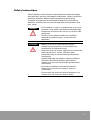
WARNING
Identifies information about practices or circumstances
which may lead to serious personal injury or death, property
damage, or economic loss.
IMPORTANT
Identifies information that is critical for successful
application and understanding of the product.
ATTENTION
Identifies information about practices or circumstances that
can lead to minor personal injury, property damage,
economic loss, or product malfunction. However, depending
on the situation, failure to follow the directions
accompanying this symbol may also lead to serious
consequences.
Contents
1. Specifications and Components................................. 9
High-speed Counter Unit Features ............................................................... 9
General Specifications ................................................................................. 12
Performance Specifications......................................................................... 12
Unit Diagram (NX70-HSC1) ......................................................................... 14
Mode Switch................................................................................................. 15
Dimensions ................................................................................................... 15
2. Operation Description .............................................. 17
Counter Architecture.................................................................................... 17
I/O Contact .................................................................................................... 18
I/O Data (Word)............................................................................................. 23
I/O Terminal .................................................................................................. 25
Mode Switch................................................................................................. 30
Pulse Output Function ................................................................................. 38
3. Specifications and Components............................... 51
High-speed Counter Unit Features ............................................................. 51
General Specifications ................................................................................. 53
Performance Specifications......................................................................... 53
Unit Diagram (NX70-HSC2) ......................................................................... 55
Mode Switch................................................................................................. 56
Dimensions ................................................................................................... 56
4. Operation Description .............................................. 57
Counter Architecture.................................................................................... 57
Terminal Block I/O ........................................................................................ 58
LED ................................................................................................................ 59
I/O Contact .................................................................................................... 60
I/O Data (Word)............................................................................................. 68
Mode Switch................................................................................................. 70
5. Precaution for Wiring ............................................... 75
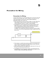
Precaution for Wiring................................................................................... 75
3
4
Safety Instructions
Please read this manual and the related documentation thoroughly
and familiarize yourself with product information, safety instructions
and other directions before installing, operating, performing
inspection and preventive maintenance. Make sure to follow the
directions correctly to ensure normal operation of the product and
your safety.
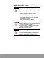
WARNING
• If this product is used in a situation that may cause
personal injury and/or significant product damage,
implement safe measures such as use of fault-safe
equipment.
• Do not use this product under any conditions
exposed to explosive gases. It may cause an
explosion.
ATTENTION
• Make sure to use an external device when
configuring the protective circuit breakers for
emergencies or interlock circuits.
• Fasten the terminal screws tightly to ensure that the
cable connection is secure. Incorrect cable
connection may cause overheating and product
malfunction.
• Operate and keep the product under the allowed
conditions directed in product specifications.
Otherwise it may cause overheating and product
malfunction.
• Do not disassemble or remodel the product.
Otherwise it may cause an electric shock or
malfunction.
• Do not touch the terminals when the power is on.
Otherwise it may cause an electric shock.
5
Do not install your high speed counter module if any of the
following conditions are present:
ATTENTION
Do not install your high speed counter module if any of
the following conditions are present:
• Ambient temperature outside the range of 0 to 55 °C
(32 to 131 °F).
• Direct sunlight.
• Humidity outside the range of 30% to 85%
(non-condensing).
• Chemicals that may affect electronic parts.
• Excessive or conductive dust, or salinity.
• High voltage, strong magnetic fields, or strong
electromagnetic influences.
• Direct impact and excessive vibration.
ATTENTION
Installing Modules on the System
1. Wire I/O cables to the terminal block of High-speed
Counter (NX70-HSC1, NX70-HSC2).
2. Turn on the power connected to the High-speed
Counter (NX70-HSC1, NX70-HSC2).
3. Turn on the main PLC power.
ATTENTION
Removing Modules from the System
1. Turn off the main PLC power.
2. Turn off the power connected to the High-speed
Counter (NX70-HSC1, NX70-HSC2) I/O.
3. Remove the wirings from the terminal block.
6
ATTENTION
Preventing PLC System Malfunctions
• Use an isolation transformer and line filter on the
incoming power to the PLC when there is equipment
using or producing high current, high voltage, or
large magnetic fields in the vicinity.
• Separate the main system groundings and other
device groundings, and use 3-way grounding.
• Do not exceed the current and power rating of the
external 24 VDC provided by the PLC power supply.
Otherwise it may cause operation errors.
• Avoid system faults due to programming errors by
reading and fully understanding the PLC instructions
set.
• Perform regular preventive maintenance on installed
systems, checking devices and wiring for potential
breakdowns and failures.
Precautions for High-speed Counter Unit Operation
When input devices like rotary encoder to High-speed Counter, or
under conditions with much noise, select “Phase differential input,
4 x” input mode.
7
8
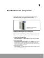
1
Specifications and Components
100Kcps High-speed Counter and 40KHz pulse output function,
combined with motor drive, enables temporary location control.
(High-speed Counter input and pulse output functions)
(Note) There is no pulse output function for 2CH type (NX70-HSC2) product
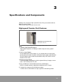
NX70 High-speed Counter Unit
NX70-HSC1: 1CH Unit
High-speed Counter Unit Features
NX70 PLC High-speed Counter (1CH type, NX70-HSC1) unit provides
40KHz pulse, as 100Kcps High-speed Counter input, and combined
with motor drive, enables temporary location control. (High-speed
Counter input and pulse output functions)
1. 100kcps High-Speed Response
High-speed response of 100kcps allows for high-accuracy speed
control and location decision control.
2. Various Input Modes
Phase differential input mode (1 x, 4 x mode) that can count
two-phase pulse of rotary encoder, individual input mode, and
direction discrimination input mode are provided. (Select with DIP
switch on the bottom of the unit.)
3. Wide Counting Range
Counting range, formatted as 24-bit signed (binary) integer, covers
from -16,777,216 to 16,777,215.
9
4. Easy to Monitor Counter Measurement and Set Data
Built-in shared memory helps data read/write at PLC freely.
5. Combined with Pulse Motor Drive, Location Decision Control
Enabled
Pulse output for pulse motor and servo motor exists. Adjustment
from maximum frequency (40KHZ) to minimum frequency (200HZ)
and 2-step shift are all enabled.
Simple motor control and location decision control are enabled by
pulse and servo motor combined. Frequency of each pulse output
and shift time setting from high-frequency pulse to low-frequency
pulse can be easily done with external volume adjustment.
6. Comparison Output, Counter Input, Pulse Output Enabled
For output, functions like coincidence output of set value and
counter value, zero value output, count over output, and
comparison output (C=P, C>P) are provided. For input, functions like
counter reset, each input of INH, SUB for pulse output control, and
zero input are provided. These functions can be controlled not only
from PLC but also from outside.
10
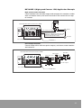
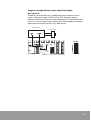
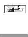
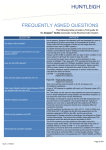
NX70-HSC1 (High-speed Counter 1CH) Application Example
High-speed Counter Function
Count rotation from encoder output and compare the rotation number
with set rotation count, and send instructions like conversion or stop
to inverter.
Inverter
Read data with advanced instruction, READ
Motor
C=P conversion input
C>P stop input
Input the output from rotary encoder
with phase differential input mode
(4 x) of High-speed Counter
Encoder
Set condition with advanced instruction, WRITE
NX70-HSC1
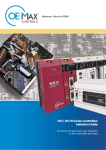
Pulse Output Function
Control motor drive with two pulse outputs, and count motor rotation
and control it.
Read data with advanced instruction, READ
X-Y table
Motor drive
Input positive current
Motor
Input reverse current
Encoder output
Set condition with advanced instruction, WRITE
NX70-HSC1
11
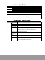
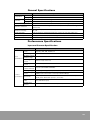
General Specifications
Item
Temperature
Humidity
Specifications
Operating
0 °C to +55 °C (32 °F to 131 °F)
Storage
-25 °C to +70 °C (-13 °F to 158 °F)
Operating
30 to 85% RH (Non-condensing)
Storage
30 to 85% RH (Non-condensing)
Withstand voltage
500V ac for 1 minute between I/O terminal (dc) and frame ground (power unit)
Insulation resistance
100 MΩ or more at 500 mega V DC between I/O terminal (dc) and frame ground
(power unit)
Vibration immunity
10 to 55Hz, 1 cycle/minute: double amplitude of 0.75 mm, 10 minutes on 3 axis
(X,Y, Z)
Shock immunity
Peak acceleration and duration 15g/11 ms, 3 times in each X, Y, Z direction
Noise immunity
1500Vp-p with 50ns to 1µs pulse width (generated by noise simulator)
Ambience
No corrosive gas, no excessive dust
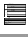
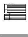
Performance Specifications
Item
Input
specification
Counter
specification
12
Specifications
Number of input
points
6 points (INA, INB, RST, INH, ZERO, SUB)
Input voltage
5 to 12V DC 12 to 24V DC
Allowable voltage
variation range
4.75 to 13.2V DC 10.2 to 26.4V DC
ON
voltage/current
4.5V or less/3 mA or less 9.6V or less/3 mA or less
OFF
voltage/current
1.5V or more/0.6 mA or more 2.5V or more/0.6 mA or more
Number of
counter channels
1 point (UP-DOWN COUNTER)
Counting range
24-bit signed integer (binary format) (-16,777,216 to 16,777,215)
Max. counting
speed
100kcps (Recommended counter input: within 30kcps)
Input mode
3 modes (direction discrimination: Pulse + Direction, individual input:
CW, CCW, phase differential input (1 x, 4 x mode)
Min. input pulse
width
5us (individual input)
Multiplication
function
1 x, 4 x mode (phase differential input mode)
Output Specification
Item
General
Control
Output
Pulse
Output
Specifications
Isolation method
Photo coupler
Output format
Transistor output (NPN, open collector)
Rated use voltage
5 to 24V DC
Allowable voltage
variation range
4.75V to 26.4V DC
Max. load current
50 mA
Residual voltage
0.5V or less
Leakage current
10 uA
Number of output
points
2 points (C=P, C>P)
COMMON
terminal
2 points/COMMON
Fuse
N/A
Response time
OFF -> ON: 10µs or less, ON -> OFF: 100µs or less
Number of output
points
2 points (OUT0, OUT1)
Output frequency
200 to 40 KHz DUTY 50% ±25%, variation ±5%
Low-frequency
200 to 5 KHz
High-frequency
4K to 40 KHz (Min. 36 KHz)
Variation time
100 to 500 ms
Rise/fall time
2us or less
Others
Item
Specifications
Operation indicator
LED
Internal current
consumption (5V)
350 mA
External connection
method
Terminal block (20-pin)
Suitable cable size
0.5 to 1.25 mm2
Terminal block
terminal screw
M3.0 screw
Occupied I/O points
32 points (16R, 16R)
(16 points input, 16 points output)
13
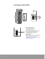
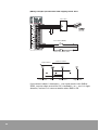
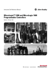
Unit Diagram (NX70-HSC1)
(Bottom)
(Front)
1. Input operation LED
Shows ON/OFF status of I/O.
2. Terminal block (20-pin)
Terminal block for I/O and power wiring.
3. Pulse output adjustment volume
Adjusts pulse output frequency or
conversion time.
(Bottom)
14
4. Mode switch
DIP switch for shifting counter unit function.
Preset as SW1: ON, others OFF (phase
differential input, 4 x mode).
(See "Mode Switch" in Chapter 1, "Mode
Switch" in Chapter 2.)
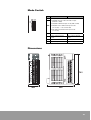
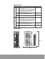
Mode Switch
ON
SW1
OFF
(SW1/SW2)
1. OFF/OFF: Direction discrimination input
(PULSE + SIGN)
2. OFF/ON: Individual input mode (CW + CCW)
SW2
3. ON/OFF: Phase differential input mode
(4 x mode)....... Recommended
4. ON, ON Phase differential input mode
(1 x mode)
SW3
Retentive Output
Non-retentive output
SW4
Pulse output internal
count
Pulse output external
count
SW5
C=P mode
C=0 mode
SW6
1 pulse output
2 pulse output
SW7 and SW8 are not used.
Dimensions
15
16
2
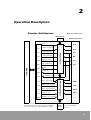
Operation Description
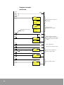
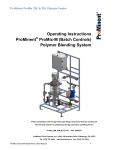
Counter Architecture
When mounted in slot 0
Mode switch
SW1 to 6
External I/O terminal
Reset
IN A
R1.0
R1.1
Current value latch
IN B
Send initial value
Send target value
R1.3
C=P (coincidence)
R0.0
C>P (comparison)
Counter part
R1.2
INH
C=P
C>P
R0.1
CPU Unit
R0.2
RST
Overflow
Underflow
R0.3
C=P (hardware output)
R0.5
Pulse output start
Pulse output selection
R1.5
Pulse output frequency
R1.6
Return to zero
R1.7
Pulse output part
R1.4
ZERO
SUB
OUT 0
OUT 1
Return to zero completed
R0.4
The core of counter consists of counter and pulse out
part, and enables each function based on settings of
mode switch and pulse output adjustment volume.
F.MAX
F.MIN
DELAY
Pulse output setting
volume
17
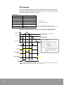
I/O Contact
NX70 PLC High-speed Counter Unit (NX70-HSC1) occupies 16 points
input and 16 points output, totaling 32 points. (Internally, only 6 points
input and 8 points output are used.)
Input Contact
Input Contact
Name
R0.0
C=P (coincidence output)
R0.1
C>P (comparison output)
R0.2
OVER FLOW
R0.3
UNDER FLOW
R0.4
Return to zero completed.
R0.5
C=P (hardware output)
R0.6 to R0.15
Unused
C: Current value
P: Set value (target value)
C=P, C>P output can be external output.
(Specification differs partly based on the mode.)
Relation between internal relay and current value (R0.0 to R0.3)
16777215
Set value can be only positive.
(0 to 16777215)
Set value
Flag Variation
0
-1
C=P (R0.0): ON when current value =
set value.
-16777216
C>P: ON when current value > set value.
OVER FLOW: ON when current value >
16777215
C=P
(R0.0)
UNDER FLOW: ON when current value <
-16777216
C=P (R0.5): Coincide with external output
C=P and output width is 100ms
and retained, based on DIP
switch setting on the bottom of
the unit.
C>P
(R0.1)
OVER FLOW
(R0.2)
UNDER FLOW
(R0.3)
C=P
(R0.5)
NOTE
18
If OVER FLOW/UNDER FLOW occurs two consecutive times, flag variations after
that wiIl be incorrect. So precaution is required.
R0.0 to R0.3
When operating with comparison relay from R0.0 to R0.3, CPU unit
scan time must be considered as below. When scan time is long,
operation will be delayed. Specifically R0.0 [C=P] turns on only when
the current value coincides with target value, so if the ON time is short
it may not be input to CPU unit.
In such cases, connect external output (C=P) to other input unit and
input to CPU unit, or use R0.5 (hardware coincidence output: same as
external output C=P).
R0.4: Return to zero completed flag
Indicated it has arrived at zero in return to zero mode, and retained
until the next return to zero contact (R1.7) turns ON. See "Return to
zero mode" in Chapter 2 for more detail on return to zero mode.
R1.7
(Return to zero start)
R0.4
(Complete)
Complete
Complete
R0.5: Coincidence output flag
Same signal as external output terminal C=P. Either 100 ms ON output
or Retentive output can be selected using the mode switch.
R0.5 output is synchronized with input pulse, so when current value
and target value coincides at zero, like in the case of power input,
output disables. See "SW3, SW5 (Coincidence Output Mode
Selection)" in Chapter 2.
19
Output Contact
Mounted in slot 0
Input Contact
Name
R1.0
Counter reset
R1.1
Counter current value input
R1.2
Counter initial value setting
R1.3
Counter target value (set value) setting
R1.4
Pulse output start
R1.5
Pulse output selection
R1.6
Pulse frequency conversion
R1.7
Return to zero instruction
R1.8 to R1.15
Unused
R1.0: Counter reset
When this relay is ON, the current value and target values are reset (to
zero) and C=P (coincidence output) is also turned OFF. Pulse output is
also turned OFF. This contact operates just like external input (RST).
Counter does not operate when R1.0 contact is ON, so turn it OFF
when counter operation is needed again.
Set value
(target value)
0
C=P
R1.0
20
R1.1: Counter current value input
When this output contact is ON, current value at the counter is stored
in the inside buffer of the counter.
Data READ is executed with transmission instruction. When R1.1 is not
ON and current value is read, the inside buffer of High-speed Counter
is not written so the previous input data will be read.
Counter
Buffer
Instruction
READ
R1.1
CPU unit
High-speed Counter unit
When High-speed Counter (NX70-HSC1) is mounted in slot 0 and counter current
value is sent to W0 and W1
M0.0
R1.1
( )
R
M0.0
OUTR
CH = 1
I/O part refresh (R1.0 to R1.15)
READ
TO = W0 : Input from TO, W0
SZ = 2 : Size, read 2 words.
FR = 0:0 : Shared memory address
0 of slot 0
TO = W0
SZ = 2
FR = 0 : 0
When M0.0 turns ON, R1.1 is turned ON by I/O part refresh and two words of
counter current value (address 0 to 1) are sent to W0 to W1. When outputting
converted current value, turn R1.1 OFF and ON again.
R1.1
Latch
Count value
(Instruction: READ)
Latch
Count value
READ
Count value
READ
Same data can be read.
21
R1.2: Send initial value
R1.3: Send target value
When this output contact turns ON, the data pre-sent to the inside
buffer of High-speed Counter is set as initial and target value (set
value) for counter. When R1.2 to R1.3 are turned ON before the initial
value and target value data are sent to the inside buffer of High-speed
Counter, the previously sent buffer data is set.
R1.3
Counter
Buffer
Instruction
READ
R1.2
CPU unit
High-speed Counter unit
In addition, when R1.2 is turned ON, coincidence output (C=P) turns
OFF at the same time.
Program Example 2)
When High-speed Counter is mounted in slot 0 and set W0 and W1 data as
the initial value of High-speed Counter.
M0.0
TO = 0:2 : Store to slot 0, shared
memory 2
SZ =2
: Read 2 words.
FR =W0 : Specify data to WRITE
(W0)
WRITE
TO = 0 : 2
SZ = 2
FR = WO
M0.1
R
R1.2
( )
(Note) When resetting initial and target values, turn R1.2 and R1.3 OFF
and ON again. They should be turned on for only 1 scan, as shown
above.
R1.4: Pulse output start
When this output contact is ON, pulse is output from the output
terminal decided based on the mode switch on the bottom of the unit
and R1.5 (pulse output selection).
R1.5: Pulse output selection
Decides from which one of OUT0 and OUT1 the pulse from R1.4 (pulse
output start) should be sent out when the mode switch is set to pulse
output 2.
R1.6: Pulse frequency conversion
Outputs pulse with frequency pre-set with volume with converted
high- and low- frequencies.
R1.7: Return to zero
When this output contact is ON, return to zero mode starts.
22
I/O Data (Word)
The set values and current values of the initial and current values from
NX70 PLC High-speed Counter can be read. Each data (course/initial/
objective) consists of 32-bit and is segmented as shown in the table
below. Data I/O is controlled by READ, WRITE instructions in
NX70 series.
Shared memory MAP of High-speed Counter
Instruction
READ
WRITE
Word address
1
1
32-bit
Current value (Lower 16-bit)
Initial value (Lower 16-bit)
Current value (Upper 8-bit
and sign)
Initial value (Upper 8-bit and sign)
2
3
NOTE
32-bit
Target value (Lower 16-bit)
Target value (Upper 8-bit (only
positive sign))
All set to zero during power input.
Current value and initial value have a sign bit at the most significatn bit (MSB), bit
8. So if it is set as " $ FF", it becomes a negative number.
Upper 8-bit
Lower 8-bit
Word address 3
Sign $ 00: (+)
$ FF: (-)
Data
* Target value setting is not accepted as “H FF”.
When writing data as decimal number, do the following:
M0.0
DLET
D = W0
S = -500
Send -500 as 2 words
(32-bit data) to W0 and W1
($ FFFFFE0C in hexadecimal)
WRITE
TO = 0 : 0
SZ = 2
FR = W0
Special unit instruction
(data input)
23
Advanced Instructions
Instruction: READ
Operation condition
Starting number of CPU unit register
where to store read data: W0
READ
TO = W0
R
SZ = 5
Number of words to read: 5 words
FR = 0 : 0
Starting address of shared memory to
read (High-speed Counter memory MAP):
NO.0
Slot number where the special unit (Highspeed Counter unit) to read is mounted:
Slot 0
Instruction: READ
CPU
unit
Data
High-speed
Counter
unit
The program above reads 5 words of data
from shared memory address 0 of Highspeed Counter mounted in slot 0, and
stores the 5 words of data to W0 to W4 of
CPU unit.
Instruction: WRITE
Program example where NX70-HSC1 is mounted in slot 0 and only CH0 is being used.
Slot number where the special unit (Highspeed Counter unit) to write is mounted:
Slot 0
Operation condition
R
WRITE
Starting address of shared memory to
write (High-speed Counter memory MAP):
NO.0
TO = 0 : 0
SZ = 2
FR = W10
Number of words of data to write:
2 words
Starting address of CPU unit register (W)
Instruction: WRITE
CPU
unit
24
Data
High-speed
Counter
unit
The program above writes 2 words of data
from W10 of CPU unit (W10 to W11) to
shared memory addresses 0 to 1 of Highspeed Counter unit.
I/O Terminal
Input Terminal
Counter Input Terminal (INA, INB)
The input terminals of High-speed Counter support 3 input modes: phase
differential input (2-phase input)/direction discrimination input/individual
input. (Set by DIP switch as illustrated below.)
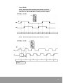
Phase differential input mode (2-phase mode), 4 x mode:
Usually this mode is recommended. (noise countermeasure)
(You must use this mode when counting encoder output)
SW1,2 = ON, OFF
ON OFF
SW1
2
INA
ON
OFF
INB
n
n+1
n+2
n+3
n+4
n+3
n+2
n+1
n
Phase differential input mode (2-phase mode), 1 x mode
SW1,2 = ON, ON
ON
OFF
SW1
2
T
INA
ON
OFF
INB
ta
tb
n
tc
td
n+1
n+2
n+3
n+2
n+1
ta. tb. tc. td ≥ 1/8T
T ≥ 10µs
25
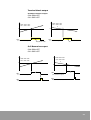
Direction discrimination input mode (Pulse + Direction)
SW1,2 = OFF, OFF
ON
OFF
SW1
2
ta
INA
(Pulse)
tb
tc
td
ON
OFF
INB
(Direction)
n
n+1
n+2
n+1
ta, tb, tc td ≥ 5µs
INA
n
INB
Function
H
Down
L
Up
n-1
* H: ON
L: OPEN(OFF)
Individual input mode (CW + CCW)
SW1,2 = OFF, ON
ON
OFF
SW1
2
ta
tb
* INA: UP
ON
OFF
INB: DOWN
INA
(CW, Up pulse)
INB
(CCW, Down pulse)
n
tc
n+1
ta, tb, tc ≥ 5µs
26
n+2
n+1
n
n-1
Control Input Terminal
Reset input terminal (RST)
Resets course and target values of High-speed Counter (to zero). Turns
OFF when coincidence output (C=P) is on. Specifically, pulse output
also turns OFF. (Operates as same level with Internal contact R1.0 of
High-speed Counter.
RESET ON
OFF
Count
---------
n-1
n
n+1
---
n+m
0
1
C=P
(External output retentive mode)
Counter inhibition input terminal (INH)
When this terminal is ON, input on count input (INA, INB) is not
counted.
INA
INB
Count
ON
OFF
ON
OFF
10
11
12
13
14
27
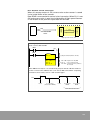
Pulse output control input (ZERO, SUB)
Used as return to zero signal input terminal when controlling motor by
using pulse output (OUT0, OUT1). Converts high-speed pulse to lowspeed when SUB turns ON, and stops pulse output when ZERO is ON.
Pulse output frequency(f)
High-frequency
Low-frequency
R1.7
(Return to zero start)
SUB
(Input before zero)
ZERO
(Zero input)
R 0.4
(Return to zero
completed)
Return to zero start
Pulse output is
decided based on
mode switch setting
and R1.5 (pulse
output selection).
Detection before zero
Converts highfrequency pulse output
to low-frequency.
Zero detection
Stops pulse output
Return to zero
completed signal ON
Retained until the
next R 1.7 turns ON.
NOTE Pulse output does not stop even when ZERO turns ON before SUB turns ON.
28
Output Terminal
Pulse Output (OUT 0, OUT 1)
Pulse output terminal for controlling step motor. Enables temporary
location decision. Output method can be set by mode switch to either
1 pulse output or 2 pulse output.
●
1 pulse output mode (SW6-ON)
●
2 pulse output mode (SW6-OFF)
Pulse output condition: Starts when R1.4 turns ON. (Usual mode)
Starts when R1.7 turns ON. (Return to zero
mode)
Pulse output stop condition: R1.0 turns ON
RST input turns ON
Coincidence output (C=P) turns ON
[C=P output turns on at zero in C=0
mode] See "Chapter 2" for more
details.
Comparison Output (C>P, C=P)
Outputs the comparison between current and target values of counter.
000000
FFFFFF
(16777215)
target value
Values in ( ) are decimal numbers.
Target value must be set as positive.
$000000 to $FFFFFF (0 to 16777215)
Values in ( ) are decimal numbers.
000000
FFFFFF(-1)
000000
FFFFFF
(-16777216)
C=P
C >P
C=P output sets course as zero in C=0 mode.
Output time width can be selected either
100ms or retention. (Same as internal
contact R0.5.)
29
Mode Switch
Mode switch on the bottom of High-speed Counter unit (NX70-HSC1)
determines the following functions. DIP switch consists of 8 switches.
SW7 and SW8 are not used.
ON OFF
SW1
2
3
4
5
6
7
Unused
8
Unused
As default, DIP switches are set as shown on
the right: SW1: ON, and the others are OFF
(phase differential input, 4 x mode).
High-speed Counter unit
(NX70-HSC1) bottom
(Mode switch)
Function of each switch is as follows:
ON
OFF
(SW1/SW2)
1. OFF/OFF: Direction discrimination input (PULSE + SIGN)
SW1
2. OFF/ON: Individual input mode (CW + CCW)
3. ON/OFF: Phase differential input mode (4 x mode):
Recommended (manufacturer default)
SW2
4. ON/ON Phase differential input mode (1 x mode)
SW3
Retentive output
Non-retnetive output
SW4
Pulse output internal count
Pulse output external count
SW5
C=P mode
C=0 mode
SW6
1 pulse output
2 pulse output
* SW7 and SW8 are not used.
30
SW1, 2 (Input mode switch)
Phase differential input mode (2-phase mode), 4 x mode:
Usually this mode is recommended. (noise countermeasure)
(You must use this mode when counting encoder output.)
SW1,2 = ON, OFF
ON
OFF
SW1
2
INA
ON
OFF
INB
n
n+1
n+2
n+3
n+4
n+3
n+2
n+1
n
Phase differential input mode (2-phase mode), 1 x mode
ON OFF
SW1
2
SW1,2 = ON, ON
T
INA
ON
OFF
INB
ta
tb
n
tc
td
n+1
n+2
n+3
n+2
n+1
ta. tb. tc. td ≥ 1/8T
T ≥ 10us
31
Direction discrimination input mode (Pulse + Direction)
ON OFF
SW1,2 = OFF, OFF
ta
SW1
2
tb
tc
td
ON
INA OFF
(Pulse)
INB
(Direction)
n
n+1
n+2
n+1
ta, tb, tc, td ≥ 5µs
INA
n
INB
Function
H
Down
L
Up
n-1
* H: ON
L: OPEN(OFF)
Individual input mode (CW + CCW)
SW1,2 = OFF, ON
ON OFF
SW1
2
ta
tb
* INA: UP
ON
OFF
INB: DOWN
INA
(CW, Up pulse)
INB
(CCW, Down pulse)
n
tc
n+1
ta, tb, tc ≥ 5µs
32
n+2
n+1
n
n-1
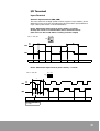
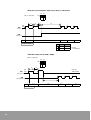
SW3, SW5 (Coincidence Output Mode Selection)
C=P Retentive Output (SW3, SW5 -> ON)
ON OFF
P (target value)
Count value
1
2
3
4
5
6
7
8
C=P output
P
C >P
P +1
RST
Output C=P turns OFF when data is newly set with RST input R1.0 or
counter. When count value and target value coincide, like power input,
C=P output is OFF. (Coincidence output only turns ON when the count
value of pulse count coincides with target value.)
C=P Non-retnetive output (SW3 -> OFF, SW5 -> ON)
P
ON OFF
Count value
1
2
3
4
5
6
7
8
C =P
P
C >P
100 ms ±30%
P +1
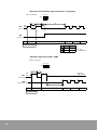
C=0 Retentive Output (SW3 -> ON, SW5 -> OFF)
P
ON OFF
1
2
3
4
5
6
7
8
0
C=P
0
C>P
P
NOTE
Output turns ON when count value is 0 in C=0 mode. C>P output starts according
to target value P.
33
C=0 Non-retentive output (SW3, SW5 -> OFF)
C (Count Value)
ON OFF
1
2
3
4
5
6
7
8
P (Target value)
0
C=P
C>P
100 ms ±30%
P
Even in non-retentive output mode, C=P stops when C=P output 100ms
ends, initializes counter, or RST input or R1.0 turns ON.
C >P
100 ms ±30%
RST
(
R1.0
Execute data setting instruction
)
These C=P, C>P output not only externally, but also to internal relay
(R0.1, R0.5).
34
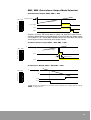
SW6 (Pulse output mode switch)
Switch pulse output to external terminal (OUT0, OUT1) output mode.
1 pulse output mode (SW6-> ON)
ON OFF
1
2
3
4
5
6
7
8
R1.4
(Pulse start)
R1.5
(Direction shift)
OUT 0
OUT 1
2 pulse output mode (SW6 -> OFF)
ON OFF
1
2
3
4
5
6
7
8
R1.4
(Pulse start)
R1.5
(Direction shift)
OUT 0
OUT 1
Pulse frequency from OUT0 and OUT1 is adjusted by external volume.
35
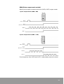
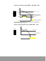
SW4, SW5 (pulse output and count operation)
NX70 PLC High-speed Counter (NX70-HSC1) unit has pulse output
function for temporary location decision. SW4 decides whether to
count pulse output internally or to count external pulse input from
input terminal.
SW5 decides count mode. When using pulse output and external
input, set input frequency to 40KHz or less.
Internal count: Up down mode (SW4.5 -> ON)
Counts pulse output internally. (Do not connect to internal terminal INA
and INB.)
ON OFF
P
Count value
1
2
3
4
5
6
7
8
Pulse output turns OFF when the
value coincides with target value
(C=P output ON).
Up down count
R1.5
C=P
When R1.5 is ON, pulse output varies based on output terminal mode
set by SW6.
External count: Up down mode (SW4 -> OFF, SW5 -> ON)
ON OFF
P
Count value
1
2
3
4
5
6
7
8
C=P
36
Pulse output turns OFF when the
value coincides with target value
(C=P output ON).
Up down count
Internal count: down counter (SW4 -> ON, SW5 -> OFF)
Count value
ON OFF
Always down count.
P
(target
value)
1
2
3
4
5
6
7
8
0
R1.5
When this is ON, pulse
output varies based on
output terminal mode set
by SW6.
C=P
Pulse output turns OFF when
count value (C) turns zero.
Do not connect anything to external terminal INA and INB when
counting pulse output internally.
External count: Up down counter (SW4, SW5 → OFF)
ON OFF
1
2
3
4
5
6
7
8
Up down count
P
0
Pulse output turns OFF when
count value turns zero.
C=P
37
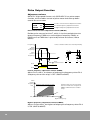
Pulse Output Function
Adjustment volume
NX70 PLC High-speed Counter unit (NX70-HSC1) has pulse output
function, which enables control of pulse motor and slow up down
control for servo motor.
●
●
●
DELAY
F. MIN
F. MAX
c Pulse conversion time adjustment volume
d Lowest frequency adjustment volume
e Highest frequency adjustment volume
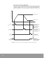
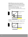
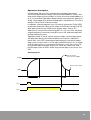
Pulse conversion time adjustment volume (DELAY)
Decides pulse conversion time T, which is the time period when the
lowest frequency F.MIN turns to the highest frequency F.MAX, or
F.MAX turns to F.MIN that is pre-set by volume resistance. (100 to
500ms)
Frequency f
Pulse conversion time does not vary linearly.
F.max
(Highest
frequency)
t1 t2
f2
F.min
(Lowest
frequency)
f1
t (time)
T
R1.4
f3
f4
t4
t
Pulse
conversion time
R1.6
t3
f1
f2
> t
2
t1
f3
f
> 4
t3
t4
ON
OFF
Lowest frequency adjustment volume (F.MIN)
Adjust F.min, that is, the lowest of output pulse frequency when R1.6
(frequency conversion relay) is OFF. (200HZ to 5kHZ)
F.min
(Lowest
frequency)
kHz
Variation range of F.min vs F.min
Variation range of F.min is decided
based on F.max. Part of range from
200Hz to 5kHz will be the variation
range.
5
4
3
2
0.7
1
0.2
4
10
20
30
40
kHz
F.max
(Highest frequency)
Highest frequency adjustment volume (F.MAX)
Adjusts F.max, that is, the highest of output pulse frequency when R1.6
is ON. (4kHZ to 40kHZ)
38
Pulse output description
OUT 0, OUT 1
(Pulse output)
R1.4
(Pulse start)
Coincidence
output (C=P)
C
P
Pulse output starts at OUT0 and OUT1 terminals when R1.4 (pulse
start) turns ON. Output pulse number is monitored by counting output
pulse with counter settings. (Count method will be described later in
“Frequency Temporary Measurement Program” section.) Pulse output
turns OFF when coincidence output is OFF. R1.5 (pulse output selection
replay) decides which one of OUT0 or OUT1 will be used for pulse
output. To force pulse to OFF during pulse output, use RST input or
turn R1.0 to ON.
f2
f1
* f1: Lowest frequency
f2: Highest frequency
OUT 0
T
R1.4
R1.6
(Frequency
conversion)
C=P
When R1.6 (frequency conversion relay) contact is OFF, low-frequency
pulse output starts. Turn it ON to output high-frequency pulse. Pre-set
with each volume the following values: F.min, F.max, F.min <--> F.max
conversion time T. (See "Adjustment volume" in Chapter 2.)
39
Setting
Adjust volume as follows, using minus driver.
●
Set CPU unit to program mode (PROG.).
●
With WinGPC S/W force I/O function, turn R1.7 ON and pulse output
starts. (SUB input: OFF)
(When High-speed Counter unit is mounted in slot 0)
●
Adjust volume (F.max) while viewing OUT0 waveform on
oscilloscope.
●
Turn SUB input ON and adjust volume (F.min) as above.
●
Conversion time T must be set to the most suitable value by
actually operating motor.
NX70 High-speed Counter (NX70-HSC1)
Oscilloscope
Delay
F.min
F.max
Switch
(Bottom)
(Front)
Temporary use example (Frequency temporary
measurement program)
Temporarily measure the frequency of pulse output without devices
like oscilloscope. The program below monitors frequency every
second, so pulse output frequency can be easily set with this method.
(In the example below, High-speed Counter unit is mounted in slot 0.)
40
Programming
WinGPC S/W
F1.0
F
Mode Switch
DLET
D = W20
ON OFF
S = 99999
WRITE
TO = 0 : 2
SZ = 2
FR = W20
F1.0
F
F1.0
F
Target value setting
R1.3
( )
1
2
3
4
5
6
7
8
Set target value
IINPR
CH = 0
I/O refresh
OUTR
CH = 1
F1.4
R
R1.4
( )
(Pulse start)
R1.1
( )
F1.4
R
Current value latch
IINPR
CH = 0
OUTR
CH = 1
READ
TO = W0
SZ = 2
FR = 0 : 0
Read current value every second
DLET
D = W10
S=0
NX70-HSC1
WRITE
TO = 0 : 0
SZ = 2
FR = W10
R1.1
R
R1.1
R
Reset to zero every second
R12
( )
Initial value
IINPR
CH = 0
OUTR
CH = 1
41
Operation Description
To monitor current value data every second, values similar to output
frequency are stored in data register DT0 and DT1.
Data register monitoring is controlled by programming tool, WinGPC.
The example on the previous page outputs lowest frequency F.min.
When setting highest frequency F.max, R1.6 must be turned ON by
forced output adjustment in RUN mode. (Force I/O adjustment can be
done by programming S/W.)
Pulse output start, stop condition
●
Start (start output)
1. R1.4 (pulse start) is ON.
Pulse is not output when current value coincides with target
value.
2. R1.7 (return to zero start) is ON. See"Return to zero mode" in
Chapter 2 for more details.
●
Stop (stop output) condition
1. Coincidence output (C=P terminal output) is ON
(In C=P mode, current value coincides with target value
In C=0 mode, current value is zero.)
2. RST input is ON.
3. R1.0 (reset) contact is ON.
4. In return to zero mode, ZERO input turns ON after SUB input
turns ON. See "Return to zero mode" in Chapter 2 for more detail.
42
Return to zero mode
NX70 PLC High-speed Counter (NX70-HSC1) 1CH unit has temporary
location decision function for controlling motor with pulse output. In
return to zero mode, the following I/O is available.
●
R1.7 (Internal contact)
Starting signal of return to zero. If this is ON, this mode is pre-set by
mode switch and R1.5 (pulse output selection relay), and pulse
output starts from OUT0 or OUT1. Output frequency is set to highfrequency (F.max). Set R1.7 to turn only 1 scan ON during program
operation.
●
SUB input
When this is ON, output frequency shift from high-frequency
(F.max) to low frequency (F.min).
●
ZERO input
When this in ON, low-frequency (F.min) output turns OFF.
(ZERO input is recognized only after SUB input is ON.)
●
R0.4 (internal contact)
Complete signal of return to zero. R0.4 turns ON when zero input
turns ON. This contact is retained until return to zero operation
starts. When return to zero completes, counter current value is set
to undefined, so new data must be defined before the next
operation starts.
High-frequency
(F.max)
Low-frequency
(F.min)
t
R1.7
SUB
ZERO
R0.4
43
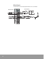
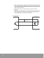
Wiring Diagram
The internal I/O circuit of High-speed Counter unit is as follows:
Internal wiring
External wiring
Load
44
[Wiring example 1] Connection with servo drive
Servo drive
Zero switch (ZERO)
Before zero switch (SUB)
Reverse rotation
Right rotation
Lowest limit
Zero
Before zero
Highest limit
If the control subject is located at ⓐ , the signal passes from SUB to
ZERO, so pulse stops at zero. But if it is located at ⓑ or ⓒ, turn it in right
direction, and turn it in reverse rotation when SUB is ON.
45
[Wiring example 2] Connection with stepping motor drive
Servo drive
Zero switch (ZERO)
Before zero switch (SUB)
Reverse rotation
Right rotation
Lowest limit
Zero
Before zero
Highest limit
If the control subject is located at ⓐ , the signal passes from SUB to
ZERO, so pulse stops at zero. But if it is located at ⓑ or ⓒ, turn it in right
direction, and turn it in reverse rotation when SUB is ON.
46
Program example (Pulse motor control example)
Wiring Diagram:
Temporary location decision is enabled with pulse motor or servo
motor using pulse output (OUT0, OUT1). This example shows a
program that rotates the pulse motor 100,000 pulses in both directions
in turn. It is set to slower motor rotation from high-speed to low-speed
when the pulse output remains only 3000 pulses.
Motor drive
Pulse motor
HighDC IN
speed
Counter 16points
Mode switch
NX70 High-speed Counter (NX70-HSC1)
47
Program example
WinGPC S/W
F1.0
M0.0
(
F
)
TC0
DLET
D = W0
S = 3000
M0.0
Set low-speed conversion
point data
WRITE
TO = 0 : 2
SZ = 2
FR = W0
DLET
D = W5
S = 100000
Program to turn only 1
scan ON
Set total move
(output pulse number)
WRITE
TO = 0 : 0
SZ = 2
FR = W5
M0.0
R1.2
(
R
)
R1.3
(
M0.0
)
INPR
CH = 0
OURT
CH = 1
R1.3
R0.1
R2.0
R
R1.4
(
)
Pulse output start
R1.6
(
)
Low-speed conversion relay
R1.5
Conversion of right and
reverse rotation shift
INC
D = W1
Input for coincidence output
M1.0
(
R2.0
48
)
TIM
T CH = 0
SV = 10
R1.1
R1.1
Set the target value (lowspeed conversion point) and
initial value (total move) with
counter.
R1.1
(
)
READ
TO = W10
SZ = 2
FR = 0 : 0
Current value output
Operation description
In RUN mode, R0 turns ON, and each 32 bit of both low-speed
conversion point data as target value area (word address 2 to 3), and
total move (output pulse number) as initial value area (word address 0
to 1) is transmitted. (But High-speed Counter unit processes data bit in
24 bit, so the upper 8 bit of transmitted data is not effective.) Turn R1.2
and R1.3 ON to set to internal counter.
In addition, internal program uses I/O refresh instruction (F143, IORF)
to promote execution. Start pulse output at OUT0 by turning R1.4 ON
after data set to counter. When pulse output starts, course (C) >
objective (P) so internal contact relay R0.1 (C > P) turns ON, and pulse
output frequency conversion relay R1.6 turns ON, and the output will
be high-frequency pulse.
Operation mode is set to internal counter mode, so the output pulse
will be automatically counted and when course pulse < objective
pulse, R0.1 turns OFF converted to low-frequency, and pulse output
stops when current value = 0. The High-speed Counter is in C=0 mode
so C=P output exists, so increment instruction is sent, R1.0 turns ON,
R1.5(pulse output selection relay) turns ON at the same time, and
pulse output starts at OUT1 when next pulse output is set (timer T0 is
ON).
Timing Diagram
R1.6 (C>P) OFF
(Current value<3000)
F. MAX
(Current value (C)=0
F. MIN
DELAY
DELAY
R1.4
R1.6
49
50
3
Specifications and Components
100Kcps fast response High-speed Counter. Easy to monitor and set
data of counter values.
Two counter input channels on one unit.
High-speed Counter Unit Features
NX70 High-speed Counter Unit
NX70-HSC2: 2CH Unit
NOTE
There is no pulse output function for 2CH type (NX70-HSC2) product
1. 100kcps High-Speed Response
High-speed response of 100kcps enables high-accuracy speed
control.
2. Various Input Modes
Phase differential input mode (1 x, 4 x mode) that can count twophase pulse of rotary encoder, individual input mode, and direction
discrimination input mode are provided (set by DIP switch on the
bottom of the unit).
3. Wide Counting Range
Counting range, formatted as 24-bit signed (binary) integer, covers
from -16,777,216 to 16,777,215.
4. Easy to Monitor Counter Measurement and Set Data
Built-in shared memory helps data read/write at PLC freely.
5. Comparison output and coincidence output
Can be used as slow-down or stop signal for controlling motor.
51
[Ex.] Counts rotation from encoder output and compares the rotation
number with rotation count set, and sends instructions like conversion
or stop to inverter.
Inverter
Read data with advanced instruction, READ
C=P conversion input
C>P stop input
Input the output from encoder in
phase differential input mode (4 x
mode) of High-speed Counter
Set condition with advanced instruction, WRITE
NX70-HSC2
52
Motor
Encoder
General Specifications
Item
Temperature
Humidity
Specifications
Operating
0 °C to +55 °C (32 °F to 131 °F)
Storage
-25 °C to +70 °C (-13 °F to 158 °F)
Operating
30 to 85% RH (Non-condensing)
Storage
30 to 85% RH (Non-condensing)
Withstand voltage
500V ac for 1 minute between I/O terminal (dc) and frame ground (power unit)
Insulation resistance
100 MΩ or more at 500 mega V DC between I/O terminal (dc) and frame ground
(power unit)
Vibration immunity
10 to 55Hz, 1 cycle/minute: double amplitude of 0.75mm, 10 minutes on 3 axis
(X, Y, Z)
Shock immunity
Peak acceleration and duration 15g/11ms, 3 times in each X, Y, Z direction
Noise immunity
1500Vp-p with 50ns to 1µs pulse width (generated by noise simulator)
Ambience
No corrosive gas, no excessive dust
Performance Specifications
Input and Counter Specification
Item
Input
specification
Counter
specification
Specifications
Number of input
points
6 points, (INA, INB, PR/INH) x 2
Input voltage
5 to 24V DC
Allowable voltage
variation range
4.75 to 25.0V DC
ON voltage/
current
4.5V or less/3 mA or less
OFF voltage/
current
1.5V or more/0.6 mA or more
Number of
counter channels
2 points (UP-DOWN COUNTER)
Counting range
24-bit signed integer (binary format) (-16,777,216 to 16,777,215)
Max. counting
speed
100kcps (Recommended counter input: within 30kcps)
Input mode
3 modes (direction discrimination: Pulse + Direction, individual input: CW,
CCW, phase differential input (1 x, 4 x mode)
Min. input pulse
width
5us (individual input)
Multiplication
function
1 x, 4 x mode (phase differential input mode)
53
Output Specification
Item
General
Control
output
Specifications
Isolation method
Photo coupler
Output format
Transistor output (NPN, open collector)
Rated use voltage
5 to 24V DC
Allowable voltage
variation range
4.75V to 25V DC
Max. load current
100 mA
Residual voltage
0.5V or less
Leakage current
10 uA
Number of output
points
4 points (C=P, C>P) x 2
COMMON
terminal
2 points/COMMON
Fuse
N/A
Response time
OFF -> ON: 10us or less, ON -> OFF: 100us or less
Others
Item
54
Specifications
Operation indicator
LED
Internal current
consumption (5V)
400 mA
External connection
method
Terminal block (20-pin)
Suitable cable size
0.5 to 1.25mm2
Terminal block terminal
screw
M3.0 screw
Occupied I/O points
32 points (16R, 16R) (16 points input, 16 points output)
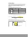
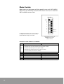
Unit Diagram (NX70-HSC2)
1. Input operation LED
Shows ON/OFF status of I/O.
2. Terminal block (20-pin)
Terminal block for I/O and power
wiring.
3. Mode switch
DIP switch for shifting counter unit
function. Preset as SW1: ON, SW5: ON,
others OFF (phase differential input,
4 x mode). (See "Mode Switch" in
Chapter 3, "Mode Switch" in Chapter 4)
(Front)
LED indicator
ON OFF
SW1
2
3
4
5
6
7
8
CH0
③
LED
Description
=
Current value=Set value or current
value=0 (R0.5)
>
Current value>Set value (R0.1)
A
INA input
B
INB input
P
Preset setting indication
I
Counter inhibition operation
indicator (Inhibit)
=
Current value=Set value or current
value=0 (R0.13)
>
Current value>Set value (R0.9)
(Bottom)
CH1
A
INA input
B
INB input
P
Preset setting indication
I
Counter inhibition operation
indicator (Inhibit)
55
Mode Switch
Switch
SW1
SW2
CH0
Description
SW1,2 =OFF,OFF: Direction discrimination input
(Pulse+Direction)
SW1,2 =OFF,ON: Individual input mode (CW+CCW)
SW1,2 =ON,OFF: Phase differential input mode
(2-phase mode), 4 x mode (Recommended)
SW1,2 =ON,ON: Phase differential input mode
(2-phase mode), 1 x mode
SW3
C=P terminal block output method selection
OFF: one short, ON: retentive output
SW4
C=P terminal block output selection
OFF: current value=set value, ON: current value=0
SW5
SW6
CH1
Non-retnetive
output time is
100 ms ±30%
SW5,6 =OFF,OFF: Direction discrimination input
(Pulse+Direction)
SW5,6 =OFF,ON: Individual input mode (CW+CCW)
SW5,6 =ON,OFF: Phase differential input mode
(2-phase mode), 4 x mode (Recommended)
SW5,6 =ON,ON: Phase differential input mode
(2-phase mode), 1 x mode
SW7
C=P terminal block output method selection
OFF: One short, ON: Retentive output
SW8
C=P terminal block output selection
OFF: When current value = set value, ON:
When current value=0
Dimensions
56
Remarks
Non-retnetive
output time is
100 ms ±30%
4
Operation Description
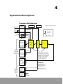
Counter Architecture
C=P TR Out
Terminal
block
Input/Output
Mode switch
LED
(When mounted in slot 0)
C>P TR Out
I NA
Rise edge
operation
I NB
Preset
PR/INH
Level
operation
Inhibit
R1.6~7, R1.14~15
Shared memory
R1.2,
R1.10
Address0,1(CH0)
4,5(CH1)
Preset
Write Only
Current
value (C)
24bit
Counter
Comparer
Initial value
(IV)
Set value (P)
Shared memory
Shared
memory
(Use READ,
WRITE
instructions)
Current
value
R1.1,R1.9
Address0,1(CH0)
4,5(CH1)
Update
Read Only
Shared memory
Set value
Buffer
R1.3,R1.11
Address 2,3(CH0)
6,7(CH1)
Write Only
Set
I/O contact
16 points
input
16 points
output
Input
Contact
ATTNETION
Ch0 I/O contact
Input: R0.0 to R0.7
Output: R1.0 to R1.7
(
(
(
R0.0 to 7,
R0.8 to 15
Output
contact
R1.0 to7,
R1.8 to 15
Cannot read/write directly.
Current value can be read
through current value buffer
and set value can be written
through set value buffer.
For that, output contact
must be controlled.
Ch1 I/O contact
Input: R0.8 to R0.15
Output: R1.8 to 1.15
(
(
(
57
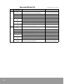
Terminal Block I/O
Terminal block
indication
CH0
Current value=Set value or current value=0,
One short/retentive output setting available.
TR output maximum 100 mA
C>P
Current value >Set value
TR output maximum 100 mA
+
5 to 24 V DC, TR output power
-
0V DC, TR output power
INA+
INA-
INA+ input
INB+
INB-
INB+ input
INA- input
INB- input
Inhibition Function when R1.6=ON
Preset Function when R1.7=ON
Preset Function
(Initial value Current value)
C=P
Current value=Set value or current value=0
One short/retentive output setting available
TR output maximum 100 mA
C>P
Current value > Set value
TR output maximum 100 mA
PR/INH-
+
5 to 24V DC, TR output power
-
0V DC, for TR output power
INA+
INA-
INA+ input
INB+
INB-
INB+ input
PR/INH+
PR/INH-
58
Remarks
C=P
PR/INH+
CH1
Description
C: Current value, P: Set value
INA- input
INB - input
Inhibition Function when R1.14=ON
Preset Function when R1.15=ON
Preset Function
(Initial value current value)
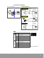
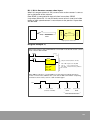
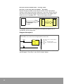
Terminal Block I/O Wiring
C = P, C > P output
Internal Circuit
INA, INB, PR/INH input
External Circuit
Open C oll ecto r
External Power High-speed
5 to 24V DC
counter, 2CH
Pulse Generator
Maximum 100mA
C=P
DC- DC+
+
OUT
L O AD
C>P
-
-
+
DC-
DC+
High-speed
counter, 2CH
Vol tage Outp ut
Pulse Generator
+
OU
T
-
High-speed
counter, 2CH
Lin e Dri ver
Pulse Generator
OUT+
+
OUT-
-
LED
LED
CH1
=
Current value=Set value or current
value=0 (R0.5)
>
Current value>Set value (R0.1)
A
INA input
B
INB input
P
Preset setting indication
I
Inhibit indication
=
Current value=Set value or current
value=0 (R 0.13)
>
Current value>Set value (R0.9)
A
INA input
B
INB input
P
Preset setting indication
I
Inhibit indication
HSC
CH0
NX70-HSC2
Description
=>ABPI
=> ABPI
When "=" sign on LED appears,
refer to mode switch.
59
I/O Contact
High-Speed Counter Unit 2CH(NX70-HSC2) occupies 16 points input
and 16 points output, totaling 32 points.
This manual describes CH0 use. For CH1, set to suitable contact
addresses.
Input contact
Input contact
address
CH0
CH1
Description
Remarks
R0.0
Current value=Set value
(C=P)
Comparer output
R0.1
Current value>Set value
(C>P)
Comparer output, same with C>P terminal block
TR output
R0.2
Overflow
Comparer output
R0.3
Underflow
Comparer output
R0.4
Current value=0 (C=0)
Comparer output
R0.5
C=P hardware output
Same with C=P terminal block TR output
R0.6
PR/INH input
Same with PR/INH terminal block input
R0.7
Retentive PR/INH input
PR/INH terminal block input is set during rise edge.
R0.8
Current value=Set value
(C=P)
Comparer output
R0.9
Current value>Set value
(C>P)
Comparer output, same with C>P terminal block
TR output
R0.10
Overflow
Comparer output
R0.11
Underflow
Comparer output
R0.12
Current value=0 (C=0)
Comparer output
R0.13
C=P hardware output
Same with C=P terminal block TR output
R0.14
PR/INH input
Same with PR/INH terminal block input
R0.15
Similar PR/INH input
PR/INH terminal block input is set during rise edge.
●
R0.0 to R0.4, R0.8 to R0.12: Comparer flag
When operating with comparison relay from R0.0 to R0.4, CPU unit
scan time must be considered as below. When scan time is long,
operation will be delayed. Specifically R0.0 [C=P] turns on only
when the current value coincides with target value, so if the ON
time is short it may not be input to CPU unit. In such cases, connect
external output (C=P) to other input unit and input to CPU unit, or
use R0.5 (same with terminal block output C=P).
●
R0.5, R0.13: Coincidence output flag
Same signal as external output terminal C=P. Either 100 ms ON
output or Retentive output can be selected using the mode switch.
R0.5 output is synchronized with input pulse, so when course and
target value coincides at zero, like in the case of power input, output
is disabled.
60
●
R0.6, R0.14: Same with PR/INH terminal block input
●
R0.7, R0.15: Retained as latched during rise edge of PR/INH
terminal block input.
Relation between internal contact relay and current value
R0.0 to R0.4
(Description below applies to CH0. For CH1, see the previous page for
CH1 contact relay number.)
Current value (CV)
16777215
Set value (P): Set value can be only
positive. (0 to 16777215)
Current value (C):
(-16,777,216 to 16777215)
Set value (P)
0
-16777216
C=P
(R0.0)
C>P
(R0.1)
OVER FLOW
(R0.2)
UNDER FLOW
(R0.3)
C=0
(R0.4)
C=P
(R0.5)
CH0: SW4 =OFF
CH1: SW8 =OFF
* Same with C=P
terminal block
output.
CH0: SW3 = OFF
SW4 = ON
CH1: SW7 = OFF
SW8 = ON
For one short, 100ms ±30%
61
Output contact
Output contact
address
Description
Operation
Remarks
R1.0
Counter initialization
Level
operation
R1.1
Current value buffer update
(Current value → Current value
buffer)
Rise edge
R1.2
Preset (Initial value → Current value)
Rise edge
R1.3
Set value
(Set value buffer → Set value)
Rise edge
R1.4
Ring counter
Level
operation
(If current value=set value)
Initial value → Current value
R1.5
Retentive remove R0.5, R0.7
Rise edge
Remove retentive flag of input
contact
R1.6
Use inhibition function
Level
operation
When terminal block input is
set to PR/INH, counter is set to
count inhibition.
The current value is set to the
initial value (i.e., presetting
occurs) on the rising edge of
the terminal block input PR/
INH.
CH0
R1.7
Use preset function
Level
operation
R1.8
Counter initialization
Level
operation
R1.9
Current value buffer update
Rise edge
(Current value → current value buffer)
R1.10
Preset
(Initial value → Current value)
Rise edge
R1.11
Set value
(Set value buffer → Set value)
Rise edge
R1.12
Ring counter
Level
operation
R1.13
Retentive remove R0.13, R0.15
Rise edge
Remove retentive flag of input
contact
R1.14
Use inhibition function
Level
operation
When terminal block input is
set to PR/INH, counter is set to
count inhibition.
Level
operation
The current value is set to the
initial value (i.e., presetting
occurs) on the rising edge of
the terminal block input PR/
INH.
CH1
R1.15
Use preset function
(If current value=set value)
Initial value →Current value
R1.0, R1.8: Counter initialization
Initialize inside of high-speed counter. Counter does not operate when
R1.0 contact is ON, so turn it OFF when counter operation is needed
again.
62
R1.1, R1.9: Counter current value input
When this output contact is ON, current value at the counter is sent to
the inside buffer of the counter.
Data READ is executed with transmission instruction. (READ
instruction) When R1.1 is not ON and current value is read, the inside
buffer of high-speed counter is not written so the previous input data
will be read.
Counter
Buffer
Instruction
READ
R1.7
CPU unit
High-speed counter unit
Program Example 1)
When high-speed counter (NX70-HSC2) is mounted in slot 0 and counter current
value is sent to W0 and W1
M0.0
R1.1
(
R
M0.0
)
OUTR
CH = 1
I/O part refresh (R1.0 to R1.15)
TO = W0 : Input from TO, W0
SZ = 2 : Size, read 2 words.
FR = 0:0 : Shared memory address
0 of slot 0
READ
TO = W0
SZ = 2
FR = 0:0
When M0.0 is ON, R1.1 is turned ON by I/O part refresh and two words of
counter current value (address 0 to 1) are sent to W0 to W1. When outputting
converted current value, turn R1.1 OFF and ON again.
R1.1
Latch
Count value
(Instruction: READ)
Latch
Count value
READ
Count value
READ
Same data can be read.
63
R1.2, R1.10: Preset (Initial value → Current value)
R1.3, R1.11: Set value (Set value buffer → Set value)
By transferring the data in the internal buffer of the high-speed
counter which were received in advance, it sets the curtent value to
the initial value and the target value to the value in the target value
buffer on the rising edge (OFF → ON) of the output contact.
R1.3
Counter
Buffer
Instruction
WRITE
R1.2
CPU unit
High-speed counter unit
In addition, when R1.2 is turned ON, coincidence output (C=P) is
turned OFF at the same time.
Program Example 2)
When high-speed counter (NX70-HSC2) is mounted in slot 0 and set W0
and W1 data as the initial value of high-speed counter CH0.
M0.0
R
M0.1
R
TO = 0:2 : Store to slot 0, shared
memory 2
SZ =2
: Reads 2 words.
FR =W0 : Specify data to WRITE
(W0)
WRITE
TO = 0:2
SZ = 2
FR = 0:0
R1.2
(
)
(Note) When resetting initial and target values, turn R1.2 and R1.3 OFF
and ON again. Turn only 1 scan ON as shown above.
64
R1.4, R1.12: Ring counter
When R1.4 output contact is ON and current value coincides with set
value, the initial value is automatically sent to current value.
Set value (PV)
Current value (CV)
Initial value (IV)
0
R1.5, R1.13: Retentive Remove
The values retained at R0.5 and R0.7 will be cleared on the rising edge
(OFF → ON) of the output contact R1.5.
R1.6, R1.14: Use counter inhibition function
R1.7, R1.15: Use preset function
Set external input PR/INH of terminal block to counter inhibition and
preset.
Only counter inhibition function
CH0: R1.6 = ON
R1.7 = OFF
Setting
INA
1. SW1, 2 = OFF, ON (Individual
input mode)
2. INB external input = OFF
PR/INH
3. R1.3 (Set value) setting = OFF
Initial value
Current value
Current value
buffer
Operation description
50
0
1
2
3
4
5
When R1.6 =ON, external terminal
block input PR/INH input is used for
counter inhibition so count
disabled for PR/INH input range.
0
R0.6
Same with PR/INH terminal block input
R0.7
Retained latched during rise edge of PR/
INH terminal input rise edge, and cleared
using R1.5 (Retentive removed).
R1.5
65
Only preset function
CH0: R1.6 = OFF
R1.7 = ON
INA
What is preset?
Preset means initial value sent to
current value by external input or
contact control.
PR/INH
50
Initial value
Setting
Current value
0
1
2
3
51 52 53 54 55 56 57
50
4. SW1, 2 = OFF, ON (Individual
input mode)
5. INB external input = OFF
6. R1.3 (Set value setting) = OFF
Current value
buffer
0
Operation description
R0.6
R0.7
R1.5
66
When R1.7=ON, external terminal
block input PR/INH is used for
preset function, and initial value is
sent to current value and counted
during rise edge of PR/NH input
rise edge.
Counter inhibition and preset functions
CH0: R1.6 = ON
R1.7 = ON
INA
setting
PR/INH
Initial value
Current value
Current value
buffer
SW1,2 = OFF, ON (Individual input
mode)
INB external input = OFF
50
0
1
2
0
R0.6
R0.7
R1.5
3
51 52
50
3
Operation description
When R1.6 =ON and R1.7 =ON,
external terminal input "PR/INH" is
used both for counter inhibition
and preset, and initial value is sent
to current value during rise edge of
external terminal "PR/INH" input
rise edge and is not counted in
ranges where PR/INH input is ON.
When PR/INH is input in ranges
where R1.3 is ON, the current value
at the time is automatically sent to
current value buffer.
R1.3
ATTENTION
• When R1.3 is ON, current value is sent to current
value buffer during rise edge of PR/INH input
regardless of use of counter inhibition or preset
function. With this function, you can read counter
value until high-speed external sensor is input. R1.3
can be used for sending set value.
• R0.6 operates as same with external input PR/INH.
• R0.7 is retained as latched on rise edge of PR/INH
regardless of use of counter inhibition or preset
function, and can be cleared by using R1.5 (Retentive
removed).
• Current value buffer update, current value → current
value buffer
: Rise edge of R1.1 rise edge
: R1.3 =ON and rise edge of PR/INH terminal block
input
• Set value buffer → set value transmission: Rise edge
of R1.3
• Initial value → Current value (preset) transmission:
Rise edge of R1.2
: When R1.7 =ON, rise edge of PR/INH rise edge
: R1.4 =ON and current value coincides with set value
• Clear R0.5: Sending set value by rise edge of R1.3
rise edge
: Removing retentive by rise edge of R1.5
rise edge
67
I/O Data (Word)
NX70 PLC High-Speed Counter 2CH (NX70-HSC2) can READ initial
value, set value buffer and current value for CPU unit. Each data
(current value buffer initial value, set value buffer) consists of 32-bit
and is segmented as shown in the table below. Data I/O is controlled
by READ, WRITE instructions.
Shared memory MAP of high-speed counter
Instruction
Word address
CH0
CH1
READ
WRITE
0
Current value buffer (Lower 16-bit) Initial value (Lower 16-bit)
1
Current value buffer (Upper 8-bit
and sign)
Remarks
Initial value (Upper 8-bit and sign)
2
------
Set value buffer (Lower 16-bit)
3
------
Set value buffer (Upper 8-bit (only
positive sign))
4
Current value buffer (Lower 16-bit) Initial value (Lower 16-bit)
5
Current value buffer (Upper 8-bit
and sign)
Initial value (Upper 8-bit and sign)
6
------
Set value buffer (Lower 16-bit)
7
------
Set value buffer (Upper 8-bit (only
positive sign))
Data configuration
Current value buffer
Sign
Current value buffer (Upper 8-bit)
Current value buffer (Lower 16-bit)
Initial value
Sign
Initial value (Upper 8-bit)
Initial value (Lower 16-bit)
0
Set value buffer (Upper 8-bit)
Set value buffer (Lower 16-bit)
Set value buffer
24 Bit
* For set value buffer, "$ FF" value cannot be used for MSB 8-bit.
Data Range
(Hex is indicated with $ mark before numbers.)
Current value, current value buffer: -16,777,216 to 16,777,215
($FF000000 to $00FFFFFF)
Initial value: -16,777,216 to 16,777,215 ($FF000000 to $00FFFFFF)
Set value, set value buffer: 0 to 16,777,215 ($00000000 to $00FFFFFF)
68
Advanced Instructions
Instruction: READ
Program example where NX70-HSC2 is mounted in slot 0 and only CH0 is being used.
Operation condition
Starting number of CPU unit register
where to store read data: W0
READ
R
TO = W0
SZ = 5
Number of words to read: 5 words
FR = 0 : 0
Starting address of shared memory to
read (high-speed counter memory MAP):
NO.1
Slot number where the special unit (highspeed counter unit) to read is mounted:
Slot 0
Instruction: READ
CPU
unit
Data
High-speed
counter
unit
The program above reads 5 words of data
from shared memory address 0 of highspeed counter unit mounted in slot 0, and
stores the 5 words of data to WR0 to WR4
of CPU unit.
Instruction: WRITE
Program example where NX70-HSC2 is mounted in slot 0 and only CH0 is being used
Slot number where the special unit (highspeed counter unit) to write is mounted:
Slot 0
Operation condition
WRITE
Starting address of shared memory to
write (high-speed counter memory MAP):
NO.1
TO = 0 : 0
SZ = 2
FR = W10
Number of words of data to write:
2 words
Source data: Starting address of CPU unit
register (W)
Instruction: WRITE
CPU
unit
Data
High-speed
counter
unit
The program above writes 2 words of data
from W10 of CPU unit (W10 to W11) to
shared memory address 0 to 1 of highspeed counter unit mounted in slot 0.
69
Mode Switch
Mode switch on the bottom of high-speed counter unit (NX70-HSC2)
determines the following functions. DIP switch consists of 8 switches.
SW7 and SW8 are not used.
ON
OFF
SW1
2
3
4
5
6
7
8
As default, DIP switch is set as SW1: ON, SW5: ON
and the others are OFF (phase differential input,
4 x mode) as shown on the right.
High-speed counter unit
(NX70-HSC2) bottom
(Mode switch)
Function of each switch is as follows:
Switch
SW1
SW2
SW1,2 =OFF,OFF: Direction discrimination input (Pulse + Direction)
SW1,2 =OFF,ON: Individual input mode (CW+CCW)
SW1, 2 =ON, OFF: Phase differential input mode (2 phase
mode), 4 x mode (Recommended)
SW1,2 =ON,ON: Phase differential input mode (2-phase mode),
1 x mode
SW3
C=P terminal block output method selection
OFF: one short, ON: retentive output
SW4
C=P terminal block output selection
OFF: current value=set value, ON: current value=0
SW5
SW6
SW5,6 =OFF,OFF: Direction discrimination input (Pulse + Direction)
SW5,6 =OFF,ON: Individual input mode (CW+CCW)
SW5,6 =ON,OFF: Phase differential input mode (2 phase mode),
4 x mode (Recommended)
SW5,6 =ON,ON: Phase differential input mode (2-phase mode),
1 x mode
SW7
C=P terminal block output method selection
OFF: One short, ON: retentive output
SW8
C=P terminal block output selection
OFF: ON when current value = set value, ON: When current value=0
CH0
CH1
70
Description
Remarks
Non-retnetive
output time is
100 ms ±30%
Non-retnetive
output time is
100 ms ±30%
Input Mode
Phase differential input mode (2-phase mode), 4 x mode:
Usually this mode is recommended. (noise countermeasure)
(You must use this mode when counting encoder output.)
CH0: SW1, 2 = ON, OFF
CH1: SW5, 6 = ON, OFF
ON OFF
SW 1
2
3
4
5
6
7
8
ON
OFF
INA
INB
n
n+1
n+2
n+3
n+4
n+3
n+2
n+1
n
Phase differential input mode (2-phase mode), 1 x mode
CH0: SW1, 2 = ON, ON
CH1: SW5, 6 = ON, ON
ON
OFF
ON OFF
SW 1
2
3
4
5
6
7
8
T
INA
INB
ta
tb
n
tc
td
n+1
n+2
n+3
n+2
n+1
ta. tb. tc. td ≥ 1/8T
T ≥ 10 us
71
Direction discrimination input mode (Pulse + Direction)
CH0: SW1, 2 = OFF, OFF
CH1: SW5, 6 = OFF, OFF
ON OFF
SW1
2
3
4
5
6
7
8
ta
INA
(Pulse)
tb
tc
td
ON
OFF
INB
(Direction)
n
n+1
n+2
n+1
ta, tb, tc, td ≥ 5µs
INA
INB
Function
H
Down
L
Up
n
n-1
* H: ON
L: OPEN(OFF)
Individual input mode (CW + CCW)
ON OFF
CH0: SW1,2 = OFF, ON
CH1: SW5,6 = OFF, ON
SW1
2
3
4
5
6
7
8
ta
tb
* INA: UP
ON
OFF
INB: DOWN
INA
(CW, Up pulse)
INB
(CCW, Down pulse)
n
tc
n+1
ta, tb, tc ≥ 5 µs
72
n+2
n+1
n
n-1
Terminal block output
C=P Non-retnetive output
CH0: SW3=OFF
CH1: SW7=OFF
CH0 : SW4 = ON
CH1 : SW8 = ON
CH0 : SW4 = OFF
CH1 : SW8 = OFF
C
P
C
0
R0.5
R0.5
C=P terminal output
100 ms ±30%
C=P terminal output
100 ms ±30%
C=P Retentive output
CH0: SW3=OFF
CH1: SW7=OFF
CH0: SW4 =ON
CH1: SW8 =ON
CH0: SW4 =OFF
CH1: SW8 =OFF
C
C
P
0
R0.5
C=P terminal output
R0.5
Retentive removed
R0.5
C=P terminal output
R0.5
Retentive removed
73
74
5
Precaution for Wiring
Precaution for Wiring
In High-speed Counter unit, the input delay time is set to 5us or less for
response to high-speed input signal. Therefore, noise that occurs at
input signal cable can cause error. Please read the following
precautions before you use the unit.
●
When connecting sensors like rotary encoder, use short cables like
shield cable for input to prevent malfunction caused by noise.
("Phase differential input, 4 x" mode is recommended)
●
Use protection circuit for opening and closing of induction load.
Specifically, when DC induction load is opening/closing, insert
reverse field absorption diode into both the ends of the load as
illustrated below, to protect output cell and contact.
In addition, when open/close induction load with transistor output
(C=P, C>P), insert reverse field absorption diode. It helps prevent cell
destruction.
High-speed Counter unit
C=P
+
-
●
Pulse output is used for input to pulse motor or servo motor drive,
at the same time for input pulse to High-speed Counter. Please be
cautious when using parallel connection.
●
When connecting to I/O unit, separate the cables from AC lines, and
be careful not to overlap induced noises.
●
Overlapped noise can cause error counter. The wiring from pulse
output to drives (servo, stepping) is processed as the same, so use
as short a cable as possible using shield cable.
75
●
When connecting pulse output as high-speed input and connecting
C=P/C>P output to external load, the noise from external power and
load can affect the high-speed input and may cause error counter or
motor drive malfunction.
●
See Common Items for general cautions and unit mounting
method.
●
When elements like condenser is attached near motor drives where
pulse outputs OUT0 and OUT1 are connected and the waveform
shows irregularity, use resistances in parallel.
High-speed Counter unit
(NX70-HSC1)
Motor drive
+
Approx. 1KΩ
OUT0(1)
-
76
NX70 High-speed Counters (NX70-HSC1, NX70-HSC2)
OE MAX Controls
Trademarks not belonging to OE MAX Controls are
property of their respective companies.
www.oemax.com
Copyright © 2004 OE MAX Controls
Publication NX70-UM003A-EN-P-January 2005