1
Grasshopper2 GS2GE
Technical Reference Manual
Version 1.3
Revised 9/27/2011
Point Grey Research ® Inc.
12051 Riverside Way • Richmond, BC • Canada • V6W 1K7 • T (604) 242-9937 • www.ptgrey.com
Copyright © 2011 Point Grey Research Inc. All Rights Reserved.
Point Grey Grasshopper2 Technical Reference
FCC Compliance
This device complies with Part 15 of the FCC rules. Operation is subject to the following two
conditions: (1) This device may not cause harmful interference, and (2) this device must accept any
interference received, including interference that may cause undesirable operation.
Hardware Warranty
Point Grey Research®, Inc. (Point Grey) warrants to the Original Purchaser that the Camera Module
provided with this package is guaranteed to be free from material and manufacturing defects for a
period of two (2) years . Should a unit fail during this period, Point Grey will, at its option, repair or
replace the damaged unit. Repaired or replaced units will be covered for the remainder of the original
equipment warranty period. This warranty does not apply to units that, after being examined by Point
Grey, have been found to have failed due to customer abuse, mishandling, alteration, improper
installation or negligence. If the original camera module is housed within a case, removing the case
for any purpose other than to remove the protective glass or filter over the sensor voids this
warranty. This warranty does not apply to damage to any part of the optical path resulting from
removal or replacement of the protective glass or filter over the camera, such as scratched glass or
sensor damage.
Point Grey Research, Inc. expressly disclaims and excludes all other warranties, express, implied
and statutory, including, but without limitation, warranty of merchantability and fitness for a particular
application or purpose. In no event shall Point Grey Research, Inc. be liable to the Original
Purchaser or any third party for direct, indirect, incidental, consequential, special or accidental
damages, including without limitation damages for business interruption, loss of profits, revenue,
data or bodily injury or death.
WEEE
The symbol indicates that this product may not be treated as household waste. Please
ensure this product is properly disposed as inappropriate waste handling of this product
may cause potential hazards to the environment and human health. For more detailed
information about recycling of this product, please contact Point Grey Research.
Trademarks
Point Grey Research, PGR, the Point Grey Research, Inc. logo, Chameleon, Digiclops, Dragonfly,
Dragonfly Express, Firefly, Flea, FlyCapture, Gazelle, Grasshopper, Ladybug, Triclops and Zebra
are trademarks or registered trademarks of Point Grey Research, Inc. in Canada and other
countries.
Revised 9/27/2011
Copyright © 2011 Point Grey Research, Inc.
2
Point Grey Grasshopper2 Technical Reference
Table of Contents
1 Introduction
10
1.1 Using This Manual
10
1.2 GS2-GE-20S4 Specifications
11
1.2.1 General Features and Specifications
11
1.2.2 GS2-GE-20S4 Sensor Response
12
1.3 GS2-GE-50S5 Specifications
14
1.3.1 General Features and Specifications
14
1.3.2 GS2-GE-50S5 Sensor Response
15
1.4 Analog-to-Digital Conversion
2 General Camera Operation
2.1 Handling Precautions and Camera Care
2.1.1 Case Temperature and Heat Dissipation
16
17
17
17
2.2 Powering the Camera
18
2.3 Configuring the IP Address
18
2.4 Configuring Other Network Settings
19
2.4.1 Stream Channel Packet Size
19
2.4.2 Stream Channel Packet Delay
20
2.4.3 Heartbeat
20
2.4.3.1 Heartbeat Timeout
21
2.4.3.2 Heartbeat Disable
21
2.4.4 Determining Bandwidth Requirements
2.4.4.1 Bandwith Requirements for Multiple Cameras
21
22
2.5 Configuring Camera Drivers
23
2.6 Managing Camera Settings
23
2.6.1 Using the Control and Status Registers
23
2.6.1.1 IIDC 1394-Compatible Registers
23
2.6.1.2 Using the Inquiry Registers
24
Revised 9/27/2011
Copyright © 2011 Point Grey Research, Inc.
3
Point Grey Grasshopper2 Technical Reference
2.6.1.3 Using the Absolute Value Registers
24
2.6.1.4 GigE Vision Bootstrap Registers
25
2.6.2 Operating System and Software Support
25
2.6.2.1 FlyCap Demo Program
25
2.6.2.2 Custom Applications Built with the FlyCapture API
25
2.6.2.3 GenICam Applications
25
2.6.2.4 Recommended Hardware and Software Requirements
25
2.6.2.5 Macintosh and Linux OS Support
26
2.6.3 User Configuration Sets
26
2.6.3.1 Memory Channel Registers
27
2.7 Camera Error and Status Monitoring
29
2.7.1 Main Status Indicator LED
29
2.7.1.1 LED Behavior During Camera Power-up and Initialization
29
2.7.1.2 LED Behavior During Regular Camera Operation
29
2.7.2 GigE Connector Indicator LEDs
30
2.7.2.1 LED Behavior During Camera Power-up and Initialization
30
2.7.2.2 LED Behavior during Regular Camera Operation
30
2.7.3 General Status Monitoring
31
2.7.4 Error Status Registers
33
2.7.5 Device Information
34
2.8 Non-Volatile Flash Memory
36
2.9 Upgrading Camera Firmware
37
3 Camera Interface and Connectors
38
3.1 GigE Connector
38
3.2 Cables
38
3.3 GigE Network Interface Card
38
3.4 General Purpose Input/Output (GPIO)
38
3.4.1 GPIO Electrical Characteristics
39
3.4.2 GPIO0 (Opto-Isolated Input) Circuit
39
Revised 9/27/2011
Copyright © 2011 Point Grey Research, Inc.
4
Point Grey Grasshopper2 Technical Reference
3.4.3 GPIO1 (Opto-Isolated Output) Circuit
40
3.4.4 GPIO 2 / 3 (Bi-Directional) Circuit
41
3.4.4.1 Input Side
41
3.4.4.2 Output Side
41
4 Video Formats, Modes and Frame Rates
4.1 Binning and ROI Modes
4.1.1 Video Mode Descriptions
43
43
44
4.2 Calculating Maximum Possible Frame Rate
45
4.3 Supported Formats, Modes and Frame Rates
45
4.3.1 GS2-GE-20S4 Video Modes and Frame Rates
46
4.3.2 GS2-GE-50S5 Video Modes and Frame Rates
48
4.4 Configuring Video Format and Mode Using the Camera Registers
5 Image Acquisition and Transmission
49
51
5.1 Video Streaming
51
5.2 High Dynamic Range (HDR) Imaging
52
5.3 Asynchronous Triggering
53
5.3.1 External Trigger Timing
53
5.3.2 Minimum Trigger Pulse Length
54
5.3.3 Maximum Frame Rate in External Trigger Mode
54
5.3.4 Camera Behavior Between Triggers
54
5.3.5 Changing Video Modes While Triggering
55
5.3.6 Supported Trigger Modes
55
5.3.6.1 Trigger_Mode_0 (“Standard External Trigger Mode”)
55
5.3.6.2 Trigger_Mode_1 (“Bulb Shutter Mode”)
56
5.3.6.3 Trigger_Mode_3 (“Skip Frames Mode”)
56
5.3.6.4 Trigger_Mode_4 (“Multiple Exposure Preset Mode”)
57
5.3.6.5 Trigger_Mode_5 (“Multiple Exposure Pulse Width Mode”)
57
5.3.6.6 Trigger_Mode_13 (“Low SmearTrigger Mode”)
58
5.3.6.7 Trigger_Mode_14 (“Overlapped Exposure / Readout Mode”)
58
Revised 9/27/2011
Copyright © 2011 Point Grey Research, Inc.
5
Point Grey Grasshopper2 Technical Reference
5.3.6.8 Trigger_Mode_15 (“Multi-Shot Trigger Mode”)
59
5.3.7 Example: Asynchronous Hardware Triggering (Using the Camera Registers)
60
5.3.8 Example: Asynchronous Hardware Triggering (Using the FlyCapture API)
62
5.3.9 Asynchronous Software Triggering
62
5.3.10 Asynchronous Trigger Registers
63
5.4 External Device Control
5.4.1 Programmable Strobe Output
66
66
5.4.1.1 Example: Setting a GPIO Pin to Strobe (Using the Camera Registers)
66
5.4.1.2 Example: Setting a GPIO Pin to Strobe (Using the FlyCapture API)
69
5.4.1.3 Strobe Signal Output Registers
69
5.4.2 Pulse Width Modulation (PWM)
5.5 On-Camera Frame Buffer
73
76
5.5.1 Retransmitting an Image in External Trigger Mode
78
5.5.2 Storing images for later transmission
79
5.6 Test Pattern
6 Imaging Parameters and Control
6.1 Black Level
6.1.1 Example: Setting Brightness Using the FlyCapture API
6.2 Exposure
80
82
82
82
83
6.2.1 Extended Shutter Times
84
6.2.2 Example: Setting Shutter Using the FlyCapture API
86
6.3 Gain
6.3.1 Example: Setting Gain Using the FlyCapture API
6.4 Auto Exposure
6.4.1 Example Setting Auto Exposure Using the FlyCapture2 API
6.5 Gamma and Lookup Table
6.5.1 Example: Setting Gamma Using the FlyCapture API
6.6 Saturation
6.6.1 Example: Setting Saturation Using the FlyCapture API
Revised 9/27/2011
Copyright © 2011 Point Grey Research, Inc.
86
87
87
90
91
96
96
97
6
Point Grey Grasshopper2 Technical Reference
6.7 Hue
6.7.1 Example: Setting Hue Using the FlyCapture API
6.8 Sharpness
6.8.1 Example: Setting Sharpness Using the FlyCapture API
6.9 White Balance
6.9.1 Example: Setting White Balance Using the FlyCapture API
6.10 Bayer Color Processing
6.10.1 Accessing Raw Bayer Data
97
98
98
99
99
101
102
102
6.11 Image Flip / Mirror
104
6.12 Embedded Image Information
104
6.13 Pixel Defect Correction
106
7 Camera Mechanical Properties
108
7.1 Physical Description
108
7.2 Camera Dimensions
108
7.3 Tripod Adapter Dimensions
110
7.4 Lens Mount Dimensions
110
7.5 Dust Protection
111
7.6 Mounting
112
7.6.1 Using the Case
112
7.6.2 Using the Tripod Adapter
112
7.7 Infrared Cut-Off Filters
8 Troubleshooting and Support
112
114
8.1 Technical Support Resources
114
8.2 Status Indicator LEDs
114
8.3 Common Image Sensor Artifacts
115
8.3.1 White Blemish Pixels
115
8.3.2 Vertical Smear
115
8.3.3 Dead Pixels
115
8.4 Error Status Registers
Revised 9/27/2011
Copyright © 2011 Point Grey Research, Inc.
115
7
Point Grey Grasshopper2 Technical Reference
Appendix A: General Register Information
116
Appendix B: Inquiry Registers
120
Appendix C: Video Mode Control and Status Registers
129
Appendix D: Absolute Value Registers
134
Appendix E: GenICam Features
139
Appendix F: GigE Vision Bootstrap Registers
142
Appendix G: Contacting Point Grey Research
144
Appendix H: Revision History
145
Index
146
List of Tables
Table 2.1: CSR Mode Control Descriptions
24
Table 2.2: LED Behavior During Power-up and Initialization
29
Table 2.3: LED Behavior During IP Connection
29
Table 2.4: LED Behavior During Regular Camera Operation
29
Table 2.5: GigE Connector LED Behavior
30
Table 3.1: GPIO pin assignments (as shown looking at rear of camera)
39
Table 4.1: Supported video formats and modes for GS2-GE-20S4
47
Table 4.2: Supported video formats and modes for GS2-GE-50S5
49
Table C.1: Inquiry Register Offset Addresses
129
List of Figures
Figure 2.1: Point Grey GigE Configurator
19
Figure 3.1: Optical input circuit
40
Figure 3.2: Optical output circuit
40
Figure 3.3: Figure 4: GPIO2 / 3 Circuit
41
Figure 4.1: 2x Vertical and 2x Horizontal Binning
43
Figure 5.1: External trigger timing characteristics
54
Figure 5.2: Relationship Between External Triggering and Video Mode Change Request
55
Revised 9/27/2011
Copyright © 2011 Point Grey Research, Inc.
8
Point Grey Grasshopper2 Technical Reference
Figure 5.3: Trigger_Mode_0 (“Standard External Trigger Mode”)
56
Figure 5.4: Trigger_Mode_1 (“Bulb Shutter Mode”)
56
Figure 5.5: Trigger_Mode_3 (“Skip Frames Mode”)
57
Figure 5.6: Trigger_Mode_4 (“Multiple Exposure Preset Mode”)
57
Figure 5.7: Trigger_Mode_5 (“Multiple Exposure Pulse Width Mode”)
58
Figure 5.8: Trigger_Mode_13 (“Low Smear Trigger Mode”)
58
Figure 5.9: Trigger_Mode_14 (“Overlapped Exposure / Readout Mode”)
59
Figure 5.10: Trigger_Mode_15 (“Multi-Shot Trigger Mode”)
60
Figure 5.11: Software trigger timing
63
Figure 5.12: Test pattern sample image
80
Figure 6.1: Example Bayer tile pattern
102
Figure 7.1: Camera Dimensional Diagram
109
Figure 7.2: Tripod Adapter Dimensional Diagram
110
Figure 7.3: IR filter transmittance graph
112
Revised 9/27/2011
Copyright © 2011 Point Grey Research, Inc.
9
Point Grey Grasshopper2 Technical Reference
1
1 Introduction
Introduction
The fully redesigned Grasshopper2 camera series is the next generation version of the high
performance Grasshopper, featuring a GigE Vision digital interface, enhanced opto-isolated general
purpose I/O and improved imaging performance.
All model-specific information presented in this manual reflects functionality available
in firmware version 1.21.3.
To check the camera firmware version, consult our knowledge base:
www.ptgrey.com/support/kb/index.asp?a=4&q=94.
1.1
Using This Manual
This manual provides the user with a detailed specification of the camera system. The reader should
be aware that the camera system is complex and dynamic – if any errors or omissions are found
during experimentation, please contact us. (See Appendix G: Contacting Point Grey Research on
page 144.)
This document is subject to change without notice.
Revised 9/27/2011
Copyright © 2011 Point Grey Research, Inc.
10
Point Grey Grasshopper2 Technical Reference
1.2
GS2-GE-20S4 Specifications
1.2.1
General Features and Specifications
Imaging Sensor
Sony® ICX274 1/1.8" progressive scan CCD
Max Pixels
1624 (H) x 1224 (V)
Pixel Size
4.4 µm x 4.4 µm
Pixel Clock Frequency
66.67 MHz maximum
A/D Converter
AD9970 14-bit
1 Introduction
Max FPS at Max Resolution 29 FPS (1600x1200 at 30 FPS)
Video Data Output
8, 12, 16 and 24-bit digital data
Partial Image Modes
Pixel binning and region of interest modes
Gain
Exposure
Automatic/Manual/One-Push Gain modes
-2.6 dB to 24 dB
Automatic/Manual/One-Push modes
0.03 ms to 32 seconds
Gamma
0.50 to 4.00
Full Well Depth
8390 e- at zero gain
Peak QE Wavelength
<tbd> nm
Peak QE Value
<tbd> %
Signal To Noise Ratio
62 dB
Dark Noise
5.17 e-/s at zero gain
Dark Current
52.80 e-/s at zero gain
Read Noise
6.47 e- at zero gain
Trigger Modes
IIDC Trigger Modes 0, 1, 3, 4, 5, 14 and 15
Reduced smear Mode 13
Lens Mount
C-mount
Interfaces
8-pin RJ-45 Gigabit Ethernet jack for camera control and video data
transmission
8-pin HR25 female GPIO for power, trigger and strobe
Camera Specification
GigE Vision v1.2
Power Requirements
Voltage: 12-24V Power: < 4.7 W
Dimensions
44 (W) mm x 29 (H) mm x 58 (L) mm (without optics)
Mass
86 grams (without optics)
Emissions Compliance
CE, FCC, RoHS
Revised 9/27/2011
Copyright © 2011 Point Grey Research, Inc.
11
Point Grey Grasshopper2 Technical Reference
1.2.2
Operating Temperature
Commercial grade electronics rated from 0° to 45° C
Operating Relative
Humidity
20 to 80% (no condensation)
Storage Temperature
-30° to 60°C
Storage Relative Humidity
20 to 95% (no condensation)
Warranty
Two years
1 Introduction
GS2-GE-20S4 Sensor Response
GS2-GE-20S4M (Mono)
Revised 9/27/2011
Copyright © 2011 Point Grey Research, Inc.
12
Point Grey Grasshopper2 Technical Reference
1 Introduction
GS2-GE-20S4C (Color)
Revised 9/27/2011
Copyright © 2011 Point Grey Research, Inc.
13
Point Grey Grasshopper2 Technical Reference
1.3
GS2-GE-50S5 Specifications
1.3.1
General Features and Specifications
Imaging Sensor
Sony® ICX625 2/3" progressive scan CCD
Max Pixels
2448 (H) x 2048 (V)
Pixel Size
3.45 µm x 3.45 µm
Pixel Clock Frequency
60 MHz
A/D Converter
AD9977 14-bit, dual-channel
1 Introduction
Max FPS at Max Resolution 15 FPS
Video Data Output
8, 12, 16 and 24-bit digital data
Partial Image Modes
Pixel binning and region of interest modes
Gain
Exposure
Automatic/Manual/One-Push Gain modes
-2.6 dB to 24 dB
Automatic/Manual/One-Push modes
0.03 ms to 32 seconds
Gamma
0.50 to 4.00
Full Well Depth
7300 e- at zero gain
Peak QE Wavelength
<tbd> nm
Peak QE Value
<tbd> %
Signal To Noise Ratio
57 dB
Dark Noise
5.48 e-/s at zero gain
Dark Current
47.10 e-/s at zero gain
Read Noise
10.03 e- at zero gain
Trigger Modes
IIDC Trigger Modes 0, 1, 3, 4, 5, 14 and 15
Reduced smear Mode 13
Lens Mount
C-mount
Interfaces
8-pin RJ-45 Gigabit Ethernet jack for camera control and video data
transmission
8-pin HR25 female GPIO for power, trigger and strobe
Camera Specification
GigE Vision v1.2
Power Requirements
Voltage: 12-24V Power: < 4.7 W
Dimensions
44 (W) mm x 29 (H) mm x 58 (L) mm (without optics)
Mass
86 grams (without optics)
Emissions Compliance
CE, FCC, RoHS
Revised 9/27/2011
Copyright © 2011 Point Grey Research, Inc.
14
Point Grey Grasshopper2 Technical Reference
1.3.2
Operating Temperature
Commercial grade electronics rated from 0° to 45° C
Operating Relative
Humidity
20 to 80% (no condensation)
Storage Temperature
-30° to 60°C
Storage Relative Humidity
20 to 95% (no condensation)
Warranty
Two years
1 Introduction
GS2-GE-50S5 Sensor Response
GS2-GE-50S5M (Mono)
Revised 9/27/2011
Copyright © 2011 Point Grey Research, Inc.
15
Point Grey Grasshopper2 Technical Reference
1 Introduction
GS2-GE-50S5C (Color)
1.4
Analog-to-Digital Conversion
The camera sensor incorporates an Analog Devices A/D converter to digitize the images produced
by the CCD. The 14-bit conversion produces 16,384 possible digital image values between 0 and
65,520. Across a 2-byte data format, the two unused bits are padded with zeros. The two right-most
bits are always zero. The following table illustrates the most important aspects of the processor. For
more information, refer to the Analog Devices website at www.analog.com.
Resolution
14-bit, 65 MHz
Pixel Gain Amplifier
-3 dB to 6 dB, 3 dB steps
Variable Gain Amplifier 6 dB to 42 dB, 10-bit
Black Level Clamp
Revised 9/27/2011
Copyright © 2011 Point Grey Research, Inc.
0 LSB to 1023 LSB, 1 LSB steps
16
Point Grey Grasshopper2 Technical Reference
2 General Camera Operation
2
General Camera Operation
2.1
Handling Precautions and Camera Care
Do not open the camera housing. Doing so voids the Hardware Warranty described
at the beginning of this reference manual.
Your Point Grey digital camera module is a precisely manufactured device and should be handled
with care. Here are some tips on how to care for the device.
l
l
l
l
l
l
l
2.1.1
Avoid electrostatic charging. Please consult the following knowledge base article for more
details: www.ptgrey.com/support/kb/index.asp?a=4&q=42.
Users who have purchased a bare board camera should take the following additional protective measures:
l Either handle bare handed or use non-chargeable gloves, clothes or material. Also,
use conductive shoes.
l Install a conductive mat on the floor or working table to prevent the generation of static
electricity.
When handling the camera unit, avoid touching the lenses. Fingerprints will affect the quality
of the image produced by the device.
To clean the lenses, use a standard camera lens cleaning kit or a clean dry cotton cloth. Do
not apply excessive force.
To clean the imaging surface of your sensor, follow the steps outlined in www.ptgrey.com/support/kb/index.asp?a=4&q=66.
Our cameras are designed for an office environment or laboratory use. Extended exposure to
bright sunlight, rain, dusty environments, etc. may cause problems with the electronics and
the optics of the system.
Avoid excessive shaking, dropping or any kind of mishandling of the device.
Case Temperature and Heat Dissipation
You must provide sufficient heat dissipation to control the internal operating temperature of the
camera. The camera temperature can be monitored using TEMPERATURE register 82Ch (page 1).
This register accesses the camera's on-board temperature sensor, which measures the ambient
temperature within the case.
Temp. Sensor Specifications
Accuracy
0.5° C
Range
-25° C to +85° C
Resolution
12 bits
To reduce heat, use a cooling fan to set up a positive air flow around the camera, taking into
consideration the following precautions:
Revised 9/27/2011
Copyright © 2011 Point Grey Research, Inc.
17
Point Grey Grasshopper2 Technical Reference
l
l
l
2 General Camera Operation
Mount the camera on a heat sink, such as a camera mounting bracket, made out of a heatconductive material like aluminum. A large lens may also act as an effective heat sink.
Make sure the flow of heat from the camera case to the bracket is not blocked by a non-conductive material like plastic.
Make sure the camera has enough open space around it to facilitate the free flow of air.
As a result of packing the camera electronics into a small space, the outer case of the
camera can become very warm to the touch.
2.2
Powering the Camera
Power must be provided through the GPIO interface. For more information, see General Purpose
Input/Output (GPIO). The required input voltage is 12 - 24 V DC. When the camera is power cycled,
the camera reverts to its default factory settings or, if applicable, the last saved user configuration
set. For more information about configuration sets, see User Configuration Sets on page 26.
Point Grey sells a 12 V wall-mount power supply equipped with a HR25 8-pin GPIO wiring harness
for connecting to the camera (Part No. ACC-01-9006). For more information, see the miscellaneous
product accessories page on the Point Grey website.
CAMERA_POWER: 610h
Format:
Field
Bit
Description
Cam_Pwr_Ctrl
[0]
Write:
0: Begin power-down process
1: Begin power-up process
Read:
0: Camera is powered down, or in the process of powering up
i.e., bit will be zero until camera completely powered up .
1: Camera is powered up
[1-30]
Reserved
[31]
Read only
Read: the pending value of Cam_Pwr_Ctrl
Camera_Power_Status
2.3
Configuring the IP Address
When a new camera is first powered and initialized, a dynamic IP address is assigned to the camera
according to the DHCP protocol. If DHCP addressing fails, a link-local address is assigned. You
can re-configure the IP address for using the GigE Vision bootstrap registers (page 142) or the
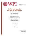
GenICam features (page 139). Alternatively, the Point Grey GigE Configurator is a tool included with
the camera software and drivers package that allows you to set the internet protocol (IP)
configuration for any GigE interface cards or Point Grey GigE Vision cameras connected to your
system. Using the GigE configurator, you can:
Revised 9/27/2011
Copyright © 2011 Point Grey Research, Inc.
18
Point Grey Grasshopper2 Technical Reference
l
l
l
2 General Camera Operation
Set the IP address for the current connection.
Program a persistent IP address for the camera.
Configure the default IP addressing behavior of the camera on startup using a persistent IP,
DHCP or LLA.
For more information, refer to the online Help file included with the tool.
To open the Point Grey GigE Configurator
Start > Point Grey Research > FlyCapture2 > Utilities > GigEConfigurator
Figure 2.1: Point Grey GigE Configurator
2.4
Configuring Other Network Settings
The following GigE Vision bootstrap registers can be used for configuring the camera on the
network. All registers are implemented according to the GigE Vision standard. A listing of all
network-related bootstrap registers supported on the camera is provided in GigE Vision Bootstrap
Registers on page 142.
2.4.1
Stream Channel Packet Size
The stream channel packet size (SCPS) sets the size, in bytes, of the packet to be sent out by the
camera. IP, UDP and GVSP headers are included in this size. The default SCPS is 1400 bytes. We
recommend increasing this value to maximize performance, since maximizing packet size reduces
processing overhead.
To accommodate the default SCPS of 1400 bytes, the frame rates when the camera
is powered on using the factory default settings are 20 FPS in Mode_8 (GS2-GE20S4) and 19 FPS (GS2-GE-50S5). Additionally, the GS2-GE-50S5 powers on with a
1920 x 1080 centered region of interest. To adjust the power-on default settings, see
User Configuration Sets on page 26. For information about frame rate and region of
interest, see Supported Formats, Modes and Frame Rates on page 45.
Revised 9/27/2011
Copyright © 2011 Point Grey Research, Inc.
19
Point Grey Grasshopper2 Technical Reference
2 General Camera Operation
When setting the SCPS, keep in mind the following:
l
l
Some network interface card switches and other network components cannot handle Jumbo
Frames, which are Ethernet frames with more than 1500 bytes of payload.
Changing the packet size may impact throughput depending on the packet delay setting. See
Stream Channel Packet Delay below.
SCPS can be controlled using the GevSCPSPacketSize GenICam feature or the GigE Vision
Booststrap registers (page 142). The FlyCapture SDK also supports configuring the SCPS. For
more information, consult the FlyCapture SDK Help.
For information about data packet format, see Packet Format on page 1.
2.4.2
Stream Channel Packet Delay
The stream channel packet delay (SCPD) register is used to manage camera bandwidth. It indicates
the number of ticks (at the frequency of the Timestamp Tick Frequency) to insert between each
packet. The default SCPD is 400. Increasing SCPD lowers the amount of bandwidth available to the
camera on the network.
The Point Grey Timestamp Tick Frequency is normally 25,000,000 ticks/second, but can be verified
by the Timestamp Tick Frequency register (page 142).
Raising the SCPD may require the frame rate to be reduced to meet the maximum
bandwidth restriction of the SCPD setting. Achieving a desired frame rate may
require lowering the SCPD .
SCPD can also be controlled using the GevSCPD GenICam feature (page 139) or the GigE Vision
bootstrap registers (page 142). The FlyCapture SDK also supports configuring the SCPD. For more
information, consult the FlyCapture SDK Help.
!
Lowering SCPD may cause the bottom rows of images to be black. To fix, try one or
more of the following:
l
l
l
2.4.3
Use the Point Grey Image Filter Driver with the camera. For more information,
see Configuring Camera Drivers on page 23.
Increase stream channel packet size (SCPS) as an alternative to securing
more bandwidth. For more information, see Stream Channel Packet Size on
previous page
Use a PCI Express (PCIe) network interface card for interfacing with the camera. For more information, see GigE Network Interface Card on page 38
Heartbeat
The heartbeat is a mandatory GigE Vision feature to monitor the connection between an application
and the camera. The application must reset the heartbeat timer, or the camera will assume an error
has occurred and shut down the connection. In general, the FlyCapture API manages the heartbeat
at a low level, however the following two features are controllable. Typically they are used when
debugging code and setting breakpoints. Unless the heartbeat is disabled, the connection will
timeout.
Revised 9/27/2011
Copyright © 2011 Point Grey Research, Inc.
20
Point Grey Grasshopper2 Technical Reference
2.4.3.1
2 General Camera Operation
Heartbeat Timeout
Heartbeat time is the time, in ms, that the camera will wait between resets from the
application.Heartbeat Timeout can be set between 500 ms and 10 s. The default setting is 3000 ms.
Heartbeat timeout can be controlled using the GevHeartbeatTimeout GenICam feature (page
139) or the GigE Vision bootstrap registers (page 142) . The FlyCapture SDK also supports
configuring heartbeat timeout. For more information, consult the FlyCapture SDK Help.
2.4.3.2
Heartbeat Disable
Heartbeat disable allows the heartbeat function in the camera to be disabled. The heartbeat is
enabled by default.
The heartbeat can be controlled using the GevGVCPHeartbeatDisable GenICam feature (page
139) or the GigE Vision bootstrap registers (page 142) . The FlyCapture SDK also supports
configuring the heartbeat. For more information, consult the FlyCapture SDK Help.
2.4.4
Determining Bandwidth Requirements
The following examples illustrate the relationship between packet size (page 19), packet delay (page
20) and data throughput on the GigE network, and how to ensure enough bandwidth is available for a
given image size and frame rate.
GenICam applications can obtain data throughput calculations using the DeviceMaximumThroughput, DeviceAssignedBandwidth and DeviceCurrentThroughput
Device Control features. For more information, see GenICam Features on page 139.
Example 1
This example illustrates that a packet size of 9000 bytes and a packet delay of 400 ticks (default
setting) results in just over 2/3 usage of GigE bandwidth (693 Mb/sec). This configuration provides
adequate bandwidth for a GS2-20S4 camera operating at 1600x1200 resolution in 8 bit/pixel format,
at the maximum achievable frame rate of 30 FPS (461 Mb/sec). The amount of GigE bandwidth used
in this example is limited only by the imaging requirements.
Packet Size: 9000 bytes
Packet Delay: 400 ticks
Link Speed: 1 Gbit/sec
Resolution: 1600 x 1200
FPS: 30
Pixel Format: Raw8
total packet time = time to transmit packet + packet delay
Time to transmit 9000 byte packet: 9000 * 8 bits per pixel = 72,000 bits
72,000 bits / 1,000,000,000 bps = 72 µs
Packet delay: 400 ticks / 25,000,000 ticks per sec = 16 µs
Total packet time = 72 µs + 16 µs = 88 µs
data throughput (bandwidth) = packet size / total packet time
Packet size / total packet time = (8972 bytes * 8 bits per pixel) / 88 µs = 815 Mbits per sec
Revised 9/27/2011
Copyright © 2011 Point Grey Research, Inc.
21
Point Grey Grasshopper2 Technical Reference
2 General Camera Operation
Bandwidth = 815 Mbit per sec * 0.85 = 693 Mbit per sec
Notes: 1) 9000-byte packet is reduced by 28 bytes to 8972 bytes due to header information
included with every Ethernet packet; 2) Available bandwidth is reduced by 15% for
communications control.
imaging bandwidth = resolution * bit depth * frame rate
Imaging bandwidth = 1600 * 1200 * 8 bits per pixel * 30 FPS = 461 Mbit per sec
Example 2
This example illustrates that a packet size of 1400 bytes (default setting) and a packet delay of 1000
ticks provides only 182 Mb/sec of GigE bandwidth usage. This configuration does not provide
adequate bandwidth for a GS2-50S5 operating at maximum resolution in 8 bit/pixel format, at the
maximum supported frame rate of 15 FPS (602 Mb/sec). In this case, throughput is limited by the
amount of network bandwidth available. Frame rate must be lowered to 4.5 FPS to operate within the
specified networking parameters.
Packet Size: 1400 bytes
Packet Delay: 1000 ticks
Link Speed: 1 Gbit/sec
Resolution: 2448 x 2048
FPS: 15
Pixel Format: Raw8
total packet time = time to transmit packet + packet delay
Time to transmit 1400 byte packet: 1400 * 8 bits per pixel = 11,200 bits
11,200 bits / 1,000,000,000 bps = 11.2 µs
Packet delay: 1000 ticks / 25,000,000 ticks per sec = 40 µs
Total packet time = 11.2 µs + 40 µs = 51.2 µs
data throughput (bandwidth) = packet size / total packet time
Packet size / total packet time = (1372 bytes * 8 bits per pixel) / 51.2 µs = 214 Mbits per sec
Bandwidth = 214 Mbit per sec * 0.85 = 182 Mbit per sec
Notes: 1) 1400-byte packet is reduced by 28 bytes to 1372 bytes due to header information
included with every Ethernet packet; 2) Available bandwidth is reduced by 15% for
communications control.
imaging bandwidth = resolution * bit depth * frame rate
Imaging bandwidth = 2448 * 2048 * 8 bits per pixel * 15 FPS = 602 Mbit per sec
achievable frame rate = available bandwidth / bit depth / resolution
Achievable frame rate=182 / 8 bits per pixel / (2448 * 2048) = 4.5 FPS
2.4.4.1
Bandwith Requirements for Multiple Cameras
The total throughput of multiple cameras that operate on a single GigE connection through a network
switch must fall within the available GigE bandwidth specification of 1 Gbps. Considering the
cameras in the previous examples, the camera in the first example uses 461 Mbps of bandwidth,
and the camera in the second example uses 182 Mbps (assuming its frame rate is reduced to 4.5
FPS). If these two cameras operated together, the total throughput would be 643 Mbps, which falls
within available GigE bandwidth. If, however, the second camera's network parameters were
changed to it allow it to operate at 15 FPS, its throughput of 602 Mbps, together with the first
Revised 9/27/2011
Copyright © 2011 Point Grey Research, Inc.
22
Point Grey Grasshopper2 Technical Reference
2 General Camera Operation
camera's throughput, would exceed the GigE bandwidth specification, resulting in unexpected
imaging behavior such as dropped packets and lost images.
2.5
Configuring Camera Drivers
Point Grey provides the Image Filter Driver for use with GigE Vision cameras. This driver operates
as a network service between the camera and the Microsoft built-in UDP stack to filter out GigE
vision stream protocol (GVSP) packets. The filter driver is installed and enabled by default as part of
the FlyCapture SDK installation process. Use of the filter driver is recommended, as it can reduce
CPU load and improve image streaming performance. Alternatively, Point Grey GigE Vision
cameras can operate without the filter driver by communicating directly with the Microsoft UDP
stack. GigE Vision cameras operating on Linux systems can communicate directly with native
Ubuntu drivers.
For more information about the image filter driver, see the FlyCapture SDK Help.
2.6
Managing Camera Settings
2.6.1
Using the Control and Status Registers
2.6.1.1
IIDC 1394-Compatible Registers
The user can monitor or control each feature of the camera through the control and status registers
(CSRs) programmed into the camera firmware. To facilitate migration from existing, FireWire-based
applications, these registers are compatible with v1.32 of the Instrumentation & Industrial Digital
Camera (IIDC) 1394 registers found in Point Grey FireWire cameras. Format tables for each 32-bit
register are presented along with their respective feature descriptions throughout this manual. These
tables describe the purpose of each bit that comprises the register. Bit 0 is always the most
significant bit of the register value.
Register offsets and values are generally referred to in their hexadecimal forms, represented by
either a ‘0x’ before the number or ‘h’ after the number, e.g. the decimal number 255 can be
represented as 0xFF or FFh.
For more information about camera registers, including the base register
memory map, config ROM offsets and calculating register addresses,
see General Register Information on page 116
The controllable fields of most registers are Mode and Value.
Mode:
Each CSR has three bits for mode control, ON_OFF, One_ Push and A_M_Mode (Auto/Manual
mode). Each feature can have four states corresponding to the combination of mode control bits.
Not all features implement all modes.
Revised 9/27/2011
Copyright © 2011 Point Grey Research, Inc.
23
Point Grey Grasshopper2 Technical Reference
One_Push
ON_OFF
A_M_Mode
2 General Camera Operation
State
N/A
0
N/A
Off state.
Feature will be fixed value state and uncontrollable.
N/A
1
1
Auto control state.
Camera controls feature by itself continuously.
0
1
0
Manual control state.
User can control feature by writing value to the value
field.
1
(Self clear)
1
0
One-Push action.
Camera controls feature by itself only once and returns
to the Manual control state with adjusted value.
Table 2.1: CSR Mode Control Descriptions
Value:
If the Presence_Inq bit of the register is one, the value field is valid and can be used for controlling
the feature. The user can write control values to the value field only in the Manual control state. In
the other states, the user can only read the value. The camera always has to show the real setting
value at the value field if Presence_Inq is one.
2.6.1.2
Using the Inquiry Registers
The camera provides a series of inquiry registers, which allow you to reference basic information
about camera features. For information about the following inquiry registers, see Inquiry Registers
on page 120:
l
l
l
Inquiry Registers for Basic Functions and Feature Presence: To determine if a particular function or feature is available on the camera.
Inquiry Registers for Feature Elements : To determine if elements of a particular feature are
available on the camera.
Video Format, Mode and Frame Rate Inquiry Registers: To determine which standard video
format, modes and frame rates are available on the camera.
The following additional inquiry registers are also available:
l
l
2.6.1.3
Inquiry Registers for Format_7 Video Modes (page 129)
Inquiry Registers for Lookup Table Functionality (page 92)
Using the Absolute Value Registers
Many Point Grey IEEE-1394 cameras implement “absolute” modes for various camera settings that
report real-world values, such as shutter time in seconds (s) and gain value in decibels (dB). Using
these absolute values is easier and more efficient than applying complex conversion formulas to the
information in the Value field of the associated Control and Status Register. A relative value does
not always translate to the same absolute value. Two properties that can affect this relationship are
pixel clock frequency and horizontal line frequency. These properties are, in turn, affected by such
properties as resolution, frame rate, region of intererest (ROI) size and position, and packet size.
Additionally, conversion formulas can change between firmware versions. Point Grey therefore
recommends using absolute value registers, where possible, to determine camera values.
For more information, see Absolute Value Registers on page 134.
Revised 9/27/2011
Copyright © 2011 Point Grey Research, Inc.
24
Point Grey Grasshopper2 Technical Reference
2.6.1.4
2 General Camera Operation
GigE Vision Bootstrap Registers
The camera is programmed with a number of GigE Vision-compliant bootstrap registers for storing
camera metadata and controlling network management settings. For a listing of all GigE Vision
bootstrap registers on the camera, see GigE Vision Bootstrap Registers on page 142.
2.6.2
Operating System and Software Support
2.6.2.1
FlyCap Demo Program
The FlyCap application is a generic, easy- to- use streaming image viewer included with the
FlyCapture® SDK that can be used to test many of the capabilities of your compatible Point Grey
camera. It allows you to view a live video stream from the camera, save individual images, adjust
the various video formats, frame rates, properties and settings of the camera, and access camera
registers directly. Consult the FlyCapture SDK Help for more information.
2.6.2.2
Custom Applications Built with the FlyCapture API
The FlyCapture SDK includes a full Application Programming Interface that allows customers to
create custom applications to control Point Grey Imaging Products. Included with the SDK are a
number of source code examples to help programmers get started.
2.6.2.3
GenICam Applications
The camera includes an XML device description file for interfacing with third- party GenICamcompliant APIs. This file can be accessed via First URL bootstrap register 200h (page 142). A listing
of features that are included in the XML file is provided in GenICam Features on page 139.
2.6.2.4
Recommended Hardware and Software Requirements
Hardware Requirements
l
l
l
l
l
Intel Core 2 dual or comparable PC
2 GB RAM
GigE Network Interface Card (page 38)
Ethernet Cable (page 38)
Power Supply (page 18)
Software Requirements (Windows)
l
l
l
l
Windows XP (Service Pack 3), Windows Vista (Service Pack 1) or Windows 7
MS Visual Studio 6.0 SP5 (to compile and run example FlyCapture SDK code on Windows
XP 32-bit)
MS Visual Studio 2005 SP1 (to compile and run example FlyCapture SDK code on Windows
XP 64-bit)
MS Visual Studio 2005 SP1 and SP1 Update for Vista (to compile and run example code on
Windows Vista or Windows 7)
Software Requirements (Linux)
l
l
Ubuntu 8.04
gtkmm-2.4-dev and libgtkmm-2.4-dev dependencies to compile and run graphical user interface-based example code. (These libraries are usually pre-installed.)
Revised 9/27/2011
Copyright © 2011 Point Grey Research, Inc.
25
Point Grey Grasshopper2 Technical Reference
2 General Camera Operation
For more information about operating system compatibility, see Knowledge Base Article 258. For
more information about recommended requirements for working with the FlyCapture SDK, see the
FlyCapture SDK Help.
2.6.2.5
Macintosh and Linux OS Support
Users wishing to operate their Point Grey camera on the Macintosh OS/X or Linux operating
systems should consult the following knowledge base articles:
Macintosh support:
www.ptgrey.com/support/kb/index.asp?a=4&q=173
Linux support:
www.ptgrey.com/support/kb/index.asp?a=4&q=330
www.ptgrey.com/support/kb/index.asp?a=4&q=17
2.6.3
User Configuration Sets
The camera can save and restore settings and imaging parameters via on-board configuration sets,
also known as memory channels. This is useful for saving default power-up settings, such as gain,
shutter, video format and frame rate, and others that are different from the factory defaults.
Memory channel 0 is used for the default factory settings that users can always restore to. Two
additional memory channels are provided for custom default settings. The camera will initialize itself
at power-up, or when explicitly reinitialized, using the contents of the last saved memory channel.
Attempting to save user settings to the (read-only) factory defaults channel will cause the camera to
switch back to using the factory defaults during initialization.
For a listing of all registers saved, see Memory Channel Registers on next page.
MEMORY_SAVE: 618h
Format:
Field
Bit
Description
Memory_Save
[0]
1 = Current status and modes are saved to MEM_SAVE_CH
(Self cleared)
[1-31]
Reserved.
MEM_SAVE_CH: 620h
Format:
Field
Bit
Description
Mem_Save_Ch
[0-3]
Write channel for Memory_Save command.
Shall be >=0001 (0 is for factory default settings)
See BASIC_FUNC_INQ register.
[4-31]
Reserved.
Revised 9/27/2011
Copyright © 2011 Point Grey Research, Inc.
26
Point Grey Grasshopper2 Technical Reference
2 General Camera Operation
CUR_MEM_CH: 624h
Format:
2.6.3.1
Field
Bit
Description
Cur_Mem_Ch
[0-3]
Write: Loads the camera status, modes and values from the
specified memory channel.
Read: The current memory channel number.
[4-31]
Reserved.
Memory Channel Registers
The values of the following registers are saved in memory channels.
Register Name
Offset
CURRENT_FRAME_RATE
600h
CURRENT_VIDEO_MODE
604h
CURRENT_VIDEO_FORMAT
608h
CAMERA_POWER
610h
CUR_SAVE_CH
620h
BRIGHTNESS
800h
AUTO_EXPOSURE
804h
SHARPNESS
808h
WHITE_BALANCE
80Ch
HUE
810h
SATURATION
814h
GAMMA
818h
SHUTTER
81Ch
GAIN
820h
IRIS
824h
FOCUS
828h
TRIGGER_MODE
830h
TRIGGER_DELAY
834h
FRAME_RATE
83Ch
PAN
884h
TILT
888h
Revised 9/27/2011
Copyright © 2011 Point Grey Research, Inc.
27
Point Grey Grasshopper2 Technical Reference
Register Name
2 General Camera Operation
Offset
ABS_VAL_AUTO_EXPOSURE
908h
ABS_VAL_SHUTTER
918h
ABS_VAL_GAIN
928h
ABS_VAL_BRIGHTNESS
938h
ABS_VAL_GAMMA
948h
ABS_VAL_TRIGGER_DELAY
958h
ABS_VAL_FRAME_RATE
968h
IMAGE_DATA_FORMAT
1048h
AUTO_EXPOSURE_RANGE
1088h
AUTO_SHUTTER_RANGE
1098h
AUTO_GAIN_RANGE
10A0h
GPIO_XTRA
1104h
SHUTTER_DELAY
1108h
GPIO_STRPAT_CTRL
110Ch
GPIO_CTRL_PIN_x
1110h, 1120h, 1130h,
1140h
GPIO_XTRA_PIN_x
1114h, 1124h, 1134h,
1144h
GPIO_STRPAT_MASK_PIN_x
1118h, 1128h, 1138h,
1148h
FRAME_INFO
12F8h
IMAGE_POSITION
008h
IMAGE_SIZE
00Ch
COLOR_CODING_ID
010h
GVCP Configuration (includes Heartbeat Disable) (GigE Vision Bootstrap Register)
0954h (no offset)
Stream Channel Packet Size (GigE Vision Bootstrap Register)
0D04h (no offset)
Stream Channel Packet Delay (GigE Vision Bootstrap Register)
0D08h (no offset)
Heartbeat Timeout (GigE Vision Bootstrap Register)
0938h (no offset)
Revised 9/27/2011
Copyright © 2011 Point Grey Research, Inc.
28
Point Grey Grasshopper2 Technical Reference
2 General Camera Operation
2.7
Camera Error and Status Monitoring
2.7.1
Main Status Indicator LED
2.7.1.1
LED Behavior During Camera Power-up and Initialization
Status
LED Behavior
Approximate
Time
1. Camera powers up and programs
the FPGA
Steady green, high intensity
5 seconds
2. Camera boots up
Steady green, low intensity
2 seconds
One, two or three green blinks. See
following table
1-2 seconds
3. Establishing IP connection
4. Camera is streaming images
Steady green, high intensity
Table 2.2: LED Behavior During Power-up and Initialization
The camera attempts to establish an IP connection in the following order: 1) A persistent IP address,
if enabled and available; 2) a DHCP address, if enabled and available; 3) a link-local address (LLA).
The LED behavior at this stage of initialization (step 3 in the table above) is as follows:
IP Connection Blink Behavior
(3 blinks total)
Type of Connection Established
One green blink
Persistent IP
Two green blinks
DHCP
Three green blinks
LLA
LED remains steady green, low intensity
Failure to establish connection
Table 2.3: LED Behavior During IP Connection
For more information about IP addressing, see Configuring the IP Address on page 18.
2.7.1.2
LED Behavior During Regular Camera Operation
LED Status
Description
Off
Not receiving power
Steady green, high intensity
Streaming images
Three (3) red flashes
Ethernet connection failure
Red flashing slowly
General error - contact technical support (page 114)
Table 2.4: LED Behavior During Regular Camera Operation
Revised 9/27/2011
Copyright © 2011 Point Grey Research, Inc.
29
Point Grey Grasshopper2 Technical Reference
2.7.2
2 General Camera Operation
GigE Connector Indicator LEDs
The RJ-45 Ethernet jack includes two status LEDs: a green LED to the left of the jack, and an
orange LED to the right. These LEDs indicate connection status and activity on the Ethernet
network.
2.7.2.1
LED Behavior During Camera Power-up and Initialization
On camera power- up, both LEDs turn on for approximately one second once the camera is
initialized, then turn off until an IP connection is established and image streaming begins.
2.7.2.2
LED Behavior during Regular Camera Operation
Green LED (left)
Description
Off
No Ethernet link established between camera and host controller.
On
Ethernet link established.
Orange LED (right)
Description
Off
No image streaming activity on the Ethernet connection
Blinking
Indicates sporadic activity on the connection
Solid On
Indicates continuous activity on the connection, such as video
streaming or flash data writing
Table 2.5: GigE Connector LED Behavior
LED_CTRL: 1A14h
This register allows the user to turn off the camera’s status LED. LED(s) are re-enabled the next
time the camera is power cycled.
On GigE Vision cameras, this register enables or disables both the main camera
status LED and the GigE connector indicator LEDs, if equipped.
Format:
Field
Bit
Description
Presence_Inq
[0]
Presence of this feature
0: N/A 1: Available
[1-22]
Reserved
[23-31]
Enable or disable the LED
0x00: Off, 0x74: On
LED_Ctrl
Revised 9/27/2011
Copyright © 2011 Point Grey Research, Inc.
30
Point Grey Grasshopper2 Technical Reference
2.7.3
2 General Camera Operation
General Status Monitoring
INITIALIZE: 000h
Format:
Offset
Name
Field
Bit
Description
000h
INITIALIZE
Initialize
[0]
If this bit is set to 1, the camera will reset
to its initial state and default settings. This
bit is self-cleared.
-
[1-31]
Reserved
TIME_FROM_INITIALIZE: 12E0h
This register reports the time, in seconds, since the camera (FPGA) was initialized. This
initialization occurs during a hard power-up. This is different from powering up the camera via the
CAMERA_POWER (page 18) register, which will not reset this time.
Format:
Field
Bit
Description
Presence_Inq
[0]
Presence of this feature
0: N/A 1: Available
Time_From_Init
[1-31]
Time in seconds since the camera was initialized.
LINK_UP_TIME: 12E4h
This register reports the time, in seconds, since the last Ethernet re-connection occurred. This will
be equal to the value reported by TIME_FROM_INITIALIZE (page 31) if no reset has occurred since
the last time the camera was initialized.
Format:
Field
Bit
Description
Presence_Inq
[0]
Presence of this feature
0: N/A 1: Available
Time_From_Reset
[1-31]
Time in seconds since the camera detected a re-connection.
VOLTAGE: 1A50h – 1A54h
This register allows the user to access and monitor the various voltage registers supported by the
camera.
Revised 9/27/2011
Copyright © 2011 Point Grey Research, Inc.
31
Point Grey Grasshopper2 Technical Reference
2 General Camera Operation
Format:
Offset
Name
Field
Bit
1A50h
VOLTAGE_LO_
INQ
Presence_Inq [0]
Presence of this feature
0: Not available, 1: Available
-
[1-7]
Reserved
[8-19]
Number of voltage registers supported
[20-31]
Reserved
[0-31]
Quadlet offset of the voltage CSR’s,
which report the current voltage in Volts
using the 32- bit floating- point
IEEE/REAL*4 format.
1A54h
VOLTAGE_HI_INQ
Description
CURRENT: 1A58h-1A5Ch
This register allows the user to access and monitor the various current registers supported by the
camera.
Format:
Offset
Name
Field
Bit
1A58h
CURRENT_ Presence_ [0]
LO_INQ
Inq
Description
Presence of this feature
0: Not available, 1: Available
[1-7]
Reserved
[8-19]
Number of current registers supported
[20-31] Reserved
1A5Ch CURRENT_
HI_INQ
[0-31]
Quadlet offset of the current CSR’s, which
report the current in amps using the 32-bit
floating-point IEEE/REAL*4 format.
TEMPERATURE: 82Ch
Allows the user to get the temperature of the camera board-level components. For cameras housed
in a case, it is the ambient temperature within the case. Value is in kelvins (0°C = 273.15K) in
increments of one-tenth (0.1) of a kelvin.
For more information about camera temperature, see Case Temperature and Heat Dissipation on
page 17.
Format:
Field
Bit
Description
Presence_Inq
[0]
Presence of this feature
0: N/A, 1: Available
Abs_Control
[1]
Absolute value control
0: Control with the value in the Value field
1: Control with the value in the Absolute value CSR.
If this bit = 1, the value in the Value field is read-only.
[2-4]
Reserved
Revised 9/27/2011
Copyright © 2011 Point Grey Research, Inc.
32
Point Grey Grasshopper2 Technical Reference
Field
Bit
Description
One_Push
[5]
One push auto mode (controlled automatically by camera only
once)
Write: 1: Begin to work (self-cleared after operation)
Read: 0: Not in operation, 1: In operation
If A_M_Mode = 1, this bit is ignored
ON_OFF
[6]
Write: ON or OFF for this feature
Read: read a status
0: OFF, 1: ON
If this bit = 0, other fields will be read only
A_M_Mode
[7]
Read: read a current mode
0: Manual, 1: Automatic
[8-19]
Reserved
[20-31]
Value.
A write to this value in ‘Auto’ mode will be ignored.
Value
2.7.4
2 General Camera Operation
Error Status Registers
XMIT_FAILURE: 12FCh
This register contains a count of the number of failed frame transmissions that have occurred since
the last reset.
Format:
Field
Bit
Description
Presence_Inq
[0]
Presence of this feature
0: N/A 1: Available
Frame_Count
[1-31]
Read: Count of failed frame transmissions.
Write: Reset.
VMODE_ERROR_STATUS: 628h
This register is used by the camera to report any camera configuration errors. If an error has
occurred, no image data will be sent by the camera.
Format:
Field
Bit
Description
Vmode_Error_Status
[0]
Error status of combination of video format, mode, frame rate
and ISO_SPEED setting.
0: no error
1: error
This flag will be updated every time one of the above settings is
changed by writing a new value.
[1-31]
Reserved.
Revised 9/27/2011
Copyright © 2011 Point Grey Research, Inc.
33
Point Grey Grasshopper2 Technical Reference
2.7.5
2 General Camera Operation
Device Information
PIXEL_CLOCK_FREQ: 1AF0h
This register specifies the current pixel clock frequency (in Hz) in IEEE-754 32-bit floating point
format. The camera pixel clock defines an upper limit to the rate at which pixels can be read off the
image sensor.
Format:
Field
Bit
Description
Pixel_Clock_Freq
[0-31]
Pixel clock frequency in Hz (read-only).
HORIZONTAL_LINE_FREQ: 1AF4h
This register specifies the current horizontal line frequency in Hz in IEEE-754 32-bit floating point
format.
Format:
Field
Bit
Description
Horizontal_Line_Freq
[0-31]
Horizontal line frequency in Hz (read-only).
SERIAL_NUMBER: 1F20h
This register specifies the unique serial number of the camera.
Format:
Field
Bit
Description
Serial_Number
[0-31]
Unique serial number of camera (read-only)
MAIN_BOARD_INFO: 1F24h
This register specifies the type of camera (according to the main printed circuit board).
Format:
Field
Bit
Major_Board_Design
[0-11]
Minor_Board_Rev
[12-15]
Internal use
Reserved
[16-31]
Reserved
Revised 9/27/2011
Copyright © 2011 Point Grey Research, Inc.
Description
0x2: Digiclops
0x3: Dragonfly
0x4: Sync Unit
0x6: Ladybug Head
0x7: Ladybug Base Unit
0x8: Bumblebee
0xA: Scorpion Back Board
0x10: Flea
0x12: Dragonfly Express
0x18: Dragonfly2
0x19: Flea2
0x1A: Firefly MV
0x1C: Bumblebee2
0x1F: Grasshopper
0x22: Grasshopper2
0x21: Flea2G-13S2
0x24: Flea2G-50S5
0x26: Chameleon
0x2B: Flea3
0x36: Zebra2
34
Point Grey Grasshopper2 Technical Reference
2 General Camera Operation
SENSOR_BOARD_INFO: 1F28h
This register specifies the type of imaging sensor used by the camera (due to the wide variety of
sensors available).
The interpretation of this register varies depending on the camera
type, as defined in the MAIN_BOARD_INFO register 0x1F24 (page
34) Read MAIN_BOARD_INFO to determine how to use the Sensor_
Type_x fields.
Format:
Field
Bit
Description
Sensor_Type_1
[0-11]
tbd
Minor_Board_Rev
[12-15]
Internal use
Reserved
Sensor_Type_2
[16-27]
[28-31]
Reserved
tbd
BUILD_TIMESTAMP: 1F40h
This register specifies the date that the current version of the firmware was built in Unix time format.
Format:
Field
Bit
Description
Build_Date
[0-31]
Date firmware was built (read-only)
FIRMWARE_VERSION: 1F60h
This register contains the version information for the currently loaded camera firmware. For more
information on Point Grey versioning standards, see Knowledge Base Article 96
(http://www.ptgrey.com/support/kb/index.asp?a=4&q=96).
Format:
Field
Bit
Description
Major
[0-7]
Major revision number
Minor
[8-15]
Minor revision number
Type
[16-19]
Type of release
0: Alpha
1: Beta
2: Release Candidate
3: Release
Revision
[20-31]
Revision number
FIRMWARE_BUILD_DATE: 1F64h
Specifies the date that the current version of the firmware was built in Unix time format.
Revised 9/27/2011
Copyright © 2011 Point Grey Research, Inc.
35
Point Grey Grasshopper2 Technical Reference
2 General Camera Operation
Format:
Field
Bit
Description
Build_Date
[0-31]
Date firmware was built (read-only)
FIRMWARE_DESCRIPTION: 1F68-1F7Ch
Null padded, big-endian string describing the currently loaded version of firmware.
2.8
Non-Volatile Flash Memory
The camera has 512 KB of non-volatile memory for users to store data.
DATA_FLASH_CTRL: 1240h
This register controls access to the camera’s on-board flash memory. Each bit in the data flash is
initially set to 1.
Format:
Field
Bit
Description
Presence_Inq
[0]
Presence of this feature
0: N/A 1: Available
[1-5]
Reserved
[6]
Write:
1: Write page to data flash
0: No-op
Read:
1: Page is clean
0: Page is dirty
[7]
Reserved
Page_Size
[8-19]
8 == 256 byte page
9 == 512 byte page
Num_Pages
[20-31]
11 == 2048 pages
13 == 8192 pages
Clean_Page
DATA_FLASH_DATA: 1244h
This register provides the quadlet offset to the start of the actual data contained in the flash memory
(query DATA_FLASH_CTRL register 1240h (page 36) ).
Any access outside of a modified page will automatically cause the page to be rewritten to flash, i.e.
the user can write as much information as necessary, then perform a single write to the DATA_
FLASH_CTRL register 1240h.
Format:
Field
Bit
Description
DF_Data
[0-31]
Quadlet offset to the start of data
Revised 9/27/2011
Copyright © 2011 Point Grey Research, Inc.
36
Point Grey Grasshopper2 Technical Reference
2.9
2 General Camera Operation
Upgrading Camera Firmware
Camera firmware can be upgraded or downgraded to later or earlier versions using the UpdatorGUI2
program that is bundled with every firmware version available from
www.ptgrey.com/support/downloads . The latest firmware versions often include significant bug
fixes and feature enhancements. To determine the changes made in a specific firmware version,
consult the Release Notes. For more information on updating camera firmware, consult the
UpdatorGUI2 User Manual, included with the firmware bundle.
Revised 9/27/2011
Copyright © 2011 Point Grey Research, Inc.
37
Point Grey Grasshopper2 Technical Reference
3 Camera Interface and Connectors
3
Camera Interface and Connectors
3.1
GigE Connector
The 8-pin RJ-45 Ethernet jack is equipped with two (2) M2 screwholes for secure connection. Pin
assignments conform to the Ethernet standard. For information about the orange and green status
LEDs on each side of the connector, see GigE Connector Indicator LEDs on page 30.
3.2
Cables
Category 5e or 6 cables up to 100 meters in length should be used for connecting the camera to the
GigE network interface card on the host system. Point Grey sells a 5-meter Category 5e cable for
this purpose. For more information, visit the cable accessories page on the Point Grey website, at
http://www.ptgrey.com/products/accessories/index.asp?type=cables. (Part No. ACC-01-2100)
3.3
GigE Network Interface Card
A 1000 Mbps GigE network interface card (NIC) is required for streaming images on the Ethernet
network between the camera and host system. Point Grey sells a GigE PCI Express (PCIe) card for
this purpose. For more information, visit the interface card accessories page on the Point Grey
website, at http://www.ptgrey.com/products/accessories/index.asp?type=cards . (Part No. ACC01-1100)
For optimal video streaming and camera control performance, we recommend a PCIe
interface equipped with an Intel PRO 1000 chipset.
3.4
General Purpose Input/Output (GPIO)
The camera has an 8-pin GPIO connector on the back of the case. The connector is a Hirose HR25
8 pin connector (Mfg P/N: HR25-7TR-8SA).
Revised 9/27/2011
Copyright © 2011 Point Grey Research, Inc.
38
Point Grey Grasshopper2 Technical Reference
Diagram
3 Camera Interface and Connectors
Pin
Function
Function
1
IO0
Opto-isolated input (default Trigger in)
2
IO1
Opto-isolated output
3
IO2
Input / Output / serial transmit (TX)
4
IO3
Input / Output / serial receive (RX)
5
GND
6
GND
Ground for opto-isolated IO pins
7
VEXT
Allows the camera to be powered externally
8
+3.3 V
Power external circuitry up to 150 mA
Ground for bi-directional IO, V
EXT
, +3.3 V pins
Table 3.1: GPIO pin assignments (as shown looking at rear of camera)
Inputs can be configured to accept external trigger signals. Outputs can be configured to send an
output signal. For information about I/O configuration, refer to the following sections:
l
l
l
3.4.1
Asynchronous External Trigger Modes (page 53)
Programmable Strobe Output (page 66)
Pulse Width Modulation (PWM) (page 73)
GPIO Electrical Characteristics
The GPIO pins are TTL 3.3V pins. When configured as inputs, the pins are internally pulled high
using weak pull-up resistors to allow easy triggering of the camera by simply shorting the pin to
ground (GND). Inputs can also be directly driven from a 3.3V or 5V logic output. The inputs are
protected from both over and under voltage. It is recommended, however, that they only be
connected to 5V or 3.3V digital logic signals. When configured as outputs, each line can sink 10mA
of current. To drive external devices that require more, consult the following article for information on
buffering an output signal using an optocoupler:
KB Article 200: www.ptgrey.com/support/kb/index.asp?a=4&q=200
The VEXT pin (Pin 7) allows the camera to be powered externally. The voltage limit is 12-24 V, and
current is limited to 1A.
The +3.3V pin is fused at 150mA. External devices connected to Pin 8 should not attempt to pull
anything greater than that.
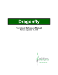
3.4.2
GPIO0 (Opto-Isolated Input) Circuit
The figure below shows the schematic for the opto-isolated input circuit.
Revised 9/27/2011
Copyright © 2011 Point Grey Research, Inc.
39
Point Grey Grasshopper2 Technical Reference
3 Camera Interface and Connectors
Figure 3.1: Optical input circuit
l
l
l
l
l
3.4.3
Logical 0 input voltage: 0 VDC to +1 VDC (voltage at OPTO_IN)
Logical 1 input voltage: +1.5 VDC to +30 VDC (voltage at OPTO_IN)
Maximum input current: 8.3 mA
Behavior between 1 VDC and 1.5 VDC is undefined and input voltages between those
values should be avoided
Input delay time: 4 μs
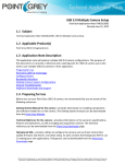
GPIO1 (Opto-Isolated Output) Circuit
The figure below shows the schematic for the opto-isolated output circuit. The maximum current
allowed through the opto-isolated output circuit is 25 mA.
Figure 3.2: Optical output circuit
The following table lists the switching times for the opto-isolator in the output pin, assuming an
output VCC of 5 V and a 1 kΩ resistor.
Parameter
Value
Delay Time
9 μs
Rise Time
16.8 μs
Storage Time 0.52 μs
Fall Time
Revised 9/27/2011
Copyright © 2011 Point Grey Research, Inc.
2.92 μs
40
Point Grey Grasshopper2 Technical Reference
3 Camera Interface and Connectors
The following table lists several external voltage and resistor combinations that have been tested to
work with the opto-isolated output.
3.4.4
External Voltage
External Resistor
OPTO_OUT Voltage
OPTO_OUT Current
3.3 V
1 kΩ
0.56 V
2.7 mA
5V
1 kΩ
0.84 V
4.2 mA
12 V
2.4 kΩ
0.91 V
4.6 mA
24 V
4.7 kΩ
1.07 V
5.1 mA
30 V
4.7 kΩ
1.51 V
13.3 mA
GPIO 2 / 3 (Bi-Directional) Circuit
Figure 3.3: Figure 4: GPIO2 / 3 Circuit
3.4.4.1
Input Side
l
l
l
Logical 0 input voltage: 0 VDC to +0.5 VDC (voltage at GPIO2 / 3)
Logical 1 input voltage: +1.5 VDC to +30 VDC (voltage at GPIO2 / 3)
Behavior between 0.5 VDC and 1.5 VDC is undefined and input voltages between those
values should be avoided
To avoid damage, connect the ground (GND) pin first before
applying voltage to the GPIO line.
3.4.4.2
Output Side
The maximum output current allowed through the bi-directional circuit is 25mA (limit by PTC
resistor), and the output impedance is 40Ω.
Revised 9/27/2011
Copyright © 2011 Point Grey Research, Inc.
41
Point Grey Grasshopper2 Technical Reference
3 Camera Interface and Connectors
The following table lists several external voltage and resistor combinations that have been tested to
work with the bi-directional GPIO when configured as output.
External Voltage
External Resistor
GPIO2/3 Voltage
(Rexternal)
3.3 V
1 kΩ
0.157 V
5V
1 kΩ
0.218 V
12 V
1 kΩ
0.46 V
24 V
1 kΩ
0.86 V
30 V
1 kΩ
0.966 V
The following table lists the switching times for a standard GPIO pin, assuming an output VCC of 5V
and a 1kΩ resistor.
Parameter
Value
Delay Time
0.28 μs
Rise Time
0.06 μs
Storage Time 0.03 μs
Fall Time
Revised 9/27/2011
Copyright © 2011 Point Grey Research, Inc.
0.016 μs
42
Point Grey Grasshopper2 Technical Reference
4 Video Formats, Modes and Frame Rates
4
Video Formats, Modes and Frame Rates
4.1
Binning and ROI Modes
The camera implements a number of video modes that allow the user to select a specific region of
interest (ROI) of the image. Some modes also aggregate pixel values using either pixel binning or
subsampling. Specifying an ROI may increase frame rate. Modes that perform binning or
subsampling may increase image intensity.
"Binning" refers to aggregation that takes place in an analog manner, directly on the sensor before
read-out. "Subsampling" refers to aggregation that takes place digitally on the FPGA, after read-out.
Unless specified otherwise, color data is maintained in pixel binning/subsampling modes.
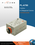
The figures below illustrate how binning/subsampling works. 2x vertical binning aggregates two
adjacent vertical pixel values to form a single pixel value. 2x horizontal binning works in the same
manner, except two adjacent horizontal pixel values are aggregated.
Figure 4.1: 2x Vertical and 2x Horizontal Binning
Some binning operations average the pixel values after aggregation. This type of binning is referred
to as "binning plus averaging, " and usually results in little or no change in overall image intensity.
Other binning operations do not perform any averaging after aggregation, which usually results in
increased intensity. Binning without averaging is referred to as "additive binning."
Changing the size of the image or the pixel encoding format requires the camera to be stopped and
restarted. Ignoring the time required to do this in software (tearing down, then reallocating, image
buffers, write times to the camera, etc.), the maximum amount of time required for the stop/start
procedure is slightly more than one frame time.
Additional binning information can be obtained by reading the FORMAT_7_RESIZE_INQ (page 130)
register 0x1AC8.
For information about configuring video mode, see Video Mode Control and Status Registers on
page 129.
Revised 9/27/2011
Copyright © 2011 Point Grey Research, Inc.
43
Point Grey Grasshopper2 Technical Reference
4.1.1
4 Video Formats, Modes and Frame Rates
Video Mode Descriptions
Mode_0
Mode_0 allows only for specifying a region of interest, and does not perform any binning. This mode
uses a faster pixel clock compared to Mode_7, which can result in faster frame rates when ROI
height is reduced.
Mode_1
Mode_1 implements 2X vertical and 2X horizontal additive binning. On color models, both horizontal
and vertical binning are performed as subsampling on the FPGA chip of the camera. On
monochrome models, vertical binning is performed on the sensor, and horizontal binning is
performed on the FPGA chip. This mode results in a resolution that is both half the width and half the
height of the original image. Mode_1 may result in an increase in brightness and improved signal-tonoise ratio, however no frame rate increase is achieved.
Mode_4
Mode_4 implements 2X vertical binning and 2X horizontal subsampling, and is available on color
models only. Horizontal subsampling is performed prior to color processing. Although image quality
may be poorer than in Mode_1, a frame rate increase is possible in this mode.
Mode_5
Mode_5 implements 4X vertical and 4X horizontal additive binning, resulting in a resolution that is
both one quarter the width and one quarter the height of the original image. On color models, Both
horizontal and vertical binning are performed as subsampling, on the FPGA chip of the camera. On
monochrome models, vertical binning is performed on the sensor, and horizontal binning is
performed on the FPGA chip. Mode_5 may result in an increase in brightness and improved signalto-noise ratio. However, no frame rate increase is achieved. This mode is not available in Raw pixel
formats.
Mode_6
Mode_6 is available on color models only, but only in monochrome pixel formats. This mode
implements 4X vertical binning and 4X horizontal subsampling, resulting in a resolution that is both
one quarter the width and one quarter the height of the original image.
Mode_7
Mode_7 allows only for specifying a region of interest, and does not perform any binning. This mode
uses a slower pixel clock, and is recommended for longer extended shutter times and/or improved
imaging performance. There may be no frame rate increase when ROI size is reduced.
Mode_8
Mode_8 is available on GS2-GE-20S4 models only. This mode is identical to Mode_0, except the
maximum resolution is 1600x1200, which runs at 30 FPS.
Revised 9/27/2011
Copyright © 2011 Point Grey Research, Inc.
44
Point Grey Grasshopper2 Technical Reference
4.2
4 Video Formats, Modes and Frame Rates
Calculating Maximum Possible Frame Rate
The maximum achievable frame rate for each camera on the network depends on available
bandwidth, pixel format (bit depth) and resolution, and can be determined using the following
formula:
Achievable_frame_rate = Available_bandwidth / Bit_depth / Resolution
Available bandwidth, in turn, depends on packet size (page 19) and packet delay (page 20). For
information about calculating available bandwidth, see Determining Bandwidth Requirements on
page 21.
For example, to calculate the maximum achievable frame rate of a camera operating at 2448x2048
resolution, 8 bit/pixel format, packet size 1400 bytes and packet delay 1000 ticks:
Achievable_frame_rate = 182 Mb/s (page 21) / 8 bit/pixel / (2448x2048)
Achievable_frame_rate = 4.5 FPS
4.3
Supported Formats, Modes and Frame Rates
The tables on the following pages show the supported pixel formats and mode combinations, along
with achievable frame rates at varying resolutions, for each camera model.
Revised 9/27/2011
Copyright © 2011 Point Grey Research, Inc.
45
Point Grey Grasshopper2 Technical Reference
4.3.1
4 Video Formats, Modes and Frame Rates
GS2-GE-20S4 Video Modes and Frame Rates
Max Frame Rate
Mode
Pixel Format
Max Size
(HxV)
Unit
Size
(H,V)
max
res
1280x
960
640x
480
320x
240
160x
120
0
Mono8
1624x1224
8,2
29
35
60
92
126
0
Mono12
1624x1224
8,2
29
35
60
92
126
0
Mono16
1624x1224
8,2
22
35
60
92
126
0
Raw8
1624x1224
8,2
29
35
60
92
126
0
Raw12
1624x1224
8,2
29
35
60
92
126
0
Raw16
1624x1224
8,2
22
35
60
92
126
0
RGB8
1624x1224
8,2
14
23
60
92
126
0
YUV411
1624x1224
8,2
29
35
60
92
126
0
YUV422
1624x1224
8,2
22
35
60
92
126
0
YUV444
1624x1224
8,2
14
23
60
92
126
1
Mono8
812x612
4,2
29
-
35
60
92
1
Mono12
812x612
4,2
29
-
35
60
92
1
Mono16
812x612
4,2
29
-
35
60
92
1
Raw8
812x612
4,2
29
-
35
60
92
1
Raw12
812x612
4,2
29
-
35
60
92
1
Raw16
812x612
4,2
29
-
35
60
92
1
RGB8
812x612
4,2
29
-
35
60
92
1
YUV411
812x612
4,2
29
-
35
60
92
1
YUV422
812x612
4,2
29
-
35
60
92
1
YUV444
812x612
4,2
29
-
35
60
92
4
Mono8
812x612
4,2
52
-
60
92
122
4
Mono12
812x612
4,2
52
-
60
92
122
4
Mono16
812x612
4,2
52
-
60
92
122
4
Raw8
812x612
4,2
52
-
60
92
122
4
Raw12
812x612
4,2
52
-
60
92
122
4
Raw16
812x612
4,2
52
-
60
92
122
4
RGB8
812x612
4,2
52
-
60
92
122
4
YUV411
812x612
4,2
52
-
60
92
122
4
YUV422
812x612
4,2
52
-
60
92
122
4
YUV444
812x612
4,2
52
-
60
92
122
5
Mono8
406x306
2,2
29
-
-
35
60
Revised 9/27/2011
Copyright © 2011 Point Grey Research, Inc.
46
Point Grey Grasshopper2 Technical Reference
4 Video Formats, Modes and Frame Rates
Max Frame Rate
Mode
Pixel Format
Max Size
(HxV)
Unit
Size
(H,V)
max
res
1280x
960
640x
480
320x
240
160x
120
5
Mono12
406x306
2,2
29
-
-
35
60
5
Mono16
406x306
2,2
29
-
-
35
60
5
RGB8
406x306
2,2
29
-
-
35
60
5
YUV411
406x306
2,2
29
-
-
35
60
5
YUV422
406x306
2,2
29
-
-
35
60
5
YUV444
406x306
2,2
29
-
-
35
60
6
Mono8
406x306
2,2
86
-
-
94
118
6
Mono12
406x306
2,2
86
-
-
94
118
6
Mono16
406x306
2,2
86
-
-
94
118
7
Mono8
1624x1224
8,2
15
19
32
50
68
7
Mono12
1624x1224
8,2
15
19
32
50
68
7
Mono16
1624x1224
8,2
15
19
32
50
68
7
Raw8
1624x1224
8,2
15
19
32
50
68
7
Raw12
1624x1224
8,2
15
19
32
50
68
7
Raw16
1624x1224
8,2
15
19
32
50
68
7
RGB8
1624x1224
8,2
15
19
32
50
68
7
YUV411
1624x1224
8,2
15
19
32
50
68
7
YUV422
1624x1224
8,2
15
19
32
50
68
7
YUV444
1624x1224
8,2
15
19
32
50
68
8
Mono8
1600x1200
8,2
30
36
60
95
130
8
Mono12
1600x1200
8,2
30
36
60
95
130
8
Mono16
1600x1200
8,2
28
36
60
95
130
8
Raw8
1600x1200
8,2
30
36
60
95
130
8
Raw12
1600x1200
8,2
30
36
60
95
130
8
Raw16
1600x1200
8,2
28
36
60
95
130
8
RGB8
1600x1200
8,2
19
29
60
95
130
8
YUV411
1600x1200
8,2
30
36
60
95
130
8
YUV422
1600x1200
8,2
28
36
60
95
130
8
YUV444
1600x1200
8,2
19
29
60
95
130
Table 4.1: Supported video formats and modes for GS2-GE-20S4
Revised 9/27/2011
Copyright © 2011 Point Grey Research, Inc.
47
Point Grey Grasshopper2 Technical Reference
4.3.2
4 Video Formats, Modes and Frame Rates
GS2-GE-50S5 Video Modes and Frame Rates
Max Frame Rate
Mode
Pixel
Format
Max Size
(HxV)
Unit
Size
(H,V)
max
res
1600x
1200
1280x
960
640x
480
320x
240
160x
120
0
Mono8
2448x2048
8,2
15
21
24
34
42
48
0
Mono12
2448x2048
8,2
14
21
24
34
42
48
0
Mono16
2448x2048
8,2
11
21
24
34
42
48
0
Raw8
2448x2048
8,2
15
21
24
34
42
48
0
Raw12
2448x2048
8,2
14
21
24
34
42
48
0
Raw16
2448x2048
8,2
11
21
24
34
42
48
0
RGB8
2448x2048
8,2
7
19
24
34
42
48
0
YUV411 2448x2048
8,2
14
21
24
34
42
48
0
YUV422 2448x2048
8,2
11
21
24
34
42
48
0
YUV444 2448x2048
8,2
7
19
24
34
42
48
1
Mono8
1224x1024
4,2
15
-
-
24
34
42
1
Mono12
1224x1024
4,2
15
-
-
24
34
42
1
Mono16
1224x1024
4,2
15
-
-
24
34
42
1
Raw8
1224x1024
4,2
15
-
-
24
34
42
1
Raw12
1224x1024
4,2
15
-
-
24
34
42
1
Raw16
1224x1024
4,2
15
-
-
24
34
42
1
RGB8
1224x1024
4,2
15
-
-
24
34
42
1
YUV411 1224x1024
4,2
15
-
-
24
34
42
1
YUV422 1224x1024
4,2
15
-
-
24
34
42
1
YUV444 1224x1024
4,2
15
-
-
24
34
42
4
Mono8
1224x1024
4,2
25
-
-
32
38
42
4
Mono12
1224x1024
4,2
25
-
-
32
38
42
4
Mono16
1224x1024
4,2
25
-
-
32
38
42
4
Raw8
1224x1024
4,2
25
-
-
32
38
42
4
Raw12
1224x1024
4,2
25
-
-
32
38
42
4
Raw16
1224x1024
4,2
25
-
-
32
38
42
4
RGB8
1224x1024
4,2
25
-
-
32
38
42
4
YUV411 1224x1024
4,2
25
-
-
32
38
42
4
YUV422 1224x1024
4,2
25
-
-
32
38
42
4
YUV444 1224x1024
4,2
25
-
-
32
38
42
2,2
15
-
-
-
24
34
5
Mono8
612x512
Revised 9/27/2011
Copyright © 2011 Point Grey Research, Inc.
48
Point Grey Grasshopper2 Technical Reference
4 Video Formats, Modes and Frame Rates
Max Frame Rate
Mode
Pixel
Format
Max Size
(HxV)
Unit
Size
(H,V)
max
res
1600x
1200
1280x
960
640x
480
320x
240
160x
120
5
Mono12
612x512
2,2
15
-
-
-
24
34
5
Mono16
612x512
2,2
15
-
-
-
24
34
5
RGB8
612x512
2,2
15
-
-
-
24
34
5
YUV411
612x512
2,2
15
-
-
-
24
34
5
YUV422
612x512
2,2
15
-
-
-
24
34
5
YUV444
612x512
2,2
15
-
-
-
24
34
6
Mono8
612x512
2,2
34
-
-
-
34
34
6
Mono12
612x512
2,2
34
-
-
-
34
34
6
Mono16
612x512
2,2
34
-
-
-
34
34
7
Mono8
2448x2048
8,2
15
21
24
34
42
48
7
Mono12
2448x2048
8,2
14
21
24
34
42
48
7
Mono16
2448x2048
8,2
11
21
24
34
42
48
7
Raw8
2448x2048
8,2
15
21
24
34
42
48
7
Raw12
2448x2048
8,2
14
21
24
34
42
48
7
Raw16
2448x2048
8,2
11
21
24
34
42
48
7
RGB8
2448x2048
8,2
7
19
24
34
42
48
7
YUV411 2448x2048
8,2
14
21
24
34
42
48
7
YUV422 2448x2048
8,2
11
21
24
34
42
48
7
YUV444 2448x2048
8,2
7
19
24
34
42
48
Table 4.2: Supported video formats and modes for GS2-GE-50S5
4.4
Configuring Video Format and Mode Using the Camera Registers
The following registers control the video mode and frame rate of the camera. For information about
configuring pixel format, see Video Mode Control and Status Registers on page 129.
FRAME_RATE: 83Ch
This register provides control over the frame rate of the camera. When this feature is in auto mode,
exposure time is limited by the frame rate value dynamically, which is determined by CURRENT_
FRAME_RATE register 600h (page 50). When this feature is in manual mode, the actual frame
interval (time between individual image acquisitions) is fixed by the frame rate value. The available
frame rate range depends on the current video format and/or video mode. This register is set to OFF when the camera is operating in asynchronous trigger mode. For more
information, see TRIGGER_MODE: 830h on page 63.
Revised 9/27/2011
Copyright © 2011 Point Grey Research, Inc.
49
Point Grey Grasshopper2 Technical Reference
4 Video Formats, Modes and Frame Rates
Formulas for converting the fixed point (relative) values to floating point (absolute)
values are not provided. Users wishing to work with real-world values should refer to
the Absolute Value CSRs section of the Appendix (page 134).
Format:
Same format as BRIGHTNESS: 800h on page 82.
Related Resources
Title
Link
FlyCapture SDK ExtendedShutterEx sample program
ExtendedShutterEx
CURRENT_FRAME_RATE: 600h
Allows the user to query and modify the current frame rate of the camera.
Format:
Field
Bit
Description
Cur_V_Frm_Rate
[0-2]
Current frame rate
FrameRate_0 .. FrameRate_7
[3-31]
Reserved.
CURRENT_VIDEO_FORMAT: 608h
Allows the user to query and modify the current video format of the camera.
Format:
Field
Bit
Description
Cur_V_Format
[0-2]
Current video format
Format_0 .. Format_7
Note: GigE Vision cameras operate only in Format_7 mode.
[3-31]
Reserved.
CURRENT_VIDEO_MODE: 604h
Allows the user to query and modify the current video mode of the camera.
Format:
Field
Bit
Description
Cur_V_Mode
[0-3]
Current video mode
Mode_0 .. Mode_8
[4-31]
Reserved.
Revised 9/27/2011
Copyright © 2011 Point Grey Research, Inc.
50
Point Grey Grasshopper2 Technical Reference
5 Image Acquisition and Transmission
5
Image Acquisition and Transmission
5.1
Video Streaming
When image capture is not controlled by a triggering mechanism, the camera can capture images in
the following ways:
l
l
l
Single Frame: A single image is captured and transmitted.
Multi-Frame: A specified number of images are captured and transmitted, based on the current frame rate.
Continuous: The camera continuously captures and transmits images, based on the current
frame rate.
ISO_EN / CONTINUOUS_SHOT: 614h
This register allows the control of isochronous data transmission. During ISO_EN = 1 or One_Shot =
1 or Multi_Shot =1, the register value which reflects the Isochronous packet format cannot change.
Data transfer control priority is ISO_EN > One_Shot > Multi_Shot.
Format:
Field
Bit
Description
ISO_EN /
Continuous Shot
[0]
1 = Start ISO transmission of video data.
0 = Stop ISO transmission of video data. Continuous Shot is
not enabled.
[1-31]
Reserved.
ONE_SHOT / MULTI_SHOT: 61Ch
This register allows the user to control single and multi-shot functionality of the camera. During ISO_
EN = 1, One_Shot = 1 or Multi_Shot =1, the register value which reflects the Isochronous packet
format cannot change. Data transfer control priority is ISO_EN > One_Shot > Multi_Shot.
Format:
Field
Bit
Description
One_Shot
[0]
1 = only one frame of video data is transmitted.
(Self cleared after transmission)
Ignored if ISO_EN = 1
Multi_Shot
[1]
1 = N frames of video data is transmitted.
(Self cleared after transmission)
Ignored if ISO_EN = 1 or One_Shot =1
[2-15]
Reserved.
[16-31]
Count number for Multi-shot function.
Count_Number
Revised 9/27/2011
Copyright © 2011 Point Grey Research, Inc.
51
Point Grey Grasshopper2 Technical Reference
5.2
5 Image Acquisition and Transmission
High Dynamic Range (HDR) Imaging
The camera can be set into a High Dynamic Range mode in which it rotates between 4 user-defined
shutter and gain settings, applying one gain and shutter value pair per frame. This allows images
representing a wide range of shutter and gain settings to be collected in a short time to be combined
into a final HDR image later. The camera does not create the final HDR image; this must be done by
the user.
The format of the HDR registers is as follows:
Offset
Register
Remarks
0x1800
HDR control register
Toggle bit [6] to enable/disable HDR
0x1820
HDR shutter register for image 0
Similar to SHUTTER register 0x81C
0x1824
HDR gain register for image 0
Similar to GAIN register 0x820
0x1840
HDR shutter register for image 1
Similar to SHUTTER register 0x81C
0x1844
HDR gain register for image 1
Similar to GAIN register 0x820
0x1860
HDR shutter register for image 2
Similar to SHUTTER register 0x81C
0x1864
HDR gain register for image 2
Similar to GAIN register 0x820
0x1880
HDR shutter register for image 3
Similar to SHUTTER register 0x81C
0x1884
HDR gain register for image 3
Similar to GAIN register 0x820
Note that the on/off bit (bit [6]) for the HDR shutter and gain registers is hard-coded to on.
HDR: 1800h – 1884h
This register allows the user to access and control a multiple exposure quick cycle mode, which is
useful for high dynamic range (HDR) imaging.
Note that if bit [31] of the FRAME_INFO register 12F8h (page 104) is set to 1, the camera will embed
the current shutter / gain value in the image when bit [6] of HDR_ CTRL is set to 1. The image
timestamp will be embedded in the first quadlet of image data, the shutter value in the second
quadlet, and gain in the third, all in big-endian format.
Format:
Offset Name
Field
1800h
Presence_ [0]
Inq
Presence of this feature
0: Not available, 1: Available
-
[1-5]
Reserved
ON_OFF
[6]
Write: ON or OFF for this feature
Read: read a status
0: OFF, 1: ON
If this bit = 0, other fields will be read only
-
[7-31]
Reserved
HDR_CTRL
Revised 9/27/2011
Copyright © 2011 Point Grey Research, Inc.
Bit
Description
52
Point Grey Grasshopper2 Technical Reference
Offset Name
Field
1820h
Presence_ [0]
Inq
Presence of this feature
0: Not available, 1: Available
-
[1-19]
Reserved
Value
[2031]
Query SHUTTER_INQ register 51Ch for range of
possible shutter values
1824h
5.3
HDR_
SHUTTER_0
HDR_GAIN_
0
Bit
5 Image Acquisition and Transmission
Description
Presence_ [0]
Inq
Presence of this feature
0: Not available, 1: Available
-
[1-19]
Reserved
Value
[2031]
Query GAIN_INQ register 520h for range of possible gain values
1840h
HDR_
SHUTTER_1
Same format as HDR_SHUTTER_0
1844h
HDR_GAIN_
1
Same format as HDR_GAIN_0
1860h
HDR_
SHUTTER_2
Same format as HDR_SHUTTER_0
1864h
HDR_GAIN_
2
Same format as HDR_GAIN_0
1880h
HDR_
SHUTTER_3
Same format as HDR_SHUTTER_0
1884h
HDR_GAIN_
3
Same format as HDR_GAIN_0
Asynchronous Triggering
The camera supports a number of asynchronous trigger modes, which allow the start of exposure
(shutter) to be initiated by an external electrical source (hardware trigger) or camera register write
(software trigger). Supported IIDC modes include: 0, 1, 3, 4, 5, 14 and 15. Trigger Mode 13 is also
available, which can be used for reduced smear imaging.
Color models operating in Video Mode_4 (page 44) support Trigger_Mode_4 and
Trigger_Mode_5 in monochrome pixel formats only.
5.3.1
External Trigger Timing
The time from the external trigger firing to the start of shutter is shown below:
Revised 9/27/2011
Copyright © 2011 Point Grey Research, Inc.
53
Point Grey Grasshopper2 Technical Reference
5 Image Acquisition and Transmission
Figure 5.1: External trigger timing characteristics
It is possible for users to measure this themselves by configuring one of the camera’s GPIO pins to
output a strobe pulse (see Programmable Strobe Output on page 66) and connecting an oscilliscope
up to the input trigger pin and the output strobe pin. The camera will strobe each time an image
acquisition is triggered; the start of the strobe pulse represents the start of exposure.
5.3.2
Minimum Trigger Pulse Length
A digital signal debouncer helps to ensure that the camera does not respond to spurious electrical
signals that are shorter than 16 ticks of the current pixel clock setting. This safeguard results in a
minimum 16-tick delay before the camera responds to a trigger signal. The pixel clock frequency can
be read from the floating point PIXEL_CLOCK_FREQ register 0x1AF0 (page 34).
5.3.3
Maximum Frame Rate in External Trigger Mode
Historically, the maximum triggered frame rate has been limited by the camera's inability to overlap
image transfer with the trigger input. This limitation applies to trigger modes 0, 1, 3, 4 and 5, where
supported. The theoretical maximum triggered frame rate in these modes depends on the shutter
time (in seconds) and the maximum frame rate of the camera in free-running mode (in Hz).
This relationship is calculated as follows:
Max_Frame_Rate_Trigger = 1 / ( Shutter + ( 1 / Max_Frame_Rate_Free_Running ) )
For example, consider a camera that can acquire 640x480 images at 30Hz in normal “free-running”
mode, at a shutter speed of 0.0020s:
Max_Frame_Rate_Triggered = 1 / ( 0.0020 + ( 1 / 30 ) ) = 28.30Hz
In contrast, trigger modes 14 and 15, where supported, overlap trigger input with image readout.
These modes support external triggering at close to full frame rate.
5.3.4
Camera Behavior Between Triggers
When operating in external trigger mode, the camera clears charges from the sensor at the horizontal
pixel clock rate determined by the current frame rate. For example, if the camera is set to 10 FPS,
charges are cleared off the sensor at a horizontal pixel clock rate of 15 KHz. This action takes place
following shutter integration, until the next trigger is received. At that point, the horizontal clearing
operation is aborted, and a final clearing of the entire sensor is performed prior to shutter integration
and transmission.
Revised 9/27/2011
Copyright © 2011 Point Grey Research, Inc.
54
Point Grey Grasshopper2 Technical Reference
5.3.5
5 Image Acquisition and Transmission
Changing Video Modes While Triggering
You can change the video format and mode of the camera while operating in trigger mode. Whether
the new mode that is requested takes effect in the next triggered image depends on the timing of the
request and the trigger mode in effect. The diagram below illustrates the relationship between
triggering and changing video modes.
Figure 5.2: Relationship Between External Triggering and Video Mode Change Request
When operating in trigger mode 0 (page 55) or trigger mode 1 (page 56), video mode change requests
made before point A on the diagram are honored in the next triggered image. The camera will attempt
to honor a request made after point A in the next triggered image, but this attempt may or may not
succeed, in which case the request is honored one triggered image later. In trigger mode 14(page
58), point B occurs before point A. The result is that, in most cases, there is a delay of one triggered
image for a video mode request, made before the configuration period, to take effect. In trigger mode
15 (page 59), change requests made after point A for any given image readout are honored only after
a delay of one image.
5.3.6
Supported Trigger Modes
5.3.6.1
Trigger_Mode_0 (“Standard External Trigger Mode”)
Trigger_Mode_0 is best described as the standard external trigger mode. When the camera is put
into Trigger_Mode_0, the camera starts integration of the incoming light from external trigger input
falling/rising edge. The SHUTTER register describes integration time. No parameter is required. The
camera can be triggered in this mode using the GPIO pins as external trigger or the SOFTWARE_
TRIGGER (62Ch) register.
It is not possible to trigger the camera at full frame rate using Mode_0; however, this is possible
using Trigger_Mode_14.
Revised 9/27/2011
Copyright © 2011 Point Grey Research, Inc.
55
Point Grey Grasshopper2 Technical Reference
5 Image Acquisition and Transmission
Figure 5.3: Trigger_Mode_0 (“Standard External Trigger Mode”)
5.3.6.2
Trigger_Mode_1 (“Bulb Shutter Mode”)
Also known as Bulb Shutter mode, the camera starts integration of the incoming light from external
trigger input. Integration time is equal to low state time of the external trigger input.
Figure 5.4: Trigger_Mode_1 (“Bulb Shutter Mode”)
5.3.6.3
Trigger_Mode_3 (“Skip Frames Mode”)
Trigger_Mode_3 allows the user to put the camera into a mode where the camera only transmits one
out of N specified images. This is an internal trigger mode that requires no external interaction.
Where N is the parameter set in bits [20-31] of the TRIGGER_MODE register (offset 830h), the
camera will issue a trigger internally at a cycle time that is N times greater than the current frame
rate. Again, the SHUTTER register describes integration time.
Revised 9/27/2011
Copyright © 2011 Point Grey Research, Inc.
56
Point Grey Grasshopper2 Technical Reference
5 Image Acquisition and Transmission
Figure 5.5: Trigger_Mode_3 (“Skip Frames Mode”)
5.3.6.4
Trigger_Mode_4 (“Multiple Exposure Preset Mode”)
Trigger_Mode_4 allows the user to set the number of triggered images to be exposed before the
image readout starts. In the case of Trigger_Mode_4, the shutter time is controlled by the SHUTTER
CSR value; the minimum resolution of the duration is therefore limited by the shutter resolution.
In the figure below, the camera starts integration of incoming light from the first external trigger input
falling edge and exposes incoming light at shutter time. Repeat this sequence for N (parameter)
external trigger inputs edge then finish integration. Parameter is required and shall be one or more (N
>= 1).
Figure 5.6: Trigger_Mode_4 (“Multiple Exposure Preset Mode”)
5.3.6.5
Trigger_Mode_5 (“Multiple Exposure Pulse Width Mode”)
Trigger_Mode_5 allows the user to set the number of triggered images to be exposed before the
image readout starts. In the case of Trigger_Mode_5, the shutter time is controlled by the trigger
pulse duration; the minimum resolution of the duration is generally 1 tick of the pixel clock (see
PIXEL_CLOCK_FREQ: 1AF0h on page 34). The resolution also depends on the quality of the input
trigger signal and the current TRIGGER_DELAY (page 64).
In the figure below, the camera starts integration of incoming light from the first external trigger input
falling edge and exposes incoming light until the trigger is inactive. Repeat this sequence for N
Revised 9/27/2011
Copyright © 2011 Point Grey Research, Inc.
57
Point Grey Grasshopper2 Technical Reference
5 Image Acquisition and Transmission
(parameter) external trigger inputs then finish integration. Parameter is required and shall be one or
more (N >= 1).
Figure 5.7: Trigger_Mode_5 (“Multiple Exposure Pulse Width Mode”)
5.3.6.6
Trigger_Mode_13 (“Low SmearTrigger Mode”)
Trigger_Mode_13 is a reduced smear imaging mode. This mode is available only on FL3-GE-13S2
models. This mode behaves similarly to standard external trigger mode (Mode_0) (page 55), except
exposure does not begin immediately following trigger input. Instead, the trigger input first activates
a fast dump off the CCD, which acts to reduce smear in the exposed image to follow. The fast dump
period is followed by exposure, which is controlled by the SHUTTER register (page 84) settings. To
determine the length of the fast dump period, read the ABS_VAL_TRIGGER_DELAY (Min_Value)
register (page 135).
Figure 5.8: Trigger_Mode_13 (“Low Smear Trigger Mode”)
If specifying a trigger delay (TRIGGER_DELAY: 834h on page 64) in this mode, the
delay time must be specified as an absolute value, using the ABS_VAL_TRIGGER_
DELAY (Value) register (page 135).
5.3.6.7
Trigger_Mode_14 (“Overlapped Exposure / Readout Mode”)
Trigger_Mode_14 is a vendor-unique trigger mode that is very similar to Trigger_Mode_0, but allows
for triggering at faster frame rates. This mode works well for users who want to drive exposure start
Revised 9/27/2011
Copyright © 2011 Point Grey Research, Inc.
58
Point Grey Grasshopper2 Technical Reference
5 Image Acquisition and Transmission
with an external event. However, users who need a precise exposure start should use Trigger_
Mode_0.
In the figure below, the trigger may be overlapped with the readout of the image, similar to
continuous shot (free-running) mode. If the trigger arrives after readout is complete, it will start as
quickly as the imaging area can be cleared. If the trigger arrives before the end of shutter integration
(that is, before the trigger is armed(page 61) ), it is dropped. If the trigger arrives while the image is
still being read out of the sensor, the start of exposure will be delayed until the next opportunity to
clear the imaging area without injecting noise into the output image. The end of exposure cannot
occur before the end of the previous image readout. Therefore, exposure start may be delayed to
ensure this, which means priority is given to maintaining the proper exposure time instead of to the
trigger start.
Figure 5.9: Trigger_Mode_14 (“Overlapped Exposure / Readout Mode”)
5.3.6.8
Trigger_Mode_15 (“Multi-Shot Trigger Mode”)
Trigger_Mode_15 is a vendor-unique trigger mode that allows the user to fire a single hardware or
software trigger and have the camera acquire and stream a predetermined number of images at the
current frame rate.
The number of images to be acquired is determined by the Parameter field of the TRIGGER_MODE
register 0x830 (page 63), which allows up to 255 images to be acquired from a single trigger. Writing
a value of 0 to the parameter field will result in an infinite number of images to be acquired,
essentially allowing users to trigger the camera into a free-running mode. Once the trigger is fired,
the camera will acquire N images with an exposure time equal to the value defined by the SHUTTER
register, and stream the images to the host system at the current frame rate. Once this is complete,
the camera can be triggered again to repeat the sequence.
Any write to the TRIGGER_MODE register 0x830 will cause the current sequence to stop.
during the capture of N images, the camera is still in an asynchronous trigger mode
(essentially Trigger Mode 14), rather than continuous (free-running) mode. The result
of this is that the FRAME_RATE register 0x83C will be turned OFF, and the camera
put into extended shutter mode (see Knowledge Base Article 166). Users should
therefore ensure that the maximum shutter time is limited to 1/frame_rate to get the N
images captured at the current frame rate.
Revised 9/27/2011
Copyright © 2011 Point Grey Research, Inc.
59
Point Grey Grasshopper2 Technical Reference
5 Image Acquisition and Transmission
Figure 5.10: Trigger_Mode_15 (“Multi-Shot Trigger Mode”)
5.3.7
Example: Asynchronous Hardware Triggering (Using the Camera
Registers)
The following example illustrates how to synchronize image acquisition to a trigger from an external
hardware device in trigger Mode_0 (page 55).
Determine the Default External Trigger Pin
One of the camera GPIO pins is configured as the default trigger. To determine which pin is the
default input/trigger pin either:
1. See General Purpose Input/Output; or
2. Get the value of the TRIGGER_MODE register 0x830 (page 63). The Trigger_Source field
(bits 8-10) is the current trigger source. For example, if the value represented by the Trigger_
Source field is 0, the default trigger source is GPIO0.
For example:
0x830 = 0x80100000
8
0
1
0
0
0
0
0
Hex
1000 0000 0001 0000 0000 0000 0000 0000 Binary
0-7
8-15
16-23
24-31
Bits
This indicates that a Trigger Mode is available (bit 0 = 1) but not currently enabled (bit 6 = 0).
It also indicates that GPIO0 is the default trigger pin (bits 8-10 = 0), and the default polarity
of the pin is active low (bit 7 = 0), which means the camera will trigger on the falling edge of
a pulse.
Configure a Different GPIO Pin to be an External Trigger
If you wish to use a different GPIO pin as the external trigger instead of the default trigger, you will
need to configure the specific pin to be an input trigger, then configure the camera to use this newly
allocated trigger pin.
For example, to configure the camera to use GPIO2 as the external trigger pin:
Revised 9/27/2011
Copyright © 2011 Point Grey Research, Inc.
60
Point Grey Grasshopper2 Technical Reference
5 Image Acquisition and Transmission
1. Get the value of the PIO_DIRECTION register 0x11F8 (page 65) to determine the current
states of each GPIO pin. For example:
0x11F8 = 0x20000000
2
0
0
0
0
0
0
0
Hex
0010 0000 0000 0000 0000 0000 0000 0000 Binary
0-7
8-15
16-23
24-31
Bits
Each of the first four bits represents the current state of its associated GPIO pin: ‘0’
indicates it is a input/trigger, and ‘1’ indicates it is an output/strobe. In the example above,
0x2 = 0010 in binary, so GPIO0, GPIO1 and GPIO 3 are all configured as inputs and GPIO2
is an output.
2. To set GPIO2 in the example above to be an input/trigger, and all other GPIO pins as outputs:
0x11F8 = 0xD0000000
D
0
0
0
0
0
0
0
Hex
1101 0000 0000 0000 0000 0000 0000 0000 Binary
0-7
8-15
16-23
24-31
Bits
3. Configure the camera to use GPIO2 as the external trigger source by setting bits 8-10 of the
TRIGGER_MODE register (page 63). For example, for GPIO pin “2”, we set bits 8-10 to 010,
which is 2 in binary):
0x830 = 0x8040000000 (assumes bits 11-31 are
zero)
8
0
4
0
0
0
0
0
Hex
1000 0000 0100 0000 0000 0000 0000 0000 Binary
0-7
8-15
16-23
24-31
Bits
Enable Trigger Mode
The camera must be put into Trigger Mode_0 to allow it to be externally triggered.
To do this in the FlyCap graphical user interface:
1. Open the Camera Control Dialog
2. Select the “Trigger” tab
3. Check the "Enable/disable trigger" (“Trigger On/Off” in earlier versions) checkbox
To do this by directly accessing the camera’s TRIGGER_MODE register (page 63):
1. Get register 0x830
2. Turn trigger Mode_0 ON by setting bit 6 to one (1) and setting bits 12-15 to zero (0)
Ensuring Trigger is Armed
It is possible for the camera to be in asynchronous trigger mode but not be ready to accept a trigger.
The reason is the camera may be currently exposing an image; the camera is only ready to be
Revised 9/27/2011
Copyright © 2011 Point Grey Research, Inc.
61
Point Grey Grasshopper2 Technical Reference
5 Image Acquisition and Transmission
triggered again when this image finishes integrating.
To ensure that the camera is ready to be triggered, poll the SOFTWARE_TRIGGER register 0x62C
(page 65). The concept of polling to ensure the trigger is armed is demonstrated in the
AsyncTriggerEx example program distributed with the FlyCapture SDK.
Once the trigger is reporting that it is armed, there should be no delay between when the user can
enable isochronous transmission and when they can trigger the camera. In fact, it is possible to
trigger the camera before iso is enabled and receive the image that was triggered, provided iso is
enabled at some point during exposure. For example, assuming a 10 ms shutter
time, it is possible to trigger the camera, enable iso 5 ms after, and still receive the triggered image.
Externally Trigger the Camera
At this point, one of the camera’s GPIO pins should be configured as the external trigger source, the
camera should be in Trigger Mode_0, and the trigger is armed and ready to be fired. To acquire an
image, connect the external 5V or 3.3V TTL synchronization signal to the GPIO pin. Once the trigger
signal is received, an image will be grabbed.
5.3.8
Example: Asynchronous Hardware Triggering (Using the FlyCapture API)
The following FlyCapture 2.x code sample uses the C++ interface to do the following:
l
l
l
l
Sets the trigger mode to Mode_0.
Configures GPIO0 as the trigger input source.
Enables triggered acquisition.
Specifies the trigger signal polarity as an active high (rising edge) signal.
Assuming a Camera object cam:
TriggerMode mTrigger;
mTrigger.mode = 0;
mTrigger.source = 0;
mTrigger.parameter = 0;
mTrigger.onOff = true;
mTrigger.polarity = 1;
cam.SetTriggerMode(&mTrigger);
5.3.9
Asynchronous Software Triggering
Shutter integration can be initiated by a register write (software trigger) via SOFTWARE_TRIGGER
register 0x62C (page 65).
The time from a software trigger initiation to the start of shutter is shown below:
Revised 9/27/2011
Copyright © 2011 Point Grey Research, Inc.
62
Point Grey Grasshopper2 Technical Reference
5 Image Acquisition and Transmission
Figure 5.11: Software trigger timing
The time from when the SOFTWARE_TRIGGER register is written on the camera to when the start
of integration occurs can only be approximated. The average time from register write request to
register write response is approximately 49.85us. The "register write success" response is only sent
from the camera to the host system once the internal trigger pulse is initiated. We then add the
trigger latency (time from the trigger pulse to the start of integration) to this, which is approximately
6us for a camera capturing 640x480 images. Therefore, the total time from when the register is
written to the start of integration is approximately 56us.
This timing is solely from the camera perspective. It is virtually
impossible to predict timing from the user perspective due to
latencies in the processing of commands on the host PC.
5.3.10
Asynchronous Trigger Registers
For information about working with the trigger registers in your FlyCapture application, refer to the
AsyncTriggerEx sample program, available with the FlyCapture SDK.
TRIGGER_MODE: 830h
This register controls the trigger mode. Control of the register is via the ON_OFF bit and the Trigger_
Mode and Parameter fields.
When the ON_OFF bit is set to ON (enabling trigger mode), the FRAME_RATE
register (page 49) is taken out of Auto control state and turned to Off state. This
change affects the maximum shutter time. For more information, see Extended
Shutter Times (page 83) . Additionally, if Auto exposure is enabled (page 87) ,
maximum frame rate may be reduced. When the ON_OFF bit is set back to OFF, the
FRAME_RATE register is not automatically turned back on or returned to Auto
control state.
The Trigger_Source bit is used to select which GPIO pin will be used for external trigger purposes.
The Trigger_Value bit is used to determine the current raw signal value on the pin.
The Trigger_ Mode bit is used to set the trigger mode to be used. For more information, see
Supported Trigger Modes on page 55.
Revised 9/27/2011
Copyright © 2011 Point Grey Research, Inc.
63
Point Grey Grasshopper2 Technical Reference
5 Image Acquisition and Transmission
Format
Field
Bit
Description
Presence_Inq
[0]
Presence of this feature
0: N/A, 1: Available
Abs_Control
[1]
Absolute value control
0: Control with the value in the Value field
1: Control with the value in the Absolute value CSR.
If this bit = 1, the value in the Value field is read-only.
[2-5]
Reserved
ON_OFF
[6]
Write: ON or OFF for this feature
Read: read a status
0: OFF, 1: ON
If this bit = 0, other fields will be read only
Trigger_Polarity
[7]
Select trigger polarity (except for Software_Trigger)
0: Trigger active low, 1: Trigger active high
Trigger_Source
[8-10]
Select trigger source
Sets trigger source ID from Trigger_ Source_ Inq field of
TRIGGER_INQ register (page 125).
Trigger_Value
[11]
Trigger input raw signal value
Read only
0: Low, 1: High
[8-11]
Reserved
[12-15]
Trigger mode (Trigger_Mode_0..15)
Sets the trigger mode. Query the Trigger_Mode_Inq fields of
the TRIGGER_INQ register for available trigger modes.
[16-19]
Reserved
[20-31]
Parameter for trigger function, if required (optional)
Trigger_Mode
Parameter
TRIGGER_DELAY: 834h
This register provides control over the time delay between one of the following, depending on the
current mode:
1. Asynchronous trigger mode: controls the delay between the trigger event and the start of
integration (shutter open).
2. Continuous shot (free-running) mode: controls the synchronization offset of the camera relative to normal synchronization. This is useful for offsetting image acquisition between automatically synchronized cameras. (Not applicable to GigE Vision or USB cameras.)
Delay is in units of a 24.576 MHz clock. Less than 1024 ticks is linear; greater than 1024 ticks is
non-linear. Consider using register 950h ABS_VAL_TRIGGER_DELAY(page 135)
Format:
Field
Bit
Description
Presence_Inq
[0]
Presence of this feature
0: N/A, 1: Available
Abs_Control
[1]
Absolute value control
Revised 9/27/2011
Copyright © 2011 Point Grey Research, Inc.
64
Point Grey Grasshopper2 Technical Reference
Field
Bit
5 Image Acquisition and Transmission
Description
0: Control with the value in the Value field
1: Control with the value in the Absolute value CSR.
If this bit = 1, the value in the Value field is read-only.
ON_OFF
Value
[2-5]
Reserved
[6]
Write: ON or OFF for this feature
Read: read a status
0: OFF, 1: ON
If this bit = 0, other fields will be read only
[7-19]
Reserved
[20-31]
Value.
PIO_DIRECTION: 11F8h
If the IOx_Mode bit is asserted (write a ‘1’), this means the GPIO pin is currently configured as an
output and the Pin_Mode of the GPIO pin (see the GPIO_CTRL_PIN_x register) is GPIO_Mode_8.
Otherwise, the Pin_Mode will be GPIO_Mode_0 (Input). The PIO_DIRECTION register is writeable
only when the current GPIO_Mode is GPIO_Mode_0 or GPIO_Mode_8.
Format
Field
Bit
Description
IO0_Mode
[0]
Current mode of GPIO Pin 0
0: Other, 1: Output
IO1_Mode
[1]
Current mode of GPIO Pin 1
0: Other, 1: Output
IO2_Mode
[2]
Current mode of GPIO Pin 2
0: Other, 1: Output
IO3_Mode
[3]
Current mode of GPIO Pin 3
0: Other, 1: Output
[4-31]
Reserved
SOFTWARE_TRIGGER: 62Ch
This register allows the user to generate a software asynchronous trigger.
Format:
Field
Bit
Description
Software_Trigger
[0]
Write: 0: Reset software trigger, 1: Set software trigger
This bit automatically resets to zero in all trigger modes
except Trigger_Mode = 3.
Read: 0: Ready, 1: Busy
Revised 9/27/2011
Copyright © 2011 Point Grey Research, Inc.
65
Point Grey Grasshopper2 Technical Reference
5.4
External Device Control
5.4.1
Programmable Strobe Output
5 Image Acquisition and Transmission
The camera is capable of outputting a strobe pulse off select GPIO pins that are configured as
outputs. The start of the strobe can be offset from either the start of exposure (free-running mode) or
time of incoming trigger (external trigger mode). By default, a pin that is configured as a strobe output
will output a pulse each time the camera begins integration of an image.
The duration of the strobe can also be controlled. Setting a strobe duration value of zero produces a
strobe pulse with duration equal to the exposure (shutter) time.
Multiple GPIO pins, configured as outputs, can strobe simultaneously.
Connecting two strobe pins directly together is not supported. Instead, place a diode on each strobe
pin.
The camera can also be configured to output a variable strobe pulse pattern. The strobe pattern
functionality allows users to define the frames for which the camera will output a strobe. For
example, this is useful in situations where a strobe should only fire:
l
Every Nth frame (e.g. odd frames from one camera and even frames from another); or
l
N frames in a row out of T (e.g. the last 3 frames in a set of 6); or
l
Specific frames within a defined period (e.g. frames 1, 5 and 7 in a set of 8)
Related Knowledge Base Articles
ID
5.4.1.1
Title
URL
200
Buffering a GPIO pin strobe output
signal using an optocoupler to drive www.ptgrey.com/support/kb/index.asp?a=4&q=200
external devices
212
GPIO strobe signal continues after
isochronous image transfer stops
www.ptgrey.com/support/kb/index.asp?a=4&q=212
Example: Setting a GPIO Pin to Strobe (Using the Camera Registers)
Consider the following example strobe scenario:
l
l
Desired strobe output pin: GPIO2
Strobe output characteristics: 500us delay from start of shutter, 1ms high duration (see
below)
Revised 9/27/2011
Copyright © 2011 Point Grey Research, Inc.
66
Point Grey Grasshopper2 Technical Reference
5 Image Acquisition and Transmission
Determine the Default Output Pins
Electrically, general purpose input/output pins are in one of two states: input or output. In order for a
GPIO pin to act as a strobe output source, it must be configured as an output. To determine which of
the GPIO pins are outputs by default, get the value of the PIO_DIRECTION register 0x11F8 (page
65). The IOx_Mode fields (bits 0-3) report the current state of the corresponding pin. For example:
0x11F8 = 0x4000 0000
4
0
0
0
0
0
0
0
Hex
0100 0000 0000 0000 0000 0000 0000 0000 Binary
0-7
8-15
16-23
24-31
Bits
Each of the first four bits represents the current state of its associated GPIO pin: ‘0’ indicates it is an
input/trigger, and ‘1’ indicates it is an output/strobe. In the example above, 0x4 = 0100 in binary, so
GPIO1 is configured as an output and GPIO0, GIPIO2 and GPIO3 are inputs.
Set the Desired Pin as an Output
Following the example above, assume we want to configure GPIO2 to be an output. To do this, set
the appropriate bit of the PIO_DIRECTION register 0x11F8 (in this case bit 2) to ‘1’. In the example
above, we would therefore do the following register write:
0x11F8 = 0x6000 0000
Determine Strobe Support
The next step is to determine whether our desired strobe pin, GPIO2, is capable of outputting a
strobe signal. To do this, get the value of the appropriate STROBE_x_INQ register (page 69); in this
case, the STROBE_0_INQ register 0x1408. Assuming we have correctly configured GPIO2 to be an
output, we should get a value of:
8
E
0
0
0
F
F
F
Hex
1000 1110 0000 0000 0000 1111 1111 1111 Binary
0-7
8-15
16-23
24-31
Bits
Bit 0 is a ‘1’, which confirms that the strobe functionality is present on this GPIO pin. Bit 4 points to
the ability to read the value of this feature. Bit 5 indicates the ability to turn the strobe on and off, and
bit 6 indicates that we can change the strobe signal polarity. Bits 8-19 are ‘0’, which means the
minimum strobe duration is zero. Bits 20-31 are ‘0xFFF’ or 4096 in decimal, so the maximum strobe
delay and duration is 4096.
Configure the Desired Pin to Output a Strobe
At this point, GPIO2 is set as an output pin and we know it can be a strobe signal source. Now, we
need to enable it as a strobe source by “turning it on” using the GPIO pin’s STROBE_x_CNT register
(page 69).
Continuing our example, the desired strobe pin is GPIO2. Therefore, we want to look at the
STROBE_2_CNT register 0x1508. The values that we enter in the Delay_Value and Duration_Value
fields of this register are determined as follows: for values up to approximately 0x400 (1024
Revised 9/27/2011
Copyright © 2011 Point Grey Research, Inc.
67
Point Grey Grasshopper2 Technical Reference
5 Image Acquisition and Transmission
decimal), each value increment is a tick of a 1.024MHz clock. Values between 0x401 and 0xFF
become non-linear in the manner shown in the figure below:
Duration_Value / Delay_Value Real Time (ms)
0x050
0.078
0x200
0.5
0x400
1
0x600
2
0x800
4
0x900
6
0xA00
8
0xB00
12
0xC00
16
0xD00
24
0xE00
32
0xF00
48
0xFFF
63.93
For example, to achieve a 500us delay and 1ms duration we calculate:
Delay_Value = 0.0005s * 1024000Hz = 512 = 0x200
Duration_Value = 0.001s * 1024000Hz = 1024 = 0x400
To finish configuring GPIO2 to output a strobe pulse of 500us delay from the start of integration and
1ms high duration (high active output), we make the following final register write:
0x1508 = 0x8320 0400
Revised 9/27/2011
Copyright © 2011 Point Grey Research, Inc.
68
Point Grey Grasshopper2 Technical Reference
5.4.1.2
5 Image Acquisition and Transmission
Example: Setting a GPIO Pin to Strobe (Using the FlyCapture API)
The following FlyCapture 2.x code sample uses the C++ interface to do the following:
l
l
l
l
l
Configures GPIO1 as the strobe output pin.
Enables strobe output.
Specifies an active high (rising edge) strobe signal.
Specifies that the strobe signal begin 1 ms after the shutter opens.
Specifies the duration of the strobe as 1.5 ms.
Assuming a Camera object cam:
StrobeControl mStrobe;
mStrobe.source = 1;
mStrobe.parameter = 0;
mStrobe.onOff = true;
mStrobe.polarity = 1;
mStrobe.delay = 1.0f;
mStrobe.duration = 1.5f
cam.SetStrobeControl(&mStrobe);
5.4.1.3
Strobe Signal Output Registers
This section describes the control and inquiry registers for the Strobe Signal functionality.
Inquiry Register for Strobe Output CSR Offset Addresses
The following register indicates the locations of the Strobe Output CSR registers. These offsets are
relative to the base offset 0xFFFF F0F0 0000.
Offset
Name
Field
Bit
Description
48Ch
STROBE_ OUTPUT_ Strobe_ Output_ [0-31]
CSR_INQ
Quadlet_Offset
Quadlet offset of the Strobe output
signal CSRs from the base address
of initial register space
Current Strobe Output Register Offsets
(Bit values = 0: Not Available, 1: Available)
Format:
Offset
Name
Field
Bit
Description
1300h
STROBE_
CTRL_INQ
Strobe_0_Inq
[0]
Presence of strobe 0 signal
Strobe_1_Inq
[1]
Presence of strobe 1 signal
Strobe_2_Inq
[2]
Presence of strobe 2 signal
Revised 9/27/2011
Copyright © 2011 Point Grey Research, Inc.
69
Point Grey Grasshopper2 Technical Reference
Offset
Name
1304h
:
13FCh
Reserved
1400h
STROBE_0_
INQ
5 Image Acquisition and Transmission
Field
Bit
Description
Strobe_3_Inq
[3]
Presence of strobe 3 signal
-
[431]
Reserved
Presence_Inq
[0]
Presence of this feature
[13]
Reserved
ReadOut_Inq
[4]
Ability to read the value of this feature
On_Off_Inq
[5]
Ability to switch feature ON and OFF
Polarity_Inq
[6]
Ability to change signal polarity
[7]
Reserved
Min_Value
[819]
Minimum value for this feature control
Max_Value
[20- Maximum value for this feature control
31]
0: N/A 1:
Available
1404h
STROBE_1_
INQ
Same definition as
Strobe_0_Inq
1408h
STROBE_2_
INQ
Same definition as
Strobe_0_Inq
140Ch
STROBE_3_
INQ
Same definition as
Strobe_0_Inq
1410h
:
14Ch
Reserved
1500h
STROBE_0_
CNT
Presence_Inq
On_Off
[0]
Presence of this feature
0: N/A 1: Available
[15]
Reserved
[6]
Write: ON or OFF this function
Read: read a status
0: OFF, 1: ON
If this bit = 0, other fields will be read
only.
When ON, strobe signals continue to output
after the camera stops
streaming images. To
stop strobe output, this
bit must be explicitly
Revised 9/27/2011
Copyright © 2011 Point Grey Research, Inc.
70
Point Grey Grasshopper2 Technical Reference
Offset
Name
Field
5 Image Acquisition and Transmission
Bit
Description
turned OFF.turned
OFF.turned OFF.
Signal_Polarity
[7]
Select signal polarity
If Polarity_Inq is “1”:
- Write to change strobe output polarity
- Read to get strobe output polarity
If Polarity_Inq is “0”:
- Read only
0: Low active output
1: High active output
Delay_Value
[819]
Delay after start of exposure until the
strobe signal asserts
Duration_Value
[20- Duration of the strobe signal
31] A value of 0 means de-assert at the end
of exposure, if required.
1504h
STROBE_1_
CNT
Same definition as
Strobe_0_Cnt
1508h
STROBE_2_
CNT
Same definition as
Strobe_0_Cnt
150Ch
STROBE_3_
CNT
Same definition as
Strobe_0_Cnt
1510h15FFh
Reserved
GPIO_STRPAT_CTRL: 110Ch
This register provides control over a shared 4-bit counter with programmable period. When the
Current_Count equals N a GPIO pin will only output a strobe pulse if bit[N] of the GPIO_STRPAT_
MASK_PIN_x register’s Enable_Pin field is set to ‘1’.
Field
Bit
Description
Presence_Inq
[0]
Presence of this feature
0: N/A 1: Available
[1-18]
Reserved
[19-23]
Controls the period of the strobe pattern
Valid values: 1..16
[24-27]
Reserved
[28-31]
Read-only
Count_Period
Current_Count
The value of the bit index defined in GPIO_ x_ STRPAT_
MASK that will be used during the next image’s strobe.
Current_Count increments at the same time as the strobe
start signal occurs.
Revised 9/27/2011
Copyright © 2011 Point Grey Research, Inc.
71
Point Grey Grasshopper2 Technical Reference
5 Image Acquisition and Transmission
GPIO_STRPAT_MASK_PIN_0: 1118h
This register defines the actual strobe pattern to be implemented by GPIO0 in conjunction with the
Count_Period defined in GPIO_STRPAT_CTRL register 110Ch (page 71).
For example, if Count_Period is set to ‘3’, bits 16-18 of the Enable_Mask can be used to define a
strobe pattern. An example strobe pattern might be bit 16=0, bit 17=0, and bit 18=1, which will cause
a strobe to occur every three frames (when the Current_Count is equal to 2).
Format:
Field
Bit
Description
Presence_Inq
[0]
Presence of this feature
0: N/A 1: Available
[1-15]
Reserved
[16-31]
Bit field representing the strobe pattern used in conjunction
with Count_Period in GPIO_STRPAT_CTRL
Enable_Mask
0: Do not output a strobe
1: Output a strobe
GPIO_STRPAT_MASK_PIN_1: 1128h
This register defines the actual strobe pattern to be implemented by GPIO1 in conjunction with the
Count_Period defined in GPIO_STRPAT_CTRL register 110Ch (page 71).
Format:
Field
Bit
Description
Presence_Inq
[0]
Presence of this feature
0: N/A 1: Available
[1-15]
Reserved
[16-31]
Bit field representing the strobe pattern used in conjunction
with Count_Period in GPIO_STRPAT_CTRL
Enable_Mask
0: Do not output a strobe
1: Output a strobe
GPIO_STRPAT_MASK_PIN_2: 1138h
This register defines the actual strobe pattern to be implemented by GPIO2 in conjunction with the
Count_Period defined in GPIO_STRPAT_CTRL register 110Ch (page 71).
Format:
Field
Bit
Description
Presence_Inq
[0]
Presence of this feature
0: N/A 1: Available
[1-15]
Reserved
[16-31]
Bit field representing the strobe pattern used in conjunction
with Count_Period in GPIO_STRPAT_CTRL
Enable_Mask
Revised 9/27/2011
Copyright © 2011 Point Grey Research, Inc.
72
Point Grey Grasshopper2 Technical Reference
Field
Bit
5 Image Acquisition and Transmission
Description
0: Do not output a strobe
1: Output a strobe
GPIO_XTRA: 1104h
The GPIO_XTRA register controls when a strobe starts: relative to the start of integration (default) or
relative to the time of an asynchronous trigger.
Format:
Field
Strobe_Start
5.4.2
Bit
Description
[0]
Current Mode
0: Strobe start is relative to start of integration (default)
1: Strobe start is relative to external trigger
[1-31]
Reserved
Pulse Width Modulation (PWM)
When the Pin_Mode field of GPIO_CTRL_PIN_x register (page 74) is set to GPIO_MODE_4, pin x
will output a specified number of pulses with programmable high and low duration.
The pulse is independent of integration or external trigger. There is only one real PWM signal source
(i.e. two or more pins cannot simultaneously output different PWM’s), but the pulse can appear on
any of the GPIO pins.
The units of time are generally standardized to be in ticks of a 1.024 MHz clock. A separate GPIO
pin may be designated as an “enable pin”; the PWM pulses continue only as long as the enable pin is
held in a certain state (high or low).
The pin configured to output a PWM signal (PWM pin) remains in the
same state at the time the ‘enable pin’ is disabled. For example, if the
PWM is in a high signal state when the ‘enable pin’ is disabled, the
PWM pin remains in a high state. To re-set the pin signal, you must
re-configure the PWM pin from GPIO_Mode_4 to GPIO_Mode_1.
To configure the camera to generate an infinite number of PWM pulses, set the Pwm_Count to 0xFF
(255). To stop the infinite PWM pulse mode, set the Pwm_Count to 0x00 (0), or take the GPIO pin
out of PWM mode by setting Pin_Mode to 0x00 (0).
Format of GPIO_CTRL_PIN_x Register in GPIO_Mode_4
Field
Bit
Description
Presence_Inq
[0]
Value should be ‘1’
[1-11]
Reserved
Pin_Mode
[12-15]
Value should be ‘4’
Pwm_Count
[16-23]
Number of PWM pulses
Read: The current count; counts down the remaining pulses.
After reaching zero, the count does not automatically reset to
Revised 9/27/2011
Copyright © 2011 Point Grey Research, Inc.
73
Point Grey Grasshopper2 Technical Reference
Field
Bit
5 Image Acquisition and Transmission
Description
the previously-written value.
Write: Writing the number of pulses starts the PWM. Write
0xFF for infinite pulses. (Requires write of 0x00 before writing a
different value.)
[24]
Reserved
[25-27]
The GPIO pin to be used as a PWM enable i.e. the PWM
continues as long as the En_Pin is held in a certain state (high
or low).
[28]
Reserved
Disable_Pol
[29]
Polarity of the PWM enable pin (En_Pin) that will disable the
PWM. For example, if this bit is zero, the PWM will be disabled
when the PWM enable pin goes low.
En_En
[30]
0: Disable enable pin (En_Pin) functionality
1: Enable En_Pin functionality
Pwm_Pol
[31]
Polarity of the PWM signal
0: Low, 1: High
En_Pin
GPIO_CTRL_PIN_0: 1110h
This register provides control over the first GPIO pin (Pin 0).
Format:
Field
Bit
Description
Presence_Inq
[0]
Presence of this feature
0: N/A 1: Available
[1-11]
Reserved
Pin_Mode
[12-15]
Current GPIO_Mode
0: Input
1: Output
4: Pulse width modulation (PWM)
Data
[16-31]
Data field
GPIO_MODE_0 – bit 31 contains value
GPIO_MODE_1 – bit 31 contains value
GPIO_MODE_4 – see Pulse Width Modulation on previous
page
GPIO_XTRA_PIN_0: 1114h
This register contains mode specific data for the first GPIO pin (Pin 0). Units are ticks of a
1.024MHz clock.
Format:
Field
Bit
Description
Mode_Specific_1
[0-15]
GPIO_MODE_4: Low period of PWM pulse (if Pwm_Pol = 0)
Mode_Specific_2
[16-31]
GPIO_MODE_4: High period of PWM pulse (if Pwm_Pol = 0)
Revised 9/27/2011
Copyright © 2011 Point Grey Research, Inc.
74
Point Grey Grasshopper2 Technical Reference
5 Image Acquisition and Transmission
GPIO_CTRL_PIN_1: 1120h
This register provides control over the second GPIO pin (Pin 1).
Format:
Field
Bit
Description
Presence_Inq
[0]
Presence of this feature
0: N/A 1: Available
[1-11]
Reserved
Pin_Mode
[12-15]
Current GPIO_Mode
0: Input
1: Output
4: Pulse width modulation (PWM)
Data
[16-31]
Data field
GPIO_MODE_0 – bit 31 contains value
GPIO_MODE_1 – bit 31 contains value
GPIO_MODE_4 –see Pulse Width Modulationon page 73
GPIO_XTRA_PIN_1: 1124h
This register contains mode specific data for the second GPIO pin (Pin 1). Units are ticks of a
1.024MHz clock.
Format:
Field
Bit
Description
Mode_Specific_1
[0-15]
GPIO_MODE_4: Low period of PWM pulse (if Pwm_Pol = 0)
Mode_Specific_2
[16-31]
GPIO_MODE_4: High period of PWM pulse (if Pwm_Pol = 0)
GPIO_CTRL_PIN_2: 1130h
This register provides control over the third GPIO pin.
Format:
Field
Bit
Description
Presence_Inq
[0]
Presence of this feature
0: N/A 1: Available
[1-11]
Reserved
Pin_Mode
[12-15]
Current GPIO_Mode
0: Input
1: Output
4: Pulse width modulation (PWM)
Data
[16-31]
Data field
GPIO_MODE_0 – bit 31 contains value
GPIO_MODE_1 – bit 31 contains value
GPIO_MODE_4 – see Pulse Width Modulationon page 73
Revised 9/27/2011
Copyright © 2011 Point Grey Research, Inc.
75
Point Grey Grasshopper2 Technical Reference
5 Image Acquisition and Transmission
GPIO_XTRA_PIN_2: 1134h
This register contains mode specific data for the third GPIO pin. Units are ticks of a 1.024MHz
clock.
Format:
Field
Bit
Description
Mode_Specific_1
[0-15]
GPIO_MODE_4: Low period of PWM pulse (if Pwm_Pol = 0)
Mode_Specific_2
[16-31]
GPIO_MODE_4: High period of PWM pulse (if Pwm_Pol = 0)
GPIO_CTRL_PIN_3: 1140h
This register provides control over the fourth GPIO pin.
Format:
Field
Bit
Description
Presence_Inq
[0]
Presence of this feature
0: N/A 1: Available
[1-11]
Reserved
Pin_Mode
[12-15]
Current GPIO_Mode
0: Input
1: Output
4: Pulse width modulation (PWM)
Data
[16-31]
Data field
GPIO_MODE_0 – bit 31 contains value
GPIO_MODE_1 – bit 31 contains value
GPIO_MODE_4 – see Pulse Width Modulationon page 73
GPIO_XTRA_PIN_3: 1144h
This register contains mode specific data for the fourth GPIO pin. Units are ticks of a 1.024MHz
clock.
Format:
5.5
Field
Bit
Description
Mode_Specific_1
[0-15]
GPIO_MODE_4: Low period of PWM pulse (if Pwm_Pol = 0)
Mode_Specific_2
[16-31]
GPIO_MODE_4: High period of PWM pulse (if Pwm_Pol = 0)
On-Camera Frame Buffer
The camera has 32MB of memory that can be used for temporary image storage. This may be useful
in cases such as:
l
Retransmission of an image is required due to data loss or corruption.
l
Multiple camera systems where there is insufficient bandwidth to capture images in the desired
configuration.
Revised 9/27/2011
Copyright © 2011 Point Grey Research, Inc.
76
Point Grey Grasshopper2 Technical Reference
5 Image Acquisition and Transmission
All images pass through the frame buffer mechanism. This introduces relatively little delay in the
system because the camera does not wait for a full image to arrive in the buffer before starting
transmission but rather lags only a few lines behind.
The user can cause images to accumulate in the frame buffer by enabling the Image_Buffer_Ctrl bit
of IMAGE_RETRANSMIT register 634h (page 77) . This effectively disables the transmission of
images in favor of accumulating them in the frame buffer. The user is then required to use the
remaining elements of the interface to cause the transmission of the images.
The buffer system is circular in nature, storing only the last 32 MB worth of image data. The number
of images that this accommodates depends on the currently configured image size.
The standard user interaction involves the following steps:
1. Configure the imaging mode.
This first step involves configuring the format, mode and frame rate in which the camera will
acquire images. This can be done by either directly manipulating the registers or using the
higher level functionality associated with the software library being used. Depending on the
software package, this may involve going so far as to configure the camera, perform bandwidth negotiation and grab an image. In cases where bandwidth is restricted, the user will
want to disable transmission and free the bandwidth after the camera is configured.
2. Enable frame buffer accumulation
The second step involves enabling the Image_Buffer_Ctrl bit of register 634h. Enabling this
bit results in images being accumulated in the frame buffer rather than immediately being
transmitted.
3. Negotiate bandwidth with the camera
Having accumulated some number of images on the camera, bandwidth will have to be renegotiated if it has not been done already. In most cases, this will involve effectively starting the
camera in the imaging mode configured in step (1).
4. Disable isochronous transmission and enable buffered image transfer
To transfer buffered images, the ISO_EN / Continuous Shot field of register 614h must be disabled, and the Transfer_Data_Select field of register 634h set to 1.
5. Transmit images off of the camera
The final step involves poking the ONE_SHOT/MULTI_SHOT register 61Ch in order to
cause the camera to transmit one or more images from the frame buffer over the data interface.
Although it is possible to repeatedly transmit the same image, there is no way to access images that
are older than the last image transmitted.
Whether by enabling trigger or disabling isochronous data, switching out of a free running mode
leaves the last image transmitted in an undefined state.
The frame buffer is volatile memory that is erased after power cycling. To store images on the
camera after power cycling, use flash memory (page 36). Accessing flash memory is significantly
slower than accessing the frame buffer, and storage is limited.
IMAGE_RETRANSMIT: 634h
This register provides an interface to the camera’s frame buffer functionality.
Revised 9/27/2011
Copyright © 2011 Point Grey Research, Inc.
77
Point Grey Grasshopper2 Technical Reference
5 Image Acquisition and Transmission
Transmitting buffered data is available when ISO_EN = 0. (See ISO_EN / CONTINUOUS_SHOT:
614h on page 51.) Either One_ shot or Multi_ shot can be used to transmit buffered data when
Transfer_Data_Select = 1. (See ONE_SHOT / MULTI_SHOT: 61Ch on page 51.) Multi_shot is used
for transmitting one or more (as specified by Count_Number) buffered images. One_shot is used for
retransmission of the last image from the retransmit buffer.
Image data is stored in a circular image buffer when Image_Buffer_Ctrl = 1. If the circular buffer
overflows, the oldest image in the buffer is overwritten.
Transmitted data is always stored in the retransmit buffer. If a last or previous image does not exist,
(for example, an image has not been acquired since a video format or mode change), the camera still
transmits an image from the retransmit buffer, but its contents are undefined.
The image buffer is initialized when Image_Buffer_Ctr is written to ‘1’. Changing the video format,
video mode, image_size, or color_coding causes the image buffer to be initialized and Max_Num_
Images to be updated.
Format:
5.5.1
Field
Bit
Description
Image_Buffer_Ctrl
[0]
Image Buffer On/Off Control
0: OFF 1: ON
Transfer_Data_
Select
[1]
Transfer data path
0: Live data 1: Buffered image data
Ignored if ISO_EN=1
[2-7]
Reserved
Max_Num_Images
[8-19]
Maximum number of images that can be stored in the current
video format. Must be greater than zero.
This field is read only.
Number_of_Images
[20-31]
The number of images currently in buffer.
This field is read only.
Retransmitting an Image in External Trigger Mode
There are occasions where it might be beneficial to retransmit an image when in an external trigger
mode. Having configured the camera to be running in an external trigger mode, the user can cause
the camera to retransmit an image by doing the following:
1. Read the current state of the IMAGE_RETRANSMIT register 634h: Read 634h 00 07 00 00
Reading register 634h indicates that the frame buffer mechanism is currently disabled, and
in the current imaging mode, the system is capable of storing up to 7 images.
2. Enable image hold:
Write 634h 80 07 00 00
Setting bit 0 of register 634h to 1 enables images to accumulate in the frame buffer.
Revised 9/27/2011
Copyright © 2011 Point Grey Research, Inc.
78
Point Grey Grasshopper2 Technical Reference
5 Image Acquisition and Transmission
3. Enable buffered image transfer:
Write 634h C0 07 00 00
Setting bit 1 of register 634h to 1 enables transfer of buffered image data.
4. Retransmit the last image: Write 61Ch 80 00 00 00
Setting bit 0 of register 61Ch to 1 causes the last image to be retransmitted.
5. Disable buffered image transfer: Write 634h 00 07 00 00
Writing 0 to bits 0 and 1 of register 634h disables buffered image hold and transfer, and
returns the camera to normal operation.
5.5.2
Storing images for later transmission
Again, assuming the camera is configured to run in an external trigger mode:
1. Read the current state of register 634h:
Read 634h 00 07 00 00
Again, this value indicates that the frame buffer mechanism is currently disabled, and in the
current imaging mode the system is capable of storing up to 7 images.
2. Enable hold image mode and buffer data transfer:
Write 634h C0 07 00 00
Setting bits 0 and 1 of register 634h enables image buffer hold and transfer, resulting in
images being accumulated in the frame buffer for later transmission.
3. Acquire 4 images:
Write 62Ch 80 00 00 00
Write 62Ch 80 00 00 00
Revised 9/27/2011
Copyright © 2011 Point Grey Research, Inc.
79
Point Grey Grasshopper2 Technical Reference
5 Image Acquisition and Transmission
Write 62Ch 80 00 00 00
Write 62Ch 80 00 00 00
Read
634h
C0 07 00 04
Writing to software trigger register 62Ch 4 times causes 4 images to accumulate in the
frame buffer. The last 12 bits of register 634h will now indicate that there are 4 images in the
frame buffer.
4. Transmit two images:
Write 61Ch 80 00 00 00
Write 61Ch 80 00 00 00
Read
634h
C0 07 00 02
Writing 1 to bit 0 of register 61Ch results in a single image being transmitted and the number
of images available being decremented by one. After transmitting two images, a
subsequent read of the register indicates that there are two images left.
5.6
Test Pattern
The camera is capable of outputting continuous static images for testing and development purposes.
The test pattern image is inserted into the imaging pipeline immediately prior to the transfer to the onboard FIFO, and is therefore not subject to changes in hue, saturation, sharpness, white balance or
gamma.
Figure 5.12: Test pattern sample image
Revised 9/27/2011
Copyright © 2011 Point Grey Research, Inc.
80
Point Grey Grasshopper2 Technical Reference
5 Image Acquisition and Transmission
TEST_PATTERN: 104Ch
Format:
Field
Bit
Description
Presence_Inq
[0]
Presence of this feature
0: N/A, 1: Available
[1-30]
Reserved
[31]
Value
0: Disable test pattern
1: Enable test pattern
Test_Pattern_1
Revised 9/27/2011
Copyright © 2011 Point Grey Research, Inc.
81
Point Grey Grasshopper2 Technical Reference
6 Imaging Parameters and Control
6
Imaging Parameters and Control
6.1
Black Level
The camera supports manual and automatic black level control. Black level, also known as
brightness or offset, controls the level of black in an image.
BRIGHTNESS: 800h
Formulas for converting the fixed point (relative) values to floating point (absolute)
values are not provided. Users wishing to work with real-world values should refer to
the Absolute Value CSRs section of the Appendix (page 134).
Format:
Field
Bit
Description
Presence_Inq
[0]
Presence of this feature
0: N/A, 1: Available
Abs_Control
[1]
Absolute value control
0: Control with the value in the Value field
1: Control with the value in the Absolute value CSR.
If this bit = 1, the value in the Value field is read-only.
[2-4]
Reserved
One_Push
[5]
One push auto mode (controlled automatically by
camera only once)
Write: 1: Begin to work (self-cleared after operation)
Read: 0: Not in operation, 1: In operation
If A_M_Mode = 1, this bit is ignored
ON_OFF
[6]
Write: ON or OFF for this feature
Read: read a status
0: OFF, 1: ON
If this bit = 0, other fields will be read only
A_M_Mode
[7]
Write: set the mode
Read: read a current mode
0: Manual, 1: Automatic
[8-19]
Reserved
[20-31]
Value.
A write to this value in ‘Auto’ mode will be ignored.
Value
6.1.1
Example: Setting Brightness Using the FlyCapture API
The following FlyCapture 2.0 code snippet adjusts brightness to 0.5% using the C++ interface. The
snippet assumes a Camera object cam.
Revised 9/27/2011
Copyright © 2011 Point Grey Research, Inc.
82
Point Grey Grasshopper2 Technical Reference
6 Imaging Parameters and Control
//Declare a Property struct.
Property prop;
//Define the property to adjust.
prop.type = BRIGHTNESS;
//Ensure the property is set up to use absolute value control.
prop.absControl = true;
//Set the absolute value of brightness to 0.5%.
prop.absValue = 0.5;
//Set the property.
error = cam.SetProperty( &prop );
6.2
Exposure
The camera supports automatic, manual and one-push control of the CCD shutter time. Refer to the
Specifications section for supported shutter time ranges. Shutter times are scaled by the divider of
the basic frame rate. For example, dividing the frame rate by two (e.g. 15 FPS to 7.5 FPS) causes
the maximum shutter time to double (e.g. 66ms to 133ms).
i
The terms “integration” and “exposure” are often used interchangeably
with “shutter”.
The time between the end of shutter for consecutive frames will always be constant. However, if the
shutter time is continually changing (e.g. shutter is in Auto mode being controlled by Auto Exposure),
the time between the beginning of consecutive integrations will change. If the shutter time is
constant, the time between integrations will also be constant.
The camera continually exposes and reads image data off of the sensor under the following
conditions:
1. The camera is powered up (see Camera Power); and
2. The camera is not in asynchronous trigger mode. When in async trigger mode, the camera
simply clears the sensor and does not read the data off the sensor.
The camera continues to expose images even when isochronous data transfer is disabled and
images are not being streamed to the PC (See ISO_EN / CONTINUOUS_SHOT: 614h on page
51.). The camera continues exposing images even when ISO is off in order to keep things such as
the auto exposure algorithm (if enabled) running. This is done to ensure that when a user starts
requesting images (ISO turned on), the first image received is properly exposed.
Revised 9/27/2011
Copyright © 2011 Point Grey Research, Inc.
83
Point Grey Grasshopper2 Technical Reference
6 Imaging Parameters and Control
When operating in free-running mode, changes to the shutter value take effect with the next captured
image, or the one after next. Changes to shutter in asynchronous trigger mode generally take effect
on the next trigger.
.
6.2.1
Extended Shutter Times
The maximum shutter time can be extended beyond the normal shutter range by setting the ON_
OFF bit [6] of the FRAME_RATE register 0x83C (page 49) to zero (OFF). Once the FRAME_RATE
is turned off, you should see the Max_Value of the ABS_VAL_SHUTTER register (page 135)
increase.
i
i
The longest possible shutter times are available only when operating
the camera in Format_7 Mode_7. For more information about Format_7
modes, see Video Formats, Modes and Frame Rates on page 43.
The maximum extended shutter time reported by the SHUTTER_INQ
register 51Ch (page 125) is capped at 4095 (0xFFF), the maximum
value allowed by the Max_Value field of this register. Use the Max_
Value of the ABS_VAL_SHUTTER register (page 135) to determine
the maximum shutter.
Related Knowledge Base Articles
ID
166
Title
URL
Extended shutter mode operation
for IIDC 1.31-compliant PGR
Imaging Products.
www.ptgrey.com/support/kb/index.asp?a=4&q=166
Related Resources
Title
Link
FlyCapture SDK ExtendedShutterEx sample program
ExtendedShutterEx
SHUTTER: 81Ch
This register has three states:
State
Description
Manual/Abs
The shutter value is set by the user via the ABS_VAL_SHUTTER register
(page 135) . The Value field becomes read only and reflects the converted
value of the ABS_VAL_SHUTTER register.
Manual
The user sets the shutter value via the Value field - the ABS_VAL_SHUTTER
register becomes read only and contains the current shutter time.
Auto
The shutter value is set by the auto exposure controller (if enabled) (page 87).
Both the Value field and the ABS__VAL_SHUTTER register become read
only.
Revised 9/27/2011
Copyright © 2011 Point Grey Research, Inc.
84
Point Grey Grasshopper2 Technical Reference
6 Imaging Parameters and Control
Converting fixed-point values to absolute values
The fixed-point (relative) values reported by this register can be converted to absolute values based
on the following chart:
Fixed-point
Value Range
Equivalent Absolute
Value Unit
Equivalent Absolute
Value Range
1 to 1024
10 us
0.01 ms to 10.24 ms
1025 to 1536
20 us
10.26 ms to 20.48 ms
1537 to 2048
40 us
20.52 to 40.96 ms
2049 to 2560
80 us
41.04 ms to 81.92 ms
...
...
...
The chart above can be expressed in terms of the following formula:
If fixed value <= 1024:
absolute_value = 10 us * fixed_value
Else:
absolute_value = 10 us * (512 + fixed_value % 512) * (2 ** ( (fixed_value/512) - 1) )
Format:
Field
Bit
Description
Presence_Inq
[0]
Presence of this feature
0: N/A, 1: Available
Abs_Control
[1]
Absolute value control
0: Control with the value in the Value field
1: Control with the value in the Absolute value CSR.
If this bit = 1, the value in the Value field is ignored.
[2-4]
Reserved
One_Push
[5]
One push auto mode (controlled automatically by camera
only once)
Write: 1: Begin to work (self-cleared after operation)
Read: 0: Not in operation, 1: In operation
If A_M_Mode = 1, this bit is ignored
ON_OFF
[6]
Write: ON or OFF for this feature
Read: read a status
0: OFF, 1: ON
If this bit = 0, other fields will be read only
A_M_Mode
[7]
Write: set the mode
Read: read a current mode
0: Manual, 1: Automatic
High_Value
[8-19]
Upper 4 bits of the shutter value available only in extended
shutter mode (outside of specification).
Value
[20-31]
Value.
A write to this value in ‘Auto’ mode will be ignored.
Revised 9/27/2011
Copyright © 2011 Point Grey Research, Inc.
85
Point Grey Grasshopper2 Technical Reference
6.2.2
6 Imaging Parameters and Control
Example: Setting Shutter Using the FlyCapture API
The following FlyCapture 2.0 code snippet adjusts the shutter speed to 20 ms using the C++
interface. The snippet assumes a Camera object cam.
//Declare a Property struct.
Property prop;
//Define the property to adjust.
prop.type = SHUTTER;
//Ensure the property is on.
prop.onOff = true;
//Ensure auto-adjust mode is off.
prop.autoManualMode = false;
//Ensure the property is set up to use absolute value control.
prop.absControl = true;
//Set the absolute value of shutter to 20 ms.
prop.absValue = 20;
//Set the property.
error = cam.SetProperty( &prop );
6.3
Gain
The camera supports automatic and one-push gain modes. The A/D converter provides a PxGA gain
stage (white balance / preamp) and VGA gain stage. The main VGA gain stage is available to the
user, and is variable up to 24 dB in steps of 0.046 dB. On ZBR2-GEHD-50S5C models, gain is
configurable in steps of 0.36 dB.
i
Increasing gain also increases image noise, which can affect image
quality. To increase image intensity, try adjusting the lens aperture
(iris) and shutter time (page 83) first.
GAIN: 820h
This register has three states:
State
Description
Manual/Abs
The gain value is set by the user via the ABS_VAL_GAIN register (page 135).
The Value field becomes read only and reflects the converted absolute value.
Revised 9/27/2011
Copyright © 2011 Point Grey Research, Inc.
86
Point Grey Grasshopper2 Technical Reference
6 Imaging Parameters and Control
State
Description
Manual
The gain value is set by the Value field: the ABS_VAL_GAIN register becomes
read only and contains the current gain.
Auto
The gain value is set by the auto exposure controller (if enabled) (page 87):
both the Value field and the ABS_VAL_GAIN register become read only.
Formulas for converting the fixed point (relative) values to floating point (absolute)
values are not provided. Users wishing to work with real-world values should refer to
the Absolute Value CSRs section of the Appendix (page 134).
Format:
Same format as BRIGHTNESS: 800h on page 82
6.3.1
Example: Setting Gain Using the FlyCapture API
The following FlyCapture 2.0 code snippet adjusts gain to 10.5 dB using the C++ interface, and
assumes a Camera object cam.
//Declare a Property struct.
Property prop;
//Define the property to adjust.
prop.type = GAIN;
//Ensure auto-adjust mode is off.
prop.autoManualMode = false;
//Ensure the property is set up to use absolute value control.
prop.absControl = true;
//Set the absolute value of gain to 10.5 dB.
prop.absValue = 10.5;
//Set the property.
error = cam.SetProperty( &prop );
6.4
Auto Exposure
Auto exposure (AE) allows the camera to automatically control shutter and/or gain in order to
achieve a specific average image intensity. Additionally, users can specify the range of allowed
values used by the auto-exposure algorithm by using the AUTO_EXPOSURE_RANGE (page 88),
AUTO_SHUTTER_RANGE (page 89) and AUTO_GAIN_RANGE (page 89) registers.
Revised 9/27/2011
Copyright © 2011 Point Grey Research, Inc.
87
Point Grey Grasshopper2 Technical Reference
6 Imaging Parameters and Control
The AUTO_ EXPOSURE register allows the user to control the camera system’s automatic
exposure algorithm. It has three useful states:
State
Description
Off
Control of the exposure is achieved via setting both the SHUTTER (page
84) and GAIN (page 86) registers. This mode is achieved by setting the
ON_OFF field to be 0. An equivalent mode can be achieved by setting the
A_M_Mode fields in the SHUTTER and GAIN registers to 0 (Manual).
ON
Manual Exposure
Control
The camera automatically modifies the SHUTTER and GAIN registers to
try and match the average image intensity to the value written to the Value
field. This mode is achieved by setting the A_M_Mode value of the AUTO_
EXPOSURE register to 0 (manual) and either/both of the A_ M_ Mode
values for the SHUTTER and GAIN registers to 1 (Auto).
ON
Auto Exposure
Control
The camera modifies the Value field in order to produce an image that is
visually pleasing. This mode is achieved by setting the A_M_MODE for all
three of the AUTO_ EXPOSURE, SHUTTER and GAIN registers to 1
(Auto). In this mode, the Value field reflects the average image intensity.
Auto exposure can only control the exposure when the SHUTTER and/or GAIN registers have their
A_M_Mode bits set. If only one of the registers is in "auto" mode then the auto exposure controller
attempts to control the image intensity using just that one register. If both of these registers are in
"auto" mode the auto exposure controller uses a shutter-before-gain heuristic to try and maximize
the signal-to-noise ratio by favoring a longer shutter time over a larger gain value.
In absolute mode, an exposure value (EV) of 0 indicates the average intensity of the image is 18% of
1023 (18% gray).
Formulas for converting the fixed point (relative) values to floating point (absolute)
values are not provided. Users wishing to work with real-world values should refer to
the Absolute Value CSRs section of the Appendix (page 134).
The auto exposure algorithm is only applied to the active region of interest, and not the entire array of
active pixels.
AUTO_EXPOSURE: 804h
Format:
Same format as SHUTTER: 81Ch on page 84.
AUTO_EXPOSURE_RANGE: 1088h
Specifies the range of allowed exposure values to be used by the automatic exposure controller
when in auto mode. Fixed point (relative) values must be specified. Do not specify absolute values.
Format:
Field
Bit
Description
Presence_Inq
[0]
Presence of this feature
0: N/A 1: Available
Revised 9/27/2011
Copyright © 2011 Point Grey Research, Inc.
88
Point Grey Grasshopper2 Technical Reference
Field
Bit
Description
[1-7]
Reserved
Min_Value
[8-19]
Lower bound
Max_Value
[20-31]
Upper bound
6 Imaging Parameters and Control
AUTO_SHUTTER_RANGE: 1098h
Allows the user to specify the range of shutter values to be used by the automatic exposure
controller - generally some subset of the entire shutter range described by SHUTTER_INQ register
51Ch (page 125). Fixed point (relative) values must be specified. Do not specify absolute values.
Format:
Field
Bit
Description
Presence_Inq
[0]
Presence of this feature
0: N/A 1: Available
[1-5]
Reserved
[6]
Minimizes dark current noise with extended shutter times.
This feature is currently experimental.
0: Disable dark noise minimization
1: Enable dark noise minimization
[7]
Reserved
Min_Value
[8-19]
Lower bound
Max_Value
[20-31]
Upper bound
Min_Dark_Noise
The actual range used is further restricted to match the current grab
mode (see SHUTTER register 81Ch on page 84 for the list of ranges).
AUTO_GAIN_RANGE: 10A0h
Allows the user to specify the range of gain values to be used by the automatic exposure controller generally some subset of the entire gain range described by GAIN_INQ register 520h (page 125). Format:
Field
Bit
Description
Presence_Inq
[0]
Presence of this feature
0: N/A 1: Available
[1-5]
Reserved
[6]
Write: ON or OFF for this feature
Read: read a status
0: OFF 1: ON
If this bit = 0, other fields will be read only
[7]
Reserved
ON_OFF
Revised 9/27/2011
Copyright © 2011 Point Grey Research, Inc.
89
Point Grey Grasshopper2 Technical Reference
6 Imaging Parameters and Control
Field
Bit
Description
Min_Value
[8-19]
Lower bound
Max_Value
[20-31]
Upper bound
AE_ROI: 1A70 – 1A74h
This register allows the user to specify a region of interest within the full image to be used for both
auto exposure and white balance. The ROI position and size are relative to the transmitted image. If
the request ROI is of zero width or height, the entire image will be used.
Format:
Offset
Name
Field
1A70h
AE_ROI_CTRL
Presence_Inq [0]
AE_ROI_OFFSET
Base+0h
(1C40h)
AE_ROI_UNIT_POSITION_
INQ
Base+4h
(1C44h)
AE_ROI_UNIT_SIZE_INQ
Base+8h
(1C48h)
AE_ROI_POSITION
Base+Ch AE_ROI_SIZE
(1C4Ch)
6.4.1
Description
Presence of this feature
0:Not available
1: Available
[1-5]
Reserved
[6]
Write: ON or OFF for this
feature
Read: read a status
0: OFF, 1: ON
If this bit = 0, other fields
will be read only
[7-31]
Reserved
[0-31]
Quadlet offset of the base
address for the ROI
CSR’s
Hposunit
[0-15]
Horizontal units for
position
Vposunit
[16-31] Vertical units for position
Hunit
[0-15]
Vunit
[16-31] Vertical units for size
Left
[0-15]
Top
[16-31] Top position of ROI
Width
[0-15]
Height
[16-31] Height of ROI
ON_OFF
1A74h
Bit
Horizontal units for size
Left position of ROI
Width of ROI
Example Setting Auto Exposure Using the FlyCapture2 API
The following FlyCapture 2.0 code snippet adjusts auto exposure to -3.5 EV using the C++ interface.
The snippet assumes a Camera object cam.
//Declare a Property struct.
Property prop;
//Define the property to adjust.
Revised 9/27/2011
Copyright © 2011 Point Grey Research, Inc.
90
Point Grey Grasshopper2 Technical Reference
6 Imaging Parameters and Control
prop.type = AUTO_EXPOSURE;
//Ensure the property is on.
prop.onOff = true;
//Ensure auto-adjust mode is off.
prop.autoManualMode = false;
//Ensure the property is set up to use absolute value control.
prop.absControl = true;
//Set the absolute value of auto exposure to -3.5 EV.
prop.absValue = -3.5;
//Set the property.
error = cam.SetProperty( &prop );
6.5
Gamma and Lookup Table
The camera supports gamma correction of pixel intensity. CCD manufacturers strive to make the
transfer characteristics of CCDs inherently linear, which means that as the number of photons
hitting the imaging sensor increases, the resulting image intensity increases are linear. Gamma can
be used to apply a non-linear mapping of the images produced by the camera. Gamma is applied
after analog-to-digital conversion. Gamma is available in all pixel formats. By default, Gamma is ON
and has a value of 1.0, which yields a linear response. Gamma values between 0.5 and 1 result in
decreased brightness effect, and gamma values between 1 and 4 produce an increased brightness
effect.
Alternatively, the camera hasa 9-bit input lookup table that produces a 9-bit output. The LUT has two
banks that the user can select between. In RGB and YUV pixel formats, the LUT has three channels
for red, green, and blue. In monochrome and raw formats, there is a single channel, regardless of
color or monochrome sensor. The LUT is available only in 8 bit/pixel formats.
GAMMA: 818h
This register provides a mechanism to control the function used to non-linearly map a higher bit
depth image produced by the sensor to the requested number of bits. Formulas for converting the fixed point (relative) values to floating point (absolute)
values are not provided. Users wishing to work with real-world values should refer to
the Absolute Value CSRs section of the Appendix (page 134).
Format:
Same format as BRIGHTNESS: 800h on page 82.
Revised 9/27/2011
Copyright © 2011 Point Grey Research, Inc.
91
Point Grey Grasshopper2 Technical Reference
6 Imaging Parameters and Control
When ON is written to the ON_OFF field, the ON_OFF field of the LUT register (page
92) is turned to OFF.
LUT: 80000h – 80048h
This register allows the user to access and control a lookup table (LUT), with entries stored on-board
the camera. The LUT will also be modifed under the following circumstances:
l
l
l
Camera reinitialization via the INITIALIZE register 000h
Changing the CURRENT_VIDEO_MODE or CURRENT_VIDEO_FORMAT registers 604h
or 608h
Changing the GAMMA register 818h or ABS_VAL_GAMMA register
The look up table function can define up to 16 banks where each bank can contain up to 16 channels.
Each channel shall define a table with a length of 2Input_Depth entries where each entry is Output_
Depth bits wide. Channel table entries shall be padded to 32 bits or a complete quadlet.
Each bank may be read only, write only or both read and write capable as shown by the LUT_Bank_
Rd_Inq and LUT_Bank_Wr_Inq fields. The active bank shall be set by writing to the Active_Bank
field of the LUT_Ctrl register.
The Bank_X_Offset_Inq register shall give the offset to start address of the array of channel tables
in each bank. Multiple channels can be used to process color video pixel data.
Offset
Name
Field
Bit
Description
80000h
LUT_Ctrl_
Inq (Read
Only)
Presence_
Inq
[0]
Presence of this feature 0:N/A 1:Available
[1..4]
Reserved
[5]
Capability of turning this feature ON or OFF.
[6..7]
Reserved
Input_Depth
[8..12]
Input data bit depth
Output_
Depth
[13..17]
Output data bit depth
[18]
Reserved
[19..23]
Number of channels
[24..26]
Reserved
[27..31]
Number of banks
ON_OFF_
Inq
Number_of_
Channels
Number_of_
Banks
80004h
LUT_Bank_
Rd_Inq
Revised 9/27/2011
Copyright © 2011 Point Grey Research, Inc.
Read_Bank_ [0]
0_Inq
Capability of reading data from Bank 0
92
Point Grey Grasshopper2 Technical Reference
Offset
Name
LUT_Bank_
Wr_Inq
Revised 9/27/2011
Copyright © 2011 Point Grey Research, Inc.
Field
6 Imaging Parameters and Control
Bit
Description
Read_Bank_ [1]
1_Inq
Capability of reading data from Bank 1
Read_Bank_ [2]
2_Inq
Capability of reading data from Bank 2
Read_Bank_ [3]
3_Inq
Capability of reading data from Bank 3
Read_Bank_ [4]
4_Inq
Capability of reading data from Bank 4
Read_Bank_ [5]
5_Inq
Capability of reading data from Bank 5
Read_Bank_ [6]
6_Inq
Capability of reading data from Bank 6
Read_Bank_ [7]
7_Inq
Capability of reading data from Bank 7
Read_Bank_ [8]
8_Inq
Capability of reading data from Bank 8
Read_Bank_ [9]
9_Inq
Capability of reading data from Bank 9
Read_Bank_ [10]
10_Inq
Capability of reading data from Bank 10
Read_Bank_ [11]
11_Inq
Capability of reading data from Bank 11
Read_Bank_ [12]
12_Inq
Capability of reading data from Bank 12
Read_Bank_ [13]
13_Inq
Capability of reading data from Bank 13
Read_Bank_ [14]
14_Inq
Capability of reading data from Bank 14
Read_Bank_ [15]
15_Inq
Capability of reading data from Bank 15
Write_Bank_ [16]
0_Inq
Capability of writing data to Bank 0
Write_Bank_ [17]
1_Inq
Capability of writing data to Bank 1
Write_Bank_ [18]
2_Inq
Capability of writing data to Bank 2
Write_Bank_ [19]
3_Inq
Capability of writing data to Bank 3
Write_Bank_ [20]
4_Inq
Capability of writing data to Bank 4
93
Point Grey Grasshopper2 Technical Reference
Offset
80008h
Name
LUT_Ctrl
Field
6 Imaging Parameters and Control
Bit
Description
Write_Bank_ [21]
5_Inq
Capability of writing data to Bank 5
Write_Bank_ [22]
6_Inq
Capability of writing data to Bank 6
Write_Bank_ [23]
7_Inq
Capability of writing data to Bank 7
Write_Bank_ [24]
8_Inq
Capability of writing data to Bank 8
Write_Bank_ [25]
9_Inq
Capability of writing data to Bank 9
Write_Bank_ [26]
10_Inq
Capability of writing data to Bank 10
Write_Bank_ [27]
11_Inq
Capability of writing data to Bank 11
Write_Bank_ [28]
12_Inq
Capability of writing data to Bank 12
Write_Bank_ [29]
13_Inq
Capability of writing data to Bank 13
Write_Bank_ [30]
14_Inq
Capability of writing data to Bank 14
Write_Bank_ [31]
15_Inq
Capability of writing data to Bank 15
Presence_
Inq
[0]
Presence of this Feature 0: N/A 1: Available
[1..4]
Reserved
[5]
Write: ON or OFF this feature Read: read a
status 0: OFF 1: ON
When ON is written, the ON_OFF field of the
GAMMA register (page 91) is turned to OFF.
[6..27]
Reserved
[28..31]
Active bank
ON_OFF
Active_Bank
8000Ch Bank_0_Offset_Inq
Bank_0_Qua- [0..31]
dlet_Offset
Quadlet offset of Bank 0 table data
80010h
Bank_1_Offset_Inq
Bank_1_Qua- [0..31]
dlet_Offset
Quadlet offset of Bank 1 table data
80014h
Bank_2_Offset_Inq
Bank_2_Qua- [0..31]
dlet_Offset
Quadlet offset of Bank 2 table data
80018h
Bank_3_Offset_Inq
Bank_3_Qua- [0..31]
dlet_Offset
Quadlet offset of Bank 3 table data
8001Ch Bank_4_Offset_Inq
Bank_4_Qua- [0..31]
dlet_Offset
Quadlet offset of Bank 4 table data
Revised 9/27/2011
Copyright © 2011 Point Grey Research, Inc.
94
Point Grey Grasshopper2 Technical Reference
6 Imaging Parameters and Control
Offset
Name
Field
Bit
Description
80020h
Bank_5_Offset_Inq
Bank_5_Qua- [0..31]
dlet_Offset
Quadlet offset of Bank 5 table data
80024h
Bank_6_Offset_Inq
Bank_6_Qua- [0..31]
dlet_Offset
Quadlet offset of Bank 6 table data
80028h
Bank_7_Offset_Inq
Bank_7_Qua- [0..31]
dlet_Offset
Quadlet offset of Bank 7 table data
8002Ch Bank_8_Offset_Inq
Bank_8_Qua- [0..31]
dlet_Offset
Quadlet offset of Bank 8 table data
80030h
Bank_9_Offset_Inq
Bank_9_Qua- [0..31]
dlet_Offset
Quadlet offset of Bank 9 table data
80034h
Bank_10_Off- Bank_10_
set_Inq
Quadlet_Offset
[0..31]
Quadlet offset of Bank 10 table data
80038h
Bank_11_Off- Bank_11_
set_Inq
Quadlet_Offset
[0..31]
Quadlet offset of Bank 11 table data
8003Ch Bank_12_Off- Bank_12_
set_Inq
Quadlet_Offset
[0..31]
Quadlet offset of Bank 12 table data
80040h
Bank_13_Off- Bank_13_
set_Inq
Quadlet_Offset
[0..31]
Quadlet offset of Bank 13 table data
80044h
Bank_14_Off- Bank_14_
set_Inq
Quadlet_Offset
[0..31]
Quadlet offset of Bank 14 table data
80048h
Bank_15_Off- Bank_15_
set_Inq
Quadlet_Offset
[0..31]
Quadlet offset of Bank 15 table data
Lookup Table Data Structure
Each bank of channels is composed of entries padded to a complete 32-bit quadlet. Each bank is
organized as show in the table below.
Cn: Channel Number
En : Entry Number
C(0)E(0)
…
…
C(0)E(2Input_Depth-1)
C(1)E(0)
…
…
Revised 9/27/2011
Copyright © 2011 Point Grey Research, Inc.
95
Point Grey Grasshopper2 Technical Reference
6 Imaging Parameters and Control
C(1)E(2Input_Depth-1)
…
…
…
C(Number_of_Channels-1)E(0)
…
…
C(Number_of_Channels-1) E(2Input_Depth-1)
6.5.1
Example: Setting Gamma Using the FlyCapture API
The following FlyCapture 2.0 code snippet adjusts gamma to 1.5 using the C++ interface. The
snippet assumes a Camera object cam.
//Declare a Property struct.
Property prop;
//Define the property to adjust.
prop.type = GAMMA;
//Ensure the property is on.
prop.onOff = true;
//Ensure the property is set up to use absolute value control.
prop.absControl = true;
//Set the absolute value of gamma to 1.5
prop.absValue = 1.5;
//Set the property.
error = cam.SetProperty( &prop );
6.6
Saturation
The camera supports saturation adjustment of color values.
Saturation in this context does not refer to the saturation of a CCD charge.
SATURATION: 814h
This register provides a mechanism to control the Saturation component of the images being
produced by the camera, given a standard Hue, Saturation, Value (HSV) color space.
Revised 9/27/2011
Copyright © 2011 Point Grey Research, Inc.
96
Point Grey Grasshopper2 Technical Reference
6 Imaging Parameters and Control
Formulas for converting the fixed point (relative) values to floating point (absolute)
values are not provided. Users wishing to work with real-world values should refer to
the Absolute Value CSRs section of the Appendix (page 134).
Format:
Same format as BRIGHTNESS: 800h on page 82.
6.6.1
Example: Setting Saturation Using the FlyCapture API
The following FlyCapture 2.0 code snippet adjusts saturation to 200% using the C++ interface. The
snippet assumes a Camera object cam.
//Declare a property struct.
Property prop;
//Define the property to adjust.
prop.type = SATURATION;
//Ensure the property is on.
prop.onOff = true;
//Ensure auto-adjust mode is off.
prop.autoManualMode = false;
//Ensure the property is set up to use absolute value control.
prop.absControl = true;
//Set the absolute value of saturation to 200%.
prop.absValue = 200;
//Set the property.
error = cam.SetProperty( &prop );
6.7
Hue
The camera supports hue adjustment, which defines the color phase of images.
HUE: 810h
This register provides a mechanism to control the Hue component of the images being produced by
the camera, given a standard Hue, Saturation, Value (HSV) color space.
Revised 9/27/2011
Copyright © 2011 Point Grey Research, Inc.
97
Point Grey Grasshopper2 Technical Reference
6 Imaging Parameters and Control
Formulas for converting the fixed point (relative) values to floating point (absolute)
values are not provided. Users wishing to work with real-world values should refer to
the Absolute Value CSRs section of the Appendix (page 134).
Format:
Same format as BRIGHTNESS: 800h on page 82.
6.7.1
Example: Setting Hue Using the FlyCapture API
The following FlyCapture 2.0 code snippet adjusts hue to -30 deg. using the C++ interface. The
snippet assumes a Camera object cam.
//Declare a Property struct.
Property prop;
//Define the property to adjust.
prop.type = HUE;
//Ensure the property is on.
prop.onOff = true;
//Ensure the property is set up to use absolute value control.
prop.absControl = true;
//Set the absolute value of hue to -30 deg.
prop.absValue = -30;
//Set the property.
error = cam.SetProperty( &prop );
6.8
Sharpness
The camera supports sharpness adustment, which refers to the filtering of an image to reduce
blurring at image edges. Sharpness is implemented as an average upon a 3x3 block of pixels, and is
only applied to the green component of the Bayer tiled pattern. For sharpness values greater than
1000, the pixel is sharpened; for values less than 1000 it is blurred. When sharpness is in auto mode
and gain is low, then a small amount of sharpening is applied, which increases as gain decreases. If
gain is high, a small amount of blur is applied, increasing as gain increases.
When the camera is outputting raw Bayer data, Sharpness is OFF by default. Otherwise, the default
setting is ON.
Revised 9/27/2011
Copyright © 2011 Point Grey Research, Inc.
98
Point Grey Grasshopper2 Technical Reference
6 Imaging Parameters and Control
SHARPNESS: 808h
Format:
Same format as BRIGHTNESS: 800h on page 82.
6.8.1
Example: Setting Sharpness Using the FlyCapture API
The following FlyCapture 2.0 code snippet adjusts sharpness to 1500 using the C++ interface. The
snippet assumes a Camera object cam.
//Declare a Property struct.
Property prop;
//Define the property to adjust.
prop.type = SHARPNESS;
//Ensure the property is on.
prop.onOff = true;
//Ensure auto-adjust mode is off.
prop.autoManualMode = false;
//Set the value of sharpness to 1500.
prop.valueA = 1500;
//Set the property.
error = cam.SetProperty( &prop );
6.9
White Balance
The camera supports white balance adjustment, which is a system of color correction to account for
differing lighting conditions. Adjusting white balance by modifying the relative gain of R, G and B in
an image enables white areas to look "whiter". Taking some subset of the target image and looking
at the relative red to green and blue to green response, the objective is to scale the red and blue
channels so that the response is 1:1:1.The blue and red values can be controlled using the WHITE_
BALANCE register 0x80C (page 100).
The camera also implements Auto and One_Push white balance. One use of One_Push / Auto white
balance is to obtain a similar color balance between cameras that are slightly different from each
other. In theory, if different cameras are pointed at the same scene, using One_Push / Auto will
result in a similar color balance between the cameras.
One_Push only attempts to automatically adjust white balance for a set period of time before
stopping. It uses a “white detection” algorithm that looks for “whitish” pixels in the raw Bayer image
data. One_Push adjusts the white balance for a specific number of iterations; if it cannot locate any
Revised 9/27/2011
Copyright © 2011 Point Grey Research, Inc.
99
Point Grey Grasshopper2 Technical Reference
6 Imaging Parameters and Control
whitish pixels, it will gradually look at the whitest objects in the scene and try to work off them. It will
continue this until has completed its finite set of iterations.
Auto is continually adjusting white balance. It differs from One_Push in that it works almost solely
off the whitest objects in the scene.
The white balance of the camera before using One_Push/Auto must
already be relatively close; that is, if Red is set to 0 and Blue is at
maximum (two extremes), One_ Push/Auto will not function as
expected. However, if the camera is already close to being color
balanced, then One_Push/Auto will function properly.
White balance may be unresponsive in auto mode if auto exposure
(page 88) is < 0.1 EV (approximately).
WHITE_BALANCE: 80Ch
This register controls the relative gain of pixels in the Bayer tiling used in the CCD of a color camera.
Control of the register is achieved via the R_Value and B_Value fields and the On_Off bit. Both value
fields specify relative gain, with a value that is half the maximum value being a relative gain of zero.
This register has two states:
l
l
OFF - the same gain is applied to all pixels in the Bayer tiling.
ON - the R_Value field is applied to the red pixels of the Bayer tiling and the B_Value field is
applied to the blue pixels of the Bayer tiling.
The following table illustrates the default gain settings for most cameras.
Red
Blue
Black and White
32
32
Color
1023
1023
Format:
Field
Bit
Description
Presence_Inq
[0]
Presence of this feature
0: N/A, 1: Available
Abs_Control
[1]
Absolute value control
0: Control with value in the Value field
1: Control with value in the associated Abs Value CSR
If this bit is 1, then Value is ignored
[2-4]
Reserved
Revised 9/27/2011
Copyright © 2011 Point Grey Research, Inc.
100
Point Grey Grasshopper2 Technical Reference
6.9.1
6 Imaging Parameters and Control
Field
Bit
Description
One_Push
[5]
One push auto mode (controlled automatically by camera
only once)
Write: 1: Begin to work (self-cleared after operation)
Read: 0: Not in operation, 1: In operation
If A_M_Mode = 1, this bit is ignored
ON_OFF
[6]
Write: ON or OFF for this feature
Read: read a status
0: OFF, 1: ON
If this bit = 0, other fields will be read only
A_M_Mode
[7]
Write: Set the mode.
Read: read the current mode.
0: Manual, 1: Auto
U_Value / B_Value
[8-19]
Blue Value.
A write to this value in ‘Auto’ mode will be ignored.
V_Value / R_Value
[20-31]
Red Value.
A write to this value in ‘Auto’ mode will be ignored.
Example: Setting White Balance Using the FlyCapture API
The following FlyCapture 2.0 code snippet adjusts the white balance red channel to 500 and the blue
channel to 850 using the C++ interface. The snippet assumes a Camera object cam.
//Declare a Property struct.
Property prop;
//Define the property to adjust.
prop.type = WHITE_BALANCE;
//Ensure the property is on.
prop.onOff = true;
//Ensure auto-adjust mode is off.
prop.autoManualMode = false;
//Set the white balance red channel to 500.
prop.valueA = 500;
//Set the white balance blue channel to 850.
prop.valueB = 850;
//Set the property.
error = cam.SetProperty( &prop );
Revised 9/27/2011
Copyright © 2011 Point Grey Research, Inc.
101
Point Grey Grasshopper2 Technical Reference
6.10
6 Imaging Parameters and Control
Bayer Color Processing
In color models, a Bayer tile pattern color filter array captures the intensity red, green or blue in each
pixel on the sensor. The image below is an example of a Bayer tile pattern. To determine the actual
pattern on your camera, query the BAYER_TILE_MAPPING register 1040h (page 103).
Figure 6.1: Example Bayer tile pattern
In order to produce color (e.g. RGB, YUV) and greyscale (e.g. Y8, Y16) images, color models
perform on-board processing of the Bayer tile pattern output produced by the CCD.
Conversion from RGB to YUV uses the following formula:
To convert the Bayer tile pattern to greyscale, the camera adds the value for each of the RGB
components in the color processed pixel to produce a single greyscale (Y) value for that pixel, as
follows:
Y = R/4 + G/2 + B/4
6.10.1
Accessing Raw Bayer Data
The actual physical arrangement of the red, green and blue "pixels" for a given camera is determined
by the arrangement of the color filter array on the imaging sensor itself. The format, or order, in which
this raw color data is streamed out, however, depends on the specific camera model and firmware
version. This format can be queried using the BAYER_TILE_MAPPING register 0x1040 (page 103).
Using the FlyCapture 2.0 SDK, raw image data can be accessed programmatically via the getData
method of the Image class. In Raw8 modes, the first byte represents the pixel at [row 0, column 0],
Revised 9/27/2011
Copyright © 2011 Point Grey Research, Inc.
102
Point Grey Grasshopper2 Technical Reference
6 Imaging Parameters and Control
the second byte at [row 0, column 1], and so on. Read the BAYER_ TILE_MAPPING register
0x1040 to determine the current Bayer output format (RGGB, GRBG, and so on). Using a Bayer
format of RGGB, for example, the getData method returns the following (assuming char* data
= rawImage.GetData(); and an Image object rawImage):
l
data[0] = Row 0, Column 0 = red pixel (R)
l
data[1] = Row 0, Column 1 = green pixel (G)
l
data[640] = Row 1, Column 0 = green pixel (G)
l
data[641] = Row 1, Column 1 = blue pixel (B)
Related Knowledge Base Articles
ID
Title
URL
33
Different color processing
algorithms.
www.ptgrey.com/support/kb/index.asp?a=4&q=33
37
Writing color processing software
and color interpolation algorithms.
www.ptgrey.com/support/kb/index.asp?a=4&q=37
BAYER_TILE_MAPPING: 1040h
This 32-bit read only register specifies the sense of the cameras’ Bayer tiling. Various colors are
indicated by the ASCII representation of the first letter of their name.
Color
ASCII
Red (R)
52h
Green (G)
47h
Blue (B)
42h
Monochrome (Y)
59h
For example, 0x52474742 is RGGB and 0x59595959 is YYYY.
Because color models support on-board color processing, the camera
reports YYYY tiling when operating in any non-raw Bayer data format.
For more information, see Bayer Color Processing on previous page.
Format
Field
Bit
Description
Bayer_Sense_A
[0-7]
ASCII representation of the first letter of the color of pixel (0,0) in
the Bayer tile.
Bayer_Sense_B
[8-15]
ASCII representation of the first letter of the color of pixel (0,1) in
the Bayer tile.
Bayer_Sense _C
[16-24]
ASCII representation of the first letter of the color of pixel (1,0) in
the Bayer tile.
Bayer_Sense _D
[25-31]
ASCII representation of the first letter of the color of pixel (1,1) in
the Bayer tile.
Revised 9/27/2011
Copyright © 2011 Point Grey Research, Inc.
103
Point Grey Grasshopper2 Technical Reference
6.11
6 Imaging Parameters and Control
Image Flip / Mirror
The camera supports horizontal image mirroring. The mirror image operation is performed on the
camera using the on-board frame buffer (page 76).
MIRROR_IMAGE_CTRL: 1054h
Format:
Field
Bit
Description
Presence_Inq
[0]
Presence of this feature.
0: N/A, 1: Available
[1-30]
Reserved.
[31]
Value
0: Disable horizontal (mirror) image flip
1: Enable horizontal (mirror) image flip
Mirror_Image_Ctrl
6.12
Embedded Image Information
The camera provides a feature that allows image timestamps, region of interest (ROI) and other
camera settings information to be embedded in the first several pixels of each image.
FRAME_INFO: 12F8h
This register controls the frame-specific information that is embedded into the first several pixels of
the image. The first byte of embedded image data starts at pixel 0,0 (column 0, row 0) and continues
in the first row of the image data: (1,0), (2,0), and so forth. Users using color cameras that perform
Bayer color processing on the PC must extract the value from the non-color processed image in
order for the data to be valid.
Embedded image values are those in effect at the end of
shutter integration.
Each piece of information takes up 1 quadlet (4 bytes) of the image. When the camera is operating in
Y8 (8bits/pixel) mode, this is therefore 4 pixels worth of data.
Insertion of each quadlet is controlled by a bit in this register. Because it is a bit field, quadlets
appear in reverse order from the bits that control them. So, setting bit 31 to ‘1’ enables Timestamp
embedding, bit 30 enables Gain, etc. For black and white cameras, white balance is still included,
but no valid data is provided.
For example, a write of 800003FFh to this register would turn on all possible options. Therefore, the
first 10 quadlets (40 bytes) of image data would contain camera information in the following format,
when accessed using the FlyCapture 2.0 API (assuming unsigned char* data =
rawImage.GetData(); and an Image object rawImage):
Revised 9/27/2011
Copyright © 2011 Point Grey Research, Inc.
104
Point Grey Grasshopper2 Technical Reference
l
l
l
6 Imaging Parameters and Control
data[0] = first byte of Timestamp data
data[4] = first byte of Gain data
data[24] = first byte of Frame Counter data
If only Shutter embedding were enabled (0x12F8 = 0x80000004), then the first 4 bytes of the image
would contain Shutter information for that image. Similarly, if only Brightness embedding were
enabled, the first 4 bytes would contain Brightness information.
Format:
Field
Bit
Description
Presence_Inq
[0]
Presence of this feature
0: N/A 1: Available
[1-5]
Reserved
ROI_Pos_Inq
[6]
GPIO_State_Inq
[7]
Presence of image-specific
information display
Strobe_Pat_Inq
[8]
0: N/A 1: Available
Frame_Count_Inq
[9]
WB_CSR_Inq
[10]
Exp_CSR_Inq
[11]
Bright_CSR_Inq
[12]
Shutter_CSR_Inq
[13]
Gain_CSR_Inq
[14]
Time_Inq
[15]
CSR_Abs_Value
[16]
Toggles between displaying 32-bit
relative or absolute CSR values. If
absolute value not supported,
relative value is displayed.
0: Relative 1: Absolute
This field is currently read-only
[17-21]
Reserved
Revised 9/27/2011
Copyright © 2011 Point Grey Research, Inc.
Frame-Specific
Information
105
Point Grey Grasshopper2 Technical Reference
Field
Bit
Description
Insert_Info
22
Display image-specific information
0: Off 1: On
6 Imaging Parameters and Control
Frame-Specific
Information
Region of Interest (ROI)
position (See “Interpreting
ROI Information” below)
23
GPIO Pin State
24
Strobe Pattern Counter
25
Frame Counter
26
White Balance CSR
27
Exposure CSR
28
Brightness CSR
29
Shutter Value
30
Gain CSR
31
Timestamp
(See
“Interpreting Timestamp
information” below)
Interpreting Timestamp information
The Timestamp format matches the CYCLE_TIME 0xFF100200 register format as follows (some
cameras replace the bottom 4 bits of the cycle_offset with a 4-bit version of the Frame Counter):
cycle_offset increments from 0 to 3071, which equals one cycle_count. cycle_count increments
from 0 to 7999, which equals one second. second_count increments from 0 to 127. All counters
reset to 0 at the end of each cycle.
Interpreting ROI information
The first two bytes of the quadlet are the distance from the left frame border that the region of interest
(ROI) is shifted. The next two bytes are the distance from the top frame border that the ROI is
shifted.
6.13
Pixel Defect Correction
Point Grey tests for white blemish pixels on each camera that is produced. The mechanism to
correct blemish pixels is hard-coded into the camera firmware, and can be turned off and on by the
user. Pixel correction is on by default. The correction algorithm involves applying the average color
Revised 9/27/2011
Copyright © 2011 Point Grey Research, Inc.
106
Point Grey Grasshopper2 Technical Reference
6 Imaging Parameters and Control
or grayscale values of neighboring pixels to the blemish pixel. The maximum number of pixels
corrected is 60.
Related Knowledge Base Articles
ID
Title
URL
314
How Point Grey tests for white blemish
pixels
www.ptgrey.com/support/kb/index.asp?a=4&q=314
PIXEL_DEFECT_CTRL: 1A60h
Format:
Field
Bit
Description
Presence_Inq
[0]
Presence of this feature
0: N/A 1: Available
[1-5]
Reserved
ON_OFF
[6]
Enable or disable pixel correction
0: Off 1: On
Reserved
[7]
Reserved
Max_Pixels
[8-19]
Maximum number of pixels that can be corrected
Cur_Pixels
[20-31]
Current number of pixels that are being corrected
Revised 9/27/2011
Copyright © 2011 Point Grey Research, Inc.
107
Point Grey Grasshopper2 Technical Reference
7
Camera Mechanical Properties
7.1
Physical Description
7 Camera Mechanical Properties
1. Lens holder (C-mount) (page 110)
2. Glass/IR filter system (See Dust Protection on page 111 and Infrared Cut-Off Filters on page
112)
3. M3 x 0.5 mounting holes (page 112)
4. RJ-45 Gigabit Ethernet connector (See GigE Connector on page 38 and GigE Connector Indicator LEDs on page 30)
5. Status LED (page 29)
6. GPIO (page 38)
7. M3 x 0.5 mounting holes (page 112)
8. Camera label
7.2
Camera Dimensions
Dimensional drawings are available for download at
http://www.ptgrey.com/support/downloads/index.asp.
Revised 9/27/2011
Copyright © 2011 Point Grey Research, Inc.
108
Point Grey Grasshopper2 Technical Reference
7 Camera Mechanical Properties
Figure 7.1: Camera Dimensional Diagram
Revised 9/27/2011
Copyright © 2011 Point Grey Research, Inc.
109
Point Grey Grasshopper2 Technical Reference
7.3
7 Camera Mechanical Properties
Tripod Adapter Dimensions
Figure 7.2: Tripod Adapter Dimensional Diagram
7.4
Lens Mount Dimensions
The lens holder is compatible with C-mount lenses. Lenses are not included with individual cameras.
Revised 9/27/2011
Copyright © 2011 Point Grey Research, Inc.
110
Point Grey Grasshopper2 Technical Reference
7 Camera Mechanical Properties
Although the C- mount lens specification for back flange distance (BFD) is 17.52 mm, these
distances are offset due to the presence of both a 1 mm infrared cutoff (IRC) filter and a 0.5 mm
sensor package window. These two pieces of glass fit between the lens and the sensor image
plane. The IRC filter is installed on color cameras. In monochrome cameras, it is a transparent piece
of glass. The sensor package window is installed by the sensor manufacturer. Both components
cause refraction, which requires some offset in flange back distance to correct. The resulting BFD is
17.99 mm.
Correct focus cannot be achieved when using a CS-mount lens on a C-mount camera.
7.5
Dust Protection
The camera housing is designed to prevent dust from falling directly onto the sensor's protective
glass surface. This is achieved by placing a piece of clear glass (monochrome camera models) or IR
cut-off filter (color models) that sits above the surface of the sensor's glass. A removable plastic
retainer keeps this glass/filter system in place. By increasing the distance between the imaging
surface and the location of the potential dust particles, the likelihood of interference from the dust
(assuming non-collimated light) and the possibility of damage to the sensor during cleaning is
reduced.
l
l
l
Cameras are sealed when they are shipped. To avoid contamination, seals
should not be broken until cameras are ready for assembly at customer's site.
Use caution when removing the protective glass or filter. Damage to any component of the optical path voids the Hardware Warranty described at the
beginning of this reference manual.
Removing the protective glass or filter alters the optical path of the camera,
and may result in problems obtaining proper focus with your lens.
Revised 9/27/2011
Copyright © 2011 Point Grey Research, Inc.
111
Point Grey Grasshopper2 Technical Reference
7 Camera Mechanical Properties
Related Knowledge Base Articles
ID
Title
URL
215 Removing the IR filter from a color
camera
http://www.ptgrey.com/support/kb/index.asp?a=4&q=215
345 Selecting a lens for your camera
http://www.ptgrey.com/support/kb/index.asp?a=4&q=345
7.6
Mounting
7.6.1
Using the Case
The case is equipped with the following mounting holes:
l
l
7.6.2
Two (2) M3 x 0.5 mm mounting holes on the top of the case
Four (4) M3 x 0.5mm mounting holes on the bottom of the case that can be used to attach
the camera directly to a custom mount or to the tripod mounting bracket
Using the Tripod Adapter
The tripod mounting bracket is equipped with four (4) M3 mounting holes. For more information, see
Tripod Adapter Dimensions on page 110.
7.7
Infrared Cut-Off Filters
Point Grey color camera models are equipped with an additional infrared (IR) cut-off filter. This filter
can reduce sensitivity in the near infrared spectrum and help prevent smearing. The properties of this
filter are illustrated in the results below.
Figure 7.3: IR filter transmittance graph
In monochrome models, the IR filter is replaced with a transparent piece of glass.
The following are the properties of the IR filter/protective glass:
Revised 9/27/2011
Copyright © 2011 Point Grey Research, Inc.
112
Point Grey Grasshopper2 Technical Reference
7 Camera Mechanical Properties
Type
Reflective
Material
Schott D 263 T or BK7 equivalent for coating filters
Physical Filter Size
14 mm x 14 mm
Glass Thickness
1.0 mm
Dimensional Tolerance
Coating Filters
+/-0.1 mm`
Scott D 263 T
For more information, see Dust Protection on page 111.
Related Knowledge Base Articles
ID
Title
URL
215 Removing the IR filter from a color cam- http://www.ptgrey.com/support/kb/index.asp?a=4&q=215
era
Revised 9/27/2011
Copyright © 2011 Point Grey Research, Inc.
113
Point Grey Grasshopper2 Technical Reference
8
Troubleshooting and Support
8.1
Technical Support Resources
8 Troubleshooting and Support
Point Grey Research Inc. endeavors to provide the highest level of technical support possible to our
customers. Most support resources can be accessed through the Product Support section of our
website: www.ptgrey.com/support.
Creating a Customer Login Account
The first step in accessing our technical support resources is to obtain a Customer Login Account.
This requires a valid name, e-mail address, and camera serial number. To apply for a Customer
Login Account go to www.ptgrey.com/support/downloads/.
Knowledge Base
Our on-line knowledge base at www.ptgrey.com/support/kb/ contains answers to some of the most
common support questions. It is constantly updated, expanded, and refined to ensure that our
customers have access to the latest information.
Product Downloads
Customers with a Customer Login Account can access the latest software and firmware for their
cameras from our downloads site at www.ptgrey.com/support/downloads . We encourage our
customers to keep their software and firmware up-to-date by downloading and installing the latest
versions.
Contacting Technical Support
Before contacting Technical Support, have you:
1. Read the product documentation and user manual?
2. Searched the Knowledge Base?
3. Downloaded and installed the latest version of software and/or firmware?
If you have done all the above and still can’t find an answer to your question, contact our Technical
Support team at www.ptgrey.com/support/contact/.
8.2
Status Indicator LEDs
For information about the status indicator LEDs on the camera, see Main Status Indicator LED on
page 29
Revised 9/27/2011
Copyright © 2011 Point Grey Research, Inc.
114
Point Grey Grasshopper2 Technical Reference
8.3
Common Image Sensor Artifacts
8.3.1
White Blemish Pixels
8 Troubleshooting and Support
Cosmic radiation may cause random pixels to generate a permanently high charge, resulting in a
permanently lit, or 'glowing,' appearance. Point Grey tests for and programs white blemish pixel
correction into the camera firmware. For more information, see Blemish Pixel Defect Correction
(page 106).
8.3.2
Vertical Smear
When a strong light source is shone on the camera, a faint bright line may be seen extending
vertically through an image from a light-saturated spot. Vertical smear is a byproduct of the interline
transfer system that extracts data from the CCD. Smear may be reduced by operating the camera in
Trigger Mode 13 (page 58).
More information and suggestions for troubleshooting are presented in Knowledge Base Article 88
(http://www.ptgrey.com/support/kb/index.asp?a=4&q=88).
8.3.3
Dead Pixels
In very rare cases, one or more pixels in the sensor array may stop responding and appear black
(dead).
8.4
Error Status Registers
For information about error status registers, see Error Status Registers on page 33.
Revised 9/27/2011
Copyright © 2011 Point Grey Research, Inc.
115
Point Grey Grasshopper2 Technical Reference
Appendix A: General Register Information
Appendix A: General Register Information
Register Memory Map
The camera uses a 64-bit fixed addressing model. The upper 10 bits show the Bus ID, and the next
six bits show the Node ID. The next 20 bits must be 1 (FFFF Fh).
Address
Register Name
Description
FFFF F000 0000h
Base address
FFFF F000 0400h
Config ROM
FFFF F0F0 0000h
Base address for all camera control command registers
The following register addresses are offset from the base address, FFFF F0F0 0000h.
000h
INITIALIZE
Camera initialize register
100h
180h
V_FORMAT_INQ
V_MODE_INQ_X
Inquiry register for video format
Inquiry register for video mode
200h
V_RATE_INQ_y_X
Inquiry register for video frame rate
300h
Reserved
400h
BASIC_FUNC_INQ
FEATURE_HI_INQ
FEATURE_LO_INQ
Inquiry register for feature presence
500h
Feature_Name_INQ
Inquiry register for feature elements
600h
640h
CAM_STA_CTRL
Status and control register for camera
Feature control error status register
700h
ABS_CSR_HI_INQ_x
Inquiry register for Absolute value CSR
offset address
800h
Feature_Name
Status and control register for feature
The FlyCapture API library has function calls to get and set camera register values. These function
calls automatically take into account the base address. For example, to get the 32-bit value of the
SHUTTER register at 0xFFFF F0F0 081C:
FlyCapture v1.x:
flycaptureGetCameraRegister(context, 0x81C, &ulValue);
FlyCapture v2.x (assuming a camera object named cam):
cam.ReadRegister(0x81C, ®Val);
Revised 9/27/2011
Copyright © 2011 Point Grey Research, Inc.
116
Point Grey Grasshopper2 Technical Reference
Appendix A: General Register Information
Config ROM
Root Directory
Offset
Bus Info Block
Bit
Description
[0-7]
04h
[8-15]
crc_length
[16-31]
rom_crc_value
[0-7]
31h
[8-15]
33h
[16-23]
39h
[24-31]
34h
[0-3]
0010 (binary)
[4-7]
Reserved
[8-15]
FFh
[16-19]
max_rec
[20]
Reserved
[21-23]
mxrom
[24-31]
chip_id_hi
[0-23]
node_vendor_id
[24-31]
chip_id_hi
410h
[0-31]
chip_id_lo
414h
[0-15]
0004h
[16-31]
CRC
[0-7]
03h
[8-31]
module_vendor_id
[0-7]
0Ch
[8-15]
Reserved
[16-31]
1000001111000000 (binary)
[0-7]
8Dh
[8-31]
indirect_offset
[0-7]
D1h
[8-31]
unit_directory_offset
400h
404h
408h
40Ch
Root Directory
418h
41Ch
420h
424h
Revised 9/27/2011
Copyright © 2011 Point Grey Research, Inc.
117
Point Grey Grasshopper2 Technical Reference
Appendix A: General Register Information
Unit Directory
Unit Directory
Offset
Bit
Description
0000h
[0-15]
0003h
[16-31]
CRC
[0-7]
12h
[8-31]
unit_spec_ID (=0x00A02D)
[0-7]
13h
[8-31]
unit_sw_version (=0x000102)
[0-7]
D4h
[8-31]
unit dependent directory offset
0004h
0008h
000Ch
Unit Dependent Info
Unit Dependent Info
Offset
Bit
Description
0000h
[0-15]
unit_dep_info_length
[16-31]
CRC
[0-7]
40h
[8-31]
command_regs_base
[0-7]
81h
[8-31]
vendor_name_leaf
[0-7]
82h
[8-31]
model_name_leaf
[0-7]
38h
[8-31]
unit_sub_sw_version
[0-7]
39h
[8-31]
Reserved
[0-7]
3Ah
[8-31]
Reserved
[0-7]
3Bh
[8-31]
Reserved
[0-7]
3Ch
[8-31]
vendor_unique_info_0
[0-7]
3Dh
[8-31]
vendor_unique_info_1
[0-7]
3Eh
[8-31]
vendor_unique_info_2
[0-7]
3Fh
[8-31]
vendor_unique_info_3
0004h
0008h
000Ch
0010h
0014h
0018h
001Ch
0020h
0024h
0028h
002Ch
Revised 9/27/2011
Copyright © 2011 Point Grey Research, Inc.
118
Point Grey Grasshopper2 Technical Reference
l
l
l
l
Appendix A: General Register Information
command_regs_base is the quadlet offset from the base address of initial register space of
the base address of the command registers.
vendor_name_leaf specifies the number of quadlets from the address of the vendor_name_
leaf entry to the address of the vendor_name leaf containing an ASCII representation of the
vendor name of this node.
model_name_leaf specifies the number of quadlets from the address of the model_name_
leaf entry to the address of the model_name leaf containing an ASCII representation of the
model name of this node.
unit_sub_sw_version specifies the sub version information of this unit:
l unit_sub_sw_version = 0x000000h or unspecified for IIDC v1.30
l unit_sub_sw_version = 0x000010h for IIDC v1.31
l unit_sub_sw_version = 0x000020h for IIDC v1.32
Calculating Register Addresses using Quadlet Offsets
The addresses for many IIDC control and status registers (CSR's), such as those that provide
control over absolute values, Format_7 video modes, PIO, SIO and strobe output, vary between
camera manufacturers. In order to provide a common mechanism across camera models for
determining the location of these CSR’s relative to the 1394 base address, the IIDC specification
provides fixed locations for inquiry registers that contain quadlet offsets, or pointers, to the actual
offsets.
For example, the Absolute Value CSR’s provide minimum, maximum and current real-world values
for camera properties such as gain, shutter, etc., as described in Absolute Value CSR Registerson
page 134. To determine the location of the shutter absolute value registers (code snippets use
function calls included in the FlyCapture SDK, and assume a Camera object cam):
1. Read the ABS_CSR_HI_INQ_7 register 71Ch to obtain the quadlet offset for the absolute
value CSR for shutter.
unsigned int ulValue;
cam.ReadRegister(0x71C, &ulValue);
2. The 32-bit ulValue is a quadlet offset, so multiply by 4 to get the actual offset.
ulValue = ulValue * 4; // ulValue == 0x3C0244, actual offset ==
0xF00910
3. The actual offset 0xF00910 represents the offset from the base address 0xFFFF Fxxx
xxxx. Since the PGR FlyCapture API automatically takes into account the base offset
0xFFFF F0F0 0000, the actual offset in this example would be 0x910.
ulValue = ulValue & 0xFFFF;
Revised 9/27/2011
Copyright © 2011 Point Grey Research, Inc.
119
Point Grey Grasshopper2 Technical Reference
Appendix B: Inquiry Registers
Appendix B: Inquiry Registers
Inquiry Registers for Video Format / Mode / Frame Rate
The following registers may be used to determine the video formats, modes and frame rates that are
available with the camera.
(Bit values = 0: Not Available, 1: Available)
Video Mode Inquiry Registers
Format:
Offset
Name
Field
Bit
Description
19Ch
V_MODE_INQ_7
Mode_0
[0]
Mode_0
Mode_1
[1]
Mode_1
Mode_2
[2]
Mode_2
Mode_3
[3]
Mode_3
Mode_4
[4]
Mode_4
Mode_5
[5]
Mode_5
Mode_6
[6]
Mode_6
Mode_7
[7]
Mode_7
[8-31]
Reserved
Video Frame Rate Inquiry Registers
This set of registers allows the user to query the available frame rates for all modes.
Format:
Offset
Name
Field
Bit
Description
2E0h
V_CSR_INQ_7_0
Mode_0
[0-31]
CSR quadlet offset for
Mode_0
2E4h
V_CSR_INQ_7_1
Mode_1
[0-31]
CSR quadlet offset for
Mode_1
2E8h
V_CSR_INQ_7_2
Mode_2
[0-31]
CSR quadlet offset for
Mode_2
2ECh
V_CSR_INQ_7_3
Mode_3
[0-31]
CSR quadlet offset for
Mode_3
2F0h
V_CSR_INQ_7_4
Mode_4
[0-31]
CSR quadlet offset for
Mode_4
2F4h
V_CSR_INQ_7_5
Mode_5
[0-31]
CSR quadlet offset for
Mode_5
Revised 9/27/2011
Copyright © 2011 Point Grey Research, Inc.
120
Point Grey Grasshopper2 Technical Reference
Appendix B: Inquiry Registers
Offset
Name
Field
Bit
Description
2F8h
V_CSR_INQ_7_6
Mode_6
[0-31]
CSR quadlet offset for
Mode_6
2FCh
V_CSR_INQ_7_7
Mode_7
[0-31]
CSR quadlet offset for
Mode_7
300h
V_CSR_INQ_7_8
Mode_8
[0-31]
CSR quadlet offset for
Mode_8
304h
V_CSR_INQ_7_9
Mode_9
[0-31]
CSR quadlet offset for
ode_9
308h
V_CSR_INQ_7_10
Mode_10
[0-31]
CSR quadlet offset for
Mode_10
30Ch
V_CSR_INQ_7_11
Mode_11
[0-31]
CSR quadlet offset for
Mode_11
310h
V_CSR_INQ_7_12
Mode_12
[0-31]
CSR quadlet offset for
Mode_12
314h
V_CSR_INQ_7_13
Mode_13
[0-31]
CSR quadlet offset for
Mode_13
318h
V_CSR_INQ_7_14
Mode_14
[0-31]
CSR quadlet offset for
Mode_14
31Ch
V_CSR_INQ_7_15
Mode_15
[0-31]
CSR quadlet offset for
Mode_15
320h
V_CSR_INQ_7_16
Mode_16
[0-31]
CSR quadlet offset for
Mode_16
324h
V_CSR_INQ_7_17
Mode_17
[0-31]
CSR quadlet offset for
Mode_17
328h
V_CSR_INQ_7_18
Mode_18
[0-31]
CSR quadlet offset for
Mode_18
32Ch
V_CSR_INQ_7_19
Mode_19
[0-31]
CSR quadlet offset for
Mode_19
330h
V_CSR_INQ_7_20
Mode_20
[0-31]
CSR quadlet offset for
Mode_20
334h
V_CSR_INQ_7_21
Mode_21
[0-31]
CSR quadlet offset for
Mode_21
338h
V_CSR_INQ_7_22
Mode_22
[0-31]
CSR quadlet offset for
Mode_22
33Ch
V_CSR_INQ_7_23
Mode_23
[0-31]
CSR quadlet offset for
Mode_23
340h
V_CSR_INQ_7_24
Mode_24
[0-31]
CSR quadlet offset for
Mode_24
344h
V_CSR_INQ_7_25
Mode_25
[0-31]
CSR quadlet offset for
Mode_25
Revised 9/27/2011
Copyright © 2011 Point Grey Research, Inc.
121
Point Grey Grasshopper2 Technical Reference
Appendix B: Inquiry Registers
Offset
Name
Field
Bit
Description
348h
V_CSR_INQ_7_26
Mode_26
[0-31]
CSR quadlet offset for
Mode_26
34Ch
V_CSR_INQ_7_27
Mode_27
[0-31]
CSR quadlet offset for
Mode_27
350h
V_CSR_INQ_7_28
Mode_28
[0-31]
CSR quadlet offset for
Mode_28
354h
V_CSR_INQ_7_29
Mode_29
[0-31]
CSR quadlet offset for
Mode_29
358h
V_CSR_INQ_7_30
Mode_30
[0-31]
CSR quadlet offset for
Mode_30
35Ch
V_CSR_INQ_7_31
Mode_31
[0-31]
CSR quadlet offset for
Mode_31
Inquiry Registers for Basic Functions
The following registers show which basic functions are implemented on the camera.
(Bit values = 0: Not Available, 1: Available)
Revised 9/27/2011
Copyright © 2011 Point Grey Research, Inc.
122
Point Grey Grasshopper2 Technical Reference
Appendix B: Inquiry Registers
Format:
Offset
Name
Field
Bit
Description
400h
BASIC_FUNC_
INQ
Advanced_Feature_Inq
[0]
Inquiry for advanced feature.
(Vendor Unique Features)
Vmode_Error_Status_Inq
[1]
Inquiry for existence of
Vmode_Error_Status register
Feature_Control_Error_Status_
Inq
[2]
Inquiry for existence of
Feature_Control_Error_
Status register
Opt_Func_CSR_Inq
[3]
Inquiry for optional function
CSR.
[4-7]
Reserved
[8]
Inquiry for 1394.b mode
capability
[9-15]
Reserved
[16]
Camera process
ON/OFF capability
[17-18]
Reserved
One_Shot_Inq
[19]
One shot transmission
capability
Multi_Shot_Inq
[20]
Multi shot transmission
capability
Retransmit_Inq
[21]
Retransmit latest image
capability (One_shot/Retransmit)
Image_Buffer_Inq
[22]
Image buffer capability
(Multi_shot/Image_Buffer)
[23-27]
Reserved
[28-31]
Maximum memory channel
number (N)
Memory channel no
0 = Factory setting memory
1 = Memory Ch 1
2 = Memory Ch 2
:
N= Memory Ch N
If 0000, user memory is not
available.
1394.b_mode_Capability
Cam_Power_Cntl
Memory_Channel
power
Inquiry Registers for Feature Presence
The following registers show the presence of the camera features or optional functions implemented
on the camera.
(Bit values = 0: Not Available, 1: Available)
Revised 9/27/2011
Copyright © 2011 Point Grey Research, Inc.
123
Point Grey Grasshopper2 Technical Reference
Appendix B: Inquiry Registers
Format:
Offset Name
Field
Bit
Description
404h
Brightness
[0]
Brightness Control
Auto_Exposure
[1]
Auto Exposure Control
Sharpness
[2]
Sharpness Control
White_Balance
[3]
White Balance Control
Hue
[4]
Hue Control
Saturation
[5]
Saturation Control
Gamma
[6]
Gamma Control
Shutter
[7]
Shutter Speed Control
Gain
[8]
Gain Control
Iris
[9]
IRIS Control
Focus
[10] Focus Control
Feature_
Hi_Inq
Temperature [11] Temperature Control
Trigger
[12] Trigger Control
Trigger_
Delay
[13
Trigger Delay Control
White_Shad- [14] White Shading Compensation Control
ing
Frame_Rate
[15] Frame rate prioritize control
[16- Reserved
31]
408h
Feature_
Lo_Inq
Zoom
[0]
Zoom Control
Pan
[1]
Pan Control
Tilt
[2]
Tilt Control
Optical Filter [3]
[415]
Optical Filter Control
Reserved
Capture_
Size
[16] Capture image size for Format_6
Capture_
Quality
[17] Capture image quality for Format_6
[18- Reserved
31]
40Ch
Opt_Function_Inq
-
Revised 9/27/2011
Copyright © 2011 Point Grey Research, Inc.
[0]
Reserved
124
Point Grey Grasshopper2 Technical Reference
Offset Name
Appendix B: Inquiry Registers
Field
Bit
Description
PIO
[1]
Parallel input/output control
SIO
[2]
Serial Input/output control
Strobe_Output
[3]
Strobe signal output
Lookup_
Table
[4]
Lookup table control
-
[531]
Reserved
410h47Fh
Reserved
480h
Advanced_ Advanced_
[0Feature_
Feature_
31]
Inq
Quadlet_Offset
Quadlet offset of the advanced feature CSR’s (see the
Advanced Registers section) from the base address of
initial register space. (Vendor unique)
484h
PIO_Control_CSR_
Inq
PIO_Control_Quadlet_Offset
[031]
Quadlet offset of the PIO control CSR’s (see the Parallel Input/Output (PIO) section) from the base address
of initial register space.
488h
SIO_Control_CSR_
Inq
SIO_Control_Quadlet_Offset
[031]
Quadlet offset of the SIO control CSR’s (see the Serial
Port Input/Output (SIO) section) from the base
address of initial register space.
48Ch
Strobe_
Output_
CSR_Inq
Strobe_Output_Quadlet_Offset
[031]
Quadlet offset of the strobe output signal CSR’s (see
the Strobe Signal Output section) from the base
address of initial register space.
490h
Lookup_
Table_
CSR_Inq
Lookup_
Table_Quadlet_Offset
[031]
Quadlet offset of the Lookup Table CSRs from the
baes address of initial register space.
Inquiry Registers for Feature Elements
The following registers show the presence of specific features, modes and minimum and maximum
values for each of the camera features or optional functions implemented by the camera.
(Bit values = 0: Not Available, 1: Available)
Format:
Offset
Name
Field
Bit
Description
500h
BRIGHTNESS_INQ
Presence_
Inq
[0]
Presence of this feature
Abs_Control_Inq
[1]
Absolute value control
[2]
Reserved
One_
Push_Inq
[3]
One push auto mode (controlled automatically by camera only once)
ReadOut_
[4]
Ability to read the value of this feature
Revised 9/27/2011
Copyright © 2011 Point Grey Research, Inc.
125
Point Grey Grasshopper2 Technical Reference
Offset
Name
Field
Appendix B: Inquiry Registers
Bit
Description
Inq
On_Off_Inq [5]
Ability to switch feature ON and OFF
Auto_Inq
Auto mode (controlled automatically by
camera)
[6]
Manual_Inq [7]
Manual mode (controlled by user)
Min_Value
[8-19]
Minimum value for this feature control
Max_Value
[20-31]
Maximum value for this feature control
504h
AUTO_EXPOSURE_INQ
Same format as the BRIGHTNESS_INQ register
508h
SHARPNESS_INQ
Same format as the BRIGHTNESS_INQ register
50Ch
WHITE_BALANCE_
INQ
Same format as the BRIGHTNESS_INQ register
510h
HUE_INQ
Same format as the BRIGHTNESS_INQ register
514h
SATURATION_INQ
Same format as the BRIGHTNESS_INQ register
518h
GAMMA_INQ
Same format as the BRIGHTNESS_INQ register
51Ch
SHUTTER_INQ
Same format as the BRIGHTNESS_INQ register
520h
GAIN_INQ
Same format as the BRIGHTNESS_INQ register
524h
IRIS_INQ
Same format as the BRIGHTNESS_INQ register
528h
FOCUS_INQ
Same format as the BRIGHTNESS_INQ register
52Ch
TEMPERATURE_
INQ
Same format as the BRIGHTNESS_INQ register
530h
TRIGGER_INQ
Presence_
Inq
[0]
Presence of this feature
Abs_Control_Inq
[1]
Absolute value control
[2-3]
Reserved
[4]
Ability to read the value of this feature
ReadOut_
Inq
Revised 9/27/2011
Copyright © 2011 Point Grey Research, Inc.
On_Off_Inq [5]
Ability to switch feature ON and OFF
Polarity_
Inq
[6]
Ability to change trigger input polarity
Value_
Read_Inq
[7]
Ability to read raw trigger input
Trigger_
Source0_
Inq
[8]
Presence of Trigger Source 0
ID=0
Trigger_
Source1_
Inq
[9]
Presence of Trigger Source 1
ID=1
Trigger_
[10]
Presence of Trigger Source 2
126
Point Grey Grasshopper2 Technical Reference
Offset
Name
Field
Appendix B: Inquiry Registers
Bit
Source2_
Inq
Trigger_
Source3_
Inq
534h
TRIGGER_DLY_
INQ
ID=2
[11]
Presence of Trigger Source 3 ID=3
[12-14]
Reserved ID=4-6
Software_
Trigger_Inq
[15]
Presence of Software Trigger ID=7
Trigger_
Mode0_Inq
[16]
Presence of Trigger Mode 0
Trigger_
Mode1_Inq
[17]
Presence of Trigger Mode 1
Trigger_
Mode2_Inq
[18]
Presence of Trigger Mode 2
Trigger_
Mode3_Inq
[19]
Presence of Trigger Mode 3
Trigger_
Mode4_Inq
[20]
Presence of Trigger Mode 4
Trigger_
Mode5_Inq
[21]
Presence of Trigger Mode 5
[22-29]
Reserved
Trigger_
Mode14_
Inq
[30]
Presence of Trigger Mode 14 (Vendor
unique trigger mode 0)
Trigger_
Mode15_
Inq
[31]
Presence of Trigger Mode 15 (Vendor
unique trigger mode 1)
Presence_
Inq
[0]
Presence of this feature
Abs_Control_Inq
[1]
Absolute value control
[2]
Reserved
One_
Push_Inq
[3]
One push auto mode (controlled automatically by camera only once)
ReadOut_
Inq
[4]
Ability to read the value of this feature
On_Off_Inq [5]
Revised 9/27/2011
Copyright © 2011 Point Grey Research, Inc.
Description
Ability to switch feature ON and OFF
[6-7]
Reserved
Min_Value
[8-19]
Minimum value for this feature control
Max_Value
[20-31]
Maximum value for this feature control
127
Point Grey Grasshopper2 Technical Reference
Appendix B: Inquiry Registers
Offset
Name
Field
Bit
Description
538h
WHITE_SHD_INQ
Same format as the BRIGHTNESS_INQ register
53Ch
FRAME_RATE_INQ
Same format as the BRIGHTNESS_INQ register
540h
:
57Ch
Reserved for other FEATURE_HI_INQ
580h
ZOOM_INQ
Presence_
Inq
[0]
Presence of this feature
Abs_Control_Inq
[1]
Absolute value control
[2]
Reserved
One_
Push_Inq
[3]
One push auto mode (controlled automatically by camera only once)
ReadOut_
Inq
[4]
Ability to read the value of this feature
On_Off_Inq [5]
Ability to switch feature ON and OFF
Auto_Inq
Auto mode (controlled automatically by
camera)
[6]
Manual_Inq [7]
Manual mode (controlled by user)
Min_Value
[8-19]
Minimum value for this feature control
Max_Value
[20-31]
Maximum value for this feature control
584h
PAN_INQ
Same format as the ZOOM_INQ register
588h
TILT_INQ
Same format as the ZOOM_INQ register
58Ch
OPTICAL_FILTER_
INQ
Same format as the ZOOM_INQ register
Revised 9/27/2011
Copyright © 2011 Point Grey Research, Inc.
128
Point Grey Grasshopper2 Technical Reference
Appendix C: Video Mode Control and Status Registers
Appendix C: Video Mode Control and Status
Registers
Inquiry Registers for CSR Offset Addresses
The following set of registers indicates the locations of the Mode_x CSR registers. These offsets
are relative to the base offset 0xFFFF F0F0 0000.
Offset
Name
Field
Bit
Description
2E0h
V_CSR_INQ_7_0
Mode_0
[0-31]
CSR quadlet offset for Mode_0
2E4h
V_CSR_INQ_7_1
Mode_1
[0-31]
CSR quadlet offset for Mode_1
2E8h
V_CSR_INQ_7_2
Mode_2
[0-31]
CSR quadlet offset for Mode_2
2ECh
V_CSR_INQ_7_3
Mode_3
[0-31]
CSR quadlet offset for Mode_3
2F0h
V_CSR_INQ_7_4
Mode_4
[0-31]
CSR quadlet offset for Mode_4
2F4h
V_CSR_INQ_7_5
Mode_5
[0-31]
CSR quadlet offset for Mode_5
2F8h
V_CSR_INQ_7_6
Mode_6
[0-31]
CSR quadlet offset for Mode_6
2FCh
V_CSR_INQ_7_7
Mode_7
[0-31]
CSR quadlet offset for Mode_7
300h
V_CSR_INQ_7_8
Mode_8
[0-31]
CSR quadlet offset for Mode_8
Table C.1: Inquiry Register Offset Addresses
Current Register Offsets
The actual offsets that are derived using the quadlet offset information in Inquiry Registers for
Format_7 CSR Offset Addresses (page 129) are as follows:
The following table ofoffsets is current as of the revision date. These
offsets are subject to change without notice.
Offset Range
Description
2000h - 207Ch
Mode_0 register offsets
2080h - 20FCh Mode_1 register offsets
2100h - 217Ch
Mode_2 register offsets
2180h - 21FCh Mode_3 register offsets
2200h - 227Ch
Mode_4 register offsets
2280h - 22FCh Mode_5 register offsets
2300h - 237Ch
Mode_6 register offsets
2380h - 23FCh Mode_7 register offsets
2400h - 247Ch
Mode_8 register offsets
Revised 9/27/2011
Copyright © 2011 Point Grey Research, Inc.
129
Point Grey Grasshopper2 Technical Reference
Appendix C: Video Mode Control and Status Registers
FORMAT_7_RESIZE_INQ: 1AC8h
This register reports all internal camera processes being used to generate images in the current
mode. For example, users can read this register to determine if pixel binning and/or subsampling is
being used to achieve a non-standard custom image size.
This register is read-only.
Format:
Field
Bit
Description
Presence_Inq
[0]
Presence of this feature
0: N/A 1: Available
[1-7]
Reserved
Num_Cols
[8-11]
Number of columns being binned / subsampled, minus one e.g.
if combining four columns together, this register will report a
value of three.
Num_Rows
[12-15]
Number of rows binned / subsampled, minus one e.g. if
combining four columns together, this register will report a
value of three.
[16-23]
Reserved
V_Pre_Color
[24]
Vertical subsampling / downsampling performed before
color processing
0: Off, 1: On
H_Pre_Color
[25]
Horizontal subsampling / downsampling performed before
color processing
0: Off, 1: On
V_Post_Color
[26]
Vertical subsampling / downsampling performed after color
processing
0: Off, 1: On
H_Post_Color
[27]
Horizontal subsampling / downsampling performed after
color processing
0: Off, 1: On
V_Bin
[28]
Standard vertical binning (addition of adjacent lines within
horizontal shift register)
0: Off, 1: On
H_Bin
[29]
Standard horizontal binning (addition of adjacent lines within
horizontal shift register)
0: Off, 1: On
V_Bayer_Bin
[30]
Vertical bayer binning (addition of adjacent even / odd lines
within the interline transfer buffer)
0: Off, 1: On
H_Bayer_Bin
[31]
Horizontal bayer binning (addition of adjacent even /
odd columns within the horizontal shift register)
0: Off, 1: On
Revised 9/27/2011
Copyright © 2011 Point Grey Research, Inc.
130
Point Grey Grasshopper2 Technical Reference
Appendix C: Video Mode Control and Status Registers
MAX_IMAGE_SIZE_INQ: 000h
This register is an inquiry register for maximum image size.
Format:
Field
Bit
Description
Hmax
[0-15]
Maximum horizontal pixel number
Vmax
[16-31]
Maximum vertical pixel number
UNIT_SIZE_INQ (004h) and UNIT_POSITION_INQ (04Ch)
This register is an inquiry register for unit size.
Hmax = Hunit * n = Hposunit*n3 (n, n3 are integers)
Vmax = Vunit * m = Vposunit*m3 (m, m3 are integers)
If the read value of Hposunit is 0, Hposunit = Hunit for compatibility with IIDC Rev 1.20.
If the read value of Vposunit is 0, Vposunit = Vunit for compatibility with IIDC Rev 1.20.
Format (UNIT_SIZE_INQ: 004h):
Field
Bit
Description
Hunit
[0-15]
Horizontal unit pixel number
Vunit
[16-31]
Vertical unit pixel number
Format (UNIT_POSITION_INQ: 04Ch):
Field
Bit
Description
Hposunit
[0-15]
Horizontal unit pixel number for position
If read value of Hposunit is 0, Hposunit = Hunit for
compatibility.
Vposunit
[16-31]
Vertical unit number for position
If read value of Vposunit is 0, Vposunit = Vunit for
compatibility.
IMAGE_POSITION (008h) and IMAGE_SIZE (00Ch)
These registers determine an area of required data. All the data must be as follows:
Left = Hposunit * n1
Top = Vposunit * m1
Width = Hunit * n2
Height = Vunit * m2 (n1, n2, m1, m2 are integers)
Left + Width <= Hmax
Top + Height <= Vmax
Revised 9/27/2011
Copyright © 2011 Point Grey Research, Inc.
131
Point Grey Grasshopper2 Technical Reference
Appendix C: Video Mode Control and Status Registers
Format (IMAGE_POSITION: 008h):
Field
Bit
Description
Left
[0-15]
Left position of requested image region (pixels)
Top
[16-31]
Top position of requested image region (pixels)
Format (IMAGE_SIZE: 00Ch):
Field
Bit
Description
Width
[0-15]
Width of requested image region (pixels)
Height
[16-31]
Height of requested image region (pixels)
COLOR_CODING_ID (010h) and COLOR_CODING_INQ (014h)
The COLOR_CODING_INQ register describes available the color-coding capability of the system.
Each coding scheme has its own ID number. The required color-coding scheme must be set to
COLOR_CODING_ID register as the ID number.
Format (COLOR_CODING_ID: 010h):
Field
Bit
Description
Coding_ID
[0-7]
Color coding ID from COLOR_CODING_INQ register
[8-31]
Reserved (all zero)
Format (COLOR_CODING_INQ: 014h):
Field
Bit
Description
ID
Mono8
[0]
Y only. Y=8bits, non compressed
0
4:1:1 YUV8
[1]
4:1:1, Y=U=V= 8bits, non compressed
1
4:2:2 YUV8
[2]
4:2:2, Y=U=V=8bits, non compressed
2
4:4:4 YUV8
[3]
4:4:4, Y=U=V=8bits, non compressed
3
RGB8
[4]
R=G=B=8bits, non compressed
4
Mono16
[5]
Y only, Y=16bits, non compressed
5
RGB16
[6]
R=G=B=16bits, non compressed
6
Signed Mono16
[7]
Y only, Y=16 bits, non compressed (signed integer)
7
Signed RGB16
[8]
R=G=B=16 bits, non compressed (signed integer)
8
Raw8
[9]
Raw data output of color filter sensor, 8 bits
9
Raw16
[10]
Raw data output of color filter sensor, 16 bits
10
Mono12
[11]
Y only. Y=12 bits, non compressed
Raw12
[12]
Raw data output of color filter sensor, 12 bits
[13-31]
Reserved (all zero)
Revised 9/27/2011
Copyright © 2011 Point Grey Research, Inc.
11-31
132
Point Grey Grasshopper2 Technical Reference
Appendix C: Video Mode Control and Status Registers
Format (COLOR_CODING_INQ: 030h):
Field
JPEG+YUV422
Bit
Description
[0-30]
Reserved
[31]
4:2:2, Y=U=V=8bits, JPEG-compressed
ID
255
PIXEL_NUMBER_INQ (034h), TOTAL_BYTES_HI_INQ (038h), and TOTAL_BYTES_
LO_INQ (03Ch)
The PIXEL_NUMBER_INQ register includes the total number of pixels in the required image area.
The TOTAL_BYTE_INQ register includes the total number of bytes in the required image area.
If the Presence bit in the VALUE_SETTING register(page 1) is zero, the values of these registers
will be updated by writing the new value to the IMAGE_POSITION (page 131), IMAGE_SIZE (page
131) and COLOR_CODING_ID (page 132) registers.
If the Presence bit in the VALUE_SETTING register is one, the values of these registers will be
updated by writing one to the Setting_1 bit in the VALUE_SETTING register. If the ErrorFlag_1 bit is
zero after the Setting_1 bit returns to zero, the values of these registers are valid.
Format (PIXEL_NUMBER_INQ: 034h):
Field
Bit
Description
PixelPerFrame
[0-31]
Pixel number per frame
Format (TOTAL_BYTES_HI_INQ: 038h):
Field
Bit
Description
BytesPerFrameHi
[0-31]
Higher quadlet of total bytes of image data per frame
Format (TOTAL_BYTES_LO_INQ: 03Ch):
Field
Bit
Description
BytesPerFrameLo
[0-31]
Lower quadlet of total bytes of image data per frame
FRAME_INTERVAL_INQ: 050h
This register describes the frame interval based on the current camera conditions, including
exposure time. The reciprocal value of this (1 / FrameInterval) is the frame rate of the camera. If the
value of this register is zero, the camera can’t report this value and it should be ignored.
FrameInterval is in seconds and reported in IEEE1394/REAL*4 floating- point format (see
Determining Absolute Value Register Values(page 137)
Format:
Field
Bit
Description
FrameInterval
[0-31]
Current frame interval (seconds)
(IEEE/REAL*4 floating-point value)
If read value of FrameInterval is zero, ignore this field.
Revised 9/27/2011
Copyright © 2011 Point Grey Research, Inc.
133
Point Grey Grasshopper2 Technical Reference
Appendix D: Absolute Value Registers
Appendix D: Absolute Value Registers
Inquiry Registers for Absolute Value CSR Offset Addresses
The following set of registers indicates the locations of the absolute value CSR registers. These
offsets are relative to the base offset 0xFFFF F0F0 0000.
Offset
Name
Bit
Description
700h
ABS_CSR_HI_INQ_0
[0..31]
Quadlet offset for the absolute value CSR for
Brightness.
704h
ABS_CSR_HI_INQ_1
[0..31]
Quadlet offset for the absolute value CSR for
Auto Exposure.
708h
ABS_CSR_HI_INQ_2
[0..31]
Quadlet offset for the absolute value CSR for
Sharpness.
70Ch
ABS_CSR_HI_INQ_3
[0..31]
Quadlet offset for the absolute value CSR for
White Balance.
710h
ABS_CSR_HI_INQ_4
[0..31]
Quadlet offset for the absolute value CSR for
Hue.
714h
ABS_CSR_HI_INQ_5
[0..31]
Quadlet offset for the absolute value CSR for Saturation.
718h
ABS_CSR_HI_INQ_6
[0..31]
Quadlet offset for the absolute value CSR for
Gamma.
71Ch
ABS_CSR_HI_INQ_7
[0..31]
Quadlet offset for the absolute value CSR for
Shutter.
720h
ABS_CSR_HI_INQ_8
[0..31]
Quadlet offset for the absolute value CSR for
Gain.
724h
ABS_CSR_HI_INQ_9
[0..31]
Quadlet offset for the absolute value CSR for
Iris.
728h
ABS_CSR_HI_INQ_
10
[0..31]
Quadlet offset for the absolute value CSR for
Focus.
72Ch
ABS_CSR_HI_INQ_
11
[0..31]
Quadlet offset for the absolute value CSR for
Temperature.
730h
ABS_CSR_HI_INQ_
12
[0..31]
Quadlet offset for the absolute value CSR for
Trigger.
734h
ABS_CSR_HI_INQ_
13
[0..31]
Quadlet offset for the absolute value CSR for
Trigger Delay.
73Ch
ABS_CSR_HI_INQ_
15
[0..31]
Quadlet offset for the absolute value CSR for
Frame Rate.
740h 77Fh
Reserved
Revised 9/27/2011
Copyright © 2011 Point Grey Research, Inc.
134
Point Grey Grasshopper2 Technical Reference
Offset
Appendix D: Absolute Value Registers
Name
Bit
Description
7C4h
ABS_CSR_LO_INQ_1
[0..31]
Quadlet offset for the absolute value CSR for
Pan.
7C8h
ABS_CSR_LO_INQ_2
[0..31]
Quadlet offset for the absolute value CSR for
Tilt.
Current Absolute Value Register Offsets
The absolute value offsets that would be derived using the quadlet offset information in the Inquiry
Registers for Absolute Value CSR Offset Addresses section would be as follows:
These offsets are current as of the revision date. They are subject to
change without notice.
Offset
Name
Field
Bit
Description
900h
ABS_VAL_AUTO_EXPOSURE
Min_Value
[0-31]
Min auto exposure value.
904h
Max_Value
[0-31]
Max auto exposure value.
908h
Value
[0-31]
Current auto exposure value.
Min_Value
[0-31]
Min shutter value seconds
914h
Max_Value
[0-31]
Max shutter value seconds
918h
Value
[0-31]
Current shutter value seconds
Min_Value
[0-31]
Min gain value dB
924h
Max_Value
[0-31]
Max gain value dB
928h
Value
[0-31]
Current gain value dB
Min_Value
[0-31]
Min brightness value %
934h
Max_Value
[0-31]
Max brightness value %
938h
Value
[0-31]
Current brightness value %
Min_Value
[0-31]
Min gamma value
944h
Max_Value
[0-31]
Max gamma value
948h
Value
[0-31]
Current gamma value
Min_Value
[0-31]
Min delay value seconds
954h
Max_Value
[0-31]
Max delay value seconds
958h
Value
[0-31]
Current delay value seconds
Min_Value
[0-31]
Min frame rate FPS
964h
Max_Value
[0-31]
Max frame rate FPS
968h
Value
[0-31]
Current frame rate FPS
Min_Value
[0-31]
Min hue deg
Max_Value
[0-31]
Max hue deg
910h
920h
930h
940h
950h
960h
970h
ABS_VAL_SHUTTER
ABS_VAL_GAIN
ABS_VAL_BRIGHTNESS
ABS_VAL_GAMMA
ABS_VAL_TRIGGER_DELAY
ABS_VAL_FRAME_RATE
ABS_VAL_HUE
974h
Revised 9/27/2011
Copyright © 2011 Point Grey Research, Inc.
135
Point Grey Grasshopper2 Technical Reference
Offset
Appendix D: Absolute Value Registers
Name
Field
Bit
Description
Value
[0-31]
Current hue deg
Min_Value
[0-31]
Min saturation %
984h
Max_Value
[0-31]
Max saturation %
988h
Value
[0-31]
Current saturation %
978h
980h
ABS_VAL_SATURATION
Absolute Value Register Format
Offset
Name
Field
Bit
Description
000h
Absolute Value
Min_Value
[0-31]
Minimum value for this feature. Read only.
004h
Max_Value
[0-31]
Maximum value for this feature. Read only.
008h
Value
[0-31]
Current value of this feature.
0-7
8-15
16-23
24-31
Floating-point value with IEEE/REAL*4 format
Sign(S) Exponent(exp) Mantissa(m)
1bit
8bit
23bit
Units of Value for Absolute Value CSR Registers
The following tables describe the real-world units that are used for the absolute value registers. Each
value is either Absolute (value is an absolute value) or Relative (value is an absolute value, but the
reference is system dependent).
Feature element
name
Function
Brightness
Black level offset
%
Auto Exposure
Auto Exposure
EV
White_Balance
White Balance
K
Hue
Hue
deg
Saturation
Saturation
%
Shutter
Integration time
s
Gain
Circuit gain
dB
Iris
Iris
F
Focus
Focus
m
Trigger
External Trigger
Trigger_Delay
Trigger Delay
Frame_Rate
Frame rate
Revised 9/27/2011
Copyright © 2011 Point Grey Research, Inc.
Unit
Unit Description
fps
Value
Type
----
Absolute
0
Relative
kelvin
----
Absolute
degree
0
Relative
100
Relative
seconds
----
Absolute
decibel
0
Relative
F number
----
Absolute
meter
----
Absolute
----
Absolute
seconds
----
Absolute
frames per second
----
Absolute
exposure value
times
S
Reference
point
136
Point Grey Grasshopper2 Technical Reference
Appendix D: Absolute Value Registers
Determining Absolute Value Register Values
The Absolute Value CSRs store 32-bit floating-point values with IEEE/REAL*4 format, as described
in Absolute Value Register Format on previous page To programmatically determine the floating
point equivalents of the minimum, maximum and current hexadecimal values for a property such as
shutter, using the FlyCapture SDK:
1. Read the ABS_CSR_HI_INQ_7 register 71Ch to obtain the quadlet offset for the absolute
value CSR for shutter.
cam.ReadRegister(context, 0x71C, &ulValue);
2. The 32-bit ulValue is a quadlet offset, so multiply by 4 to get the actual offset.
ulValue = ulValue * 4; // ulValue == 0x3C0244, actual offset ==
0xF00910
This offset represents the offset from the base address 0xFFFF Fxxx xxxx. Since the PGR
FlyCapture API automatically takes into account the base offset 0xFFFF F0F0 0000, the
actual offset in this example would be 0x910.
3. Use the offset obtained to read the min, max and current absolute values and convert the
32-bit hexadecimal values to floating point.
// declare a union of a floating point and unsigned long
typedef union _AbsValueConversion
{
unsigned long ulValue;
float fValue;
} AbsValueConversion;
float fMinShutter, fMaxShutter, fCurShutter;AbsValueConversion
minShutter, maxShutter, curShutter;
// read the 32-bit hex value into the unsigned long member
cam.ReadRegister(context, 0x910, &minShutter.ulValue );
cam.ReadRegister(context, 0x914, &maxShutter.ulValue );
cam.ReadRegister(context, 0x918, &curShutter.ulValue );
fMinShutter = minShutter.fValue;
fMaxShutter = maxShutter.fValue;
fCurShutter = curShutter.fValue;
To get and set absolute values using the FlyCapture SDK, use the
GetProperty and SetProperty functions to get or set the
Revised 9/27/2011
Copyright © 2011 Point Grey Research, Inc.
137
Point Grey Grasshopper2 Technical Reference
Appendix D: Absolute Value Registers
absValue member of the Property struct. Refer to the
FlyCapture SDK Help for function definitions.
Setting Absolute Value Register Values
The user must write a 1 to bit [1] of the associated feature CSR to change the Value field of this
register from being read-only. For example, to enable absolute value control of shutter, bit [1] of
SHUTTER register 0x81C must be set to 1. In the FlyCapture API, this can also be done by setting
the absControl member of the of the desired property structure to true.
Revised 9/27/2011
Copyright © 2011 Point Grey Research, Inc.
138
Point Grey Grasshopper2 Technical Reference
Appendix E: GenICam Features
Appendix E: GenICam Features
The following features are included in the XML device description file on the camera to control,
monitor, and query the camera operation. Features conform to the standard features and naming
convention (SFNC) of the GenICam standard, except where noted. For information about accessing
the device description file, see GenICam Applications on page 25
Device Control
DeviceVendorName
DeviceModelName
DeviceVersion
DeviceFirmwareVersion
DeviceID
DeviceScanType
DeviceMaxThroughput
DeviceAssignedBandwidth (non-SFNC): Reports the bandwidth, in byte/second, that is assigned to
the camera. This value is calculated from Link Speed, Packet Size and Packet Delay (page 19).
DeviceCurrentThroughput (non-SFNC): Reports the data throughput, in byte/second, the camera is
currently outputting on the network. This value is equivalent to either DeviceAssignedBandwidth
or DeviceMaxThroughput, whichever is lower.
DeviceTemperature
Analog Control
Gain
GainRaw
GainAuto
BlackLevel
BlackLevelEnabled (non-SFNC): Turns black level on/off.
Gamma
GammaEnabled (non-SFNC): Turns gamma on/off.
Sharpness (non-SFNC): Controls sharpness.
Hue (non-SFNC): Controls hue.
Saturation (non-SFNC): Controls saturation.
Image Format Control
SensorWidth
SensorHeight
WidthMax
HeightMax
Width
Height
OffsetX
OffsetY
ReverseX
PixelFormat
PixelCoding
PixelSize
Revised 9/27/2011
Copyright © 2011 Point Grey Research, Inc.
139
Point Grey Grasshopper2 Technical Reference
Appendix E: GenICam Features
PixelColorFilter
TestImageSelector
BinningHorizontal
BinningVertical
VideoMode (non-SFNC): Controls the video mode. Values are Mode0, Mode1,...
Acquisition Control
AcquisitionMode
AcquisitionFrameCount
AcquisitionFrameRate
AcquisitionFrameRateEnable (non-SFNC): Enables limiting frame rate to a specific value.
AcquisitionFrameRateAuto (non-SFNC): Enables auto control of frame rate.
TriggerSelector
TriggerMode
TriggerSoftware
TriggerSource
TriggerActivation
TriggerDelay
TriggerDelayEnabled (non-SFNC): Turns trigger delay on/off.
ExposureMode
ExposureTime
ExposureAuto
Digital I/O Control
LineSelector
LineMode
LineInverter
LineStatus
LineStatusAll
LineSource
UserOutputValue
StrobeEnabled (non-SFNC): Turns strobe on/off.
Transport Layer Control
PayloadSize
GevVersionMajor
GevVersionMinor
GevDeviceModeIsBigEndian
GevDeviceModeCharacterSet
GevInterfaceSelector
GevMACAddress
GevSupportedOptionSelector
GevSupportedOption
GevCurrentIPConfigurationLLA
GevCurrentIPConfigurationDHCP
GevCurrentIPConfigurationPersistentIP
GevCurrentIPAddress
GevCurrentSubnetMask
GevCurrentDefaultGateway
GevNumberOfInterfaces
GevPersistentIPAddress
GevPersistentSubnetMask
GevPersistentDefaultGateway
Revised 9/27/2011
Copyright © 2011 Point Grey Research, Inc.
140
Point Grey Grasshopper2 Technical Reference
Appendix E: GenICam Features
GevLinkSpeed
GevMessageChannelCount
GevStreamChannelCount
GevHeartbeatTimeout
GevGVCPHeartbeatDisable
GevTimestampTickFrequency
GevCCP
GevStreamChannelSelector
GevSCPInterfaceIndex
GevSCPSFireTestPacket
GevSCPSDoNotFragment
GevSCPSBigEndian
GevSCPSPacketSize
GevSCPD
GevSCDA
User Set Control
UserSetCurrent (non-SFNC): Indicates which user configuration set is currently in use.
UserSetSelector
UserSetSave
UserSetLoad
UserSetDefaultSelector
Revised 9/27/2011
Copyright © 2011 Point Grey Research, Inc.
141
Point Grey Grasshopper2 Technical Reference
Appendix F: GigE Vision Bootstrap Registers
Appendix F: GigE Vision Bootstrap Registers
The camera supports the following GigE Vision bootstrap registers. All registers are implemented
according to version 1.2 of the GigE Vision standard.
Register
Address
(no offset)
Version
0000h
Device Mode
0004h
Device MAC
0008h
Supported IP Configuration
0010h
Current IP Configuration
0014h
Current IP Address
0024h
Current Subnet Mask
0034h
Current Default Gateway
0044h
Manufacturer Name
0048h
Model Name
0068h
Device Version
0088h
Manufacturer Info
00A8h
Serial Number
00D8h
First URL
0200h
Second URL
0400h
Number of Network Interfaces
0600h
Persistent IP Address
064Ch
Persistent Subnet Mask
065Ch
Persistent Default Gateway
066Ch
Link Speed
0670h
Number of Message Channels
0900h
Number of Stream Channels
0904h
Stream Channels Capability
092Ch
GVCP Capability
0934h
Heartbeat Timeout
0938h
Timestamp Tick Frequency
093Ch (high part)
0940h (low part)
Timestamp Control
0944h
Timestamp Value
0948h (high part)
Revised 9/27/2011
Copyright © 2011 Point Grey Research, Inc.
142
Point Grey Grasshopper2 Technical Reference
Register
Appendix F: GigE Vision Bootstrap Registers
Address
(no offset)
094Ch (low part)
GVCP Configuration
0954h
Control Channel Privelege
0A00h
Stream Channel Port
0D00h + 40h * x
with 0 <= x < 512
Stream Channel Packet Size
0D04h + 40h * x
with 0 <= x < 512
Stream Channel Packet Delay
0D08h + 40h * x
with 0 <= x < 512
Stream Channel Destination Address
0D18h + 40h * x
with 0 <= x < 512
Revised 9/27/2011
Copyright © 2011 Point Grey Research, Inc.
143
Point Grey Grasshopper2 Technical Reference
Appendix G: Contacting Point Grey Research
Appendix G: Contacting Point Grey Research
For any questions, concerns or comments please contact us via the following methods:
Email:
For all general questions about Point Grey Research please contact us at
[email protected]. For technical support (existing customers only) contact us
at www.ptgrey.com/support/contact/.
Knowledge Base: Find answers to commonly asked questions in our knowledge base at
www.ptgrey.com/support/kb/.
Downloads:
Users can download the latest manuals and software from
www.ptgrey.com/support/downloads/ .
Main Office:
Mailing Address:
Point Grey Research, Inc.
12051 Riverside Way
Richmond, BC, Canada
V6W 1K7
Tel: +1 (604) 242-9937
Toll-free (North America only):
+1 (866) 765-0827
Fax: +1 (604) 242-9938
[email protected]
Distributors
USA
Tel: +1 (866) 765-0827
[email protected]
Europe & Israel
Mailing Address:
Point Grey Research GmbH
Schwieberdinger Strasse 60
71636 Ludwigsburg
Germany
Japan
ViewPLUS Inc. (www.viewplus.co.jp/)
Korea
Cylod Co. Ltd. (www.cylod.com)
China
LUSTER LightVision Tech. Co., Ltd (www.lusterlighttech.com)
Singapore,
Malaysia and
Thailand
Voltrium Systems Pte Ltd. (www.voltrium.com.sg)
Taiwan
Apo Star Co., Ltd. (www.apostar.com.tw)
Revised 9/27/2011
Copyright © 2011 Point Grey Research, Inc.
Tel: +49 7141 488817-0
Fax: +49 7141 488817-99
[email protected]
144
Point Grey Grasshopper2 Technical Reference
Appendix H: Revision History
Appendix H: Revision History
Revision
Date
Notes
1.0
September 17,
2010
l
Initial version
1.1
December 6, 2010
l
Camera Dimensions on page 108: Added more measurements to camera rear dimensional diagram.
Memory Channel Registers on page 27: Added four
GigE Vision bootstrap registers saved to memory
channels.
AE_ROI: 1A70 – 1A74h on page 90: Added support
for this register.
White Balance on page 99: Added white balance
may be unresponsive in auto mode if auto exposure
is < 0.1 EV (approximately).
Case Temperature and Heat Dissipation on page 17:
Changed first sentence to: "You must provide sufficient heat dissipation to control the internal operating temperature of the camera." Also added: " A
large lens may also act as an effective heat sink."
GenICam Features on page 139: Added DeviceMaximumThroughput, DeviceAssignedBandwidth
and DeviceCurrentThroughput Device Control features.
GS2-GE-20S4 Specifications on page 11, GS2-GE50S5 Specifications on page 14: Added photon transfer curve measurements.
l
l
l
l
l
l
1.2
May 12, 2011
l
l
1.3
August 29, 2011
l
l
Revised 9/27/2011
Copyright © 2011 Point Grey Research, Inc.
Strobe Signal Output Registers on page 69: Added
GPIO_XTRA register 1104h.
Added support for Trigger_Mode_ 13 (“Low SmearTrigger Mode”) on page 58.
Vertical Smear on page 115 : Added information
about reducing smear in free-running and trigger
modes.
Main Status Indicator LED on page 29: Change in
LED behavior during IP addressing.
145
Point Grey Grasshopper2 Technical Reference
Index
Index
A
binning
43
black level
82
Blemish pixel correction
106
blemish pixels
115
A/D converter
16
boot-up behavior
absolute value mode
24
bootstrap registers (GigE Vision)
absolute value registers
AE_ROI register 1A70-1A74h
82
BRIGHTNESS register 800h
82
85
buffer
76
90
BUILD_TIMESTAMP register 1F40h
35
bulb shutter trigger mode
56
API
camera control
25
artifacts
115
asynchronous trigger
142
brightness
134
absolute values
shutter conversion
29
53
between trigger behavior
54
ensuring trigger armed
61
maximum frame rate
54
minimum pulse length
54
timing
53
auto control
23
auto exposure
87
auto exposure on ROI
90
AUTO_EXPOSURE register 804h
88
AUTO_EXPOSURE_RANGE register
1088h
88
AUTO_GAIN_RANGE register 10A0h
89
AUTO_SHUTTER_RANGE register 1098h 89
C
cables
calculating register offset
bandwidth
119
camera control
flycap demo program
25
FlyCapture API
25
camera model
34
camera setting conversion formulas
24
camera settings embedded in image
104
CAMERA_POWER register 610h
18
card (network interface)
38
circuit
GPIO bi-directional
41
GPIO opto-isolated input
39
GPIO opto-isolated output
40
cleaning
B
38
17
color conversion
102
color filter array
102
calculating availability
21
color interpolation
102
multiple cameras
22
color processing
102
config ROM registers
117
base address
116
basic functions
configuration file
25
122
configuration sets
26
Bayer Tile color conversion
102
connector
38
Bayer tile pattern
102
contacting Point Grey
inquiry registers
BAYER_TILE_MAPPING register 1040h 103
Revised 9/27/2011
Copyright © 2011 Point Grey Research, Inc.
conversion formulas for camera settings
144
24
146
Point Grey Grasshopper2 Technical Reference
Index
CSR base address
116
CUR_MEM_CH register 624h
27
CURRENT register 1A58h - 1A5Ch
32
CURRENT_FRAME_RATE register 600h 50
CURRENT_VIDEO_FORMAT register
608h
50
custom image modes
43
CYCLE_TIME register
106
D
36
data modes
customizable
inquiry registers
125
feature presence
inquiry registers
123
filter
112
firmware
CURRENT_VIDEO_MODE register 604h 50
data flash
feature elements
43
DATA_FLASH_CTRL register 1240h
36
DATA_FLASH_DATA register 1244h
36
dead pixels
115
debouncer
54
device description file (XML)
25
Dimensional drawings
version
10
FIRMWARE_BUILD_DATE register 1F64h 35
FIRMWARE_ DESCRIPTION
1F68h-1F7Ch
FIRMWARE_VERSION register 1F60h
35
flash memory
36
flipped image
104
flycap demo program
25
FlyCapture API
25
FORMAT_7_RESIZE_INQ register
1AC8h
108
tripod adapter
110
dust protection
111
E
electrostatic charge
130
formats
changing while triggering
inquiry registers
camera
register 36
55
120
frame buffer
76
frame grabber
38
frame rate
calculating maximum in external trigger mode54
17
inquiry registers
120
104
frame rate, partial image mode
133
17, 111
FRAME_INFO register 12F8h
104
exposure time
83
FRAME_RATE register 83Ch
49
extended shutter
84
external trigger
53
embedded image information
environmental conditions
between trigger behavior
54
ensuring trigger armed
61
maximum frame rate
54
minimum duration
54
timing
53
F
failed frame transmission count
Revised 9/27/2011
Copyright © 2011 Point Grey Research, Inc.
G
gain
GAIN register 820h
86
GAMMA register 818h
91
GenICam
compliance
features
GigE bandwidth
33
86, 98
multiple cameras
25
139
21
22
147
Point Grey Grasshopper2 Technical Reference
Index
GigE Configurator tool
18
high dynamic range (HDR) mode
52
GigE connector
38
34
GigE interface card
38
HORIZONTAL_LINE_FREQ register
1AF4h
hot pixels
GigE Vision standard
bootstrap registers
142
GPIO
38
115
hue
97
HUE register 810h
97
bidirectional circuit
41
electrical characteristics
39
image information embedded
opto-isolated input circuit
39
IMAGE_RETRANSMIT register 634h
opto-isolated outputcircuit
40
infrared (IR) cutoff filter
pulse width modulation (PWM) mode
73
initialization behavior
29
strobe start control
73
INITIALIZE register 000h
31
GPIO_CTRL_PIN_0 register 1110h
74
input circuit
39
GPIO_CTRL_PIN_1 register 1120h
75
input pins
39
GPIO_CTRL_PIN_2 register 1130h
75
inquiry registers
GPIO_CTRL_PIN_3 register 1140h
76
basic functions
122
GPIO_STRPAT_CTRL register 110Ch
71
feature elements
125
GPIO_STRPAT_MASK_PIN_0 register
1118h
72
feature presence
123
GPIO_STRPAT_MASK_PIN_1 register
1128h
72
video format/mode/frame rate
120
GPIO_STRPAT_MASK_PIN_2 register
1138h
72
GPIO_XTRA register 1104h
73
GPIO_XTRA_PIN_1 register 1124h
75
GPIO_XTRA_PIN_2 register 1134h
76
GPIO_XTRA_PIN_3 register 1144h
76
LED Behavior
29
GPIO_XTRA_PIN_O register 1114h
74
LED_CTRL register 1A14h
30
greyscale conversion
102
H
handling
17
hardware requirements
25
hardware warranty
2
HDR registers 1800h -1884h
52
heartbeat
20
heat dissipation
17
help
hexadecimal format
Revised 9/27/2011
Copyright © 2011 Point Grey Research, Inc.
114
I
104
77
112
integration time
83
internal trigger
62
IP addressing
18
ISO_EN/CONTINUOUS_SHOT register
614h
51
L
lens
cleaning
17
linux support
26
long shutter
84
low smear trigger mode
58
LUT registers 000h - 048h
92
M
macintosh support
26
MAIN_BOARD_INFO regiser 1F24h
34
23
148
Point Grey Grasshopper2 Technical Reference
Index
manual control
23
MEM_SAVE_CH register 620h
26
memory
pinout
GPIO
38
PIO_DIRECTION register 11F8h
65
36
pixel binning
43
memory channel registers
27
pixel correction
memory channels
26
PIXEL_CLOCK_FREQ register 1AF0h
34
MEMORY_SAVE register 618h
26
PIXEL_DEFECT_CTRL register 1A60h
107
flash memory
mirror image
104
MIRROR_IMAGE_CTRL register 1054h 104
modes
106
Point Grey
contacting
144
powering the camera
inquiry registers
modes (video)
120
presence of features
43
inquiry registers
monochrome conversion
102
mounting
112
camera case
59
multiple cameras
22
multiple exposure preset trigger mode
57
multiple exposure pulse width trigger mode 57
123
pulse width modulation (PWM) mode
(GPIO)
112
multi-shot trigger mode
18
Q
quadlet offsets
119
R
raw data
interpolating
N
73
102
region of interest (ROI)
43
network configuration
19
region of interest exposure
90
network interface card
38
registers
O
offset
about
119
absolute value
23
24, 134
ON_OFF control
23
bootstrap (GigE Vision)
142
one-push control
23
calculating address
119
ONE_SHOT/MULTI_SHOT register 61Ch 51
config ROM
117
optocoupler
39
inquiry
output circuit
40
memory map
116
output pins
39
video mode
129
output pulse
66
overlapped exposure/readout trigger mode 58
P
packet delay
20
packet size
19
partial image modes
43
Revised 9/27/2011
Copyright © 2011 Point Grey Research, Inc.
24, 120
registers commonly accessed
AE_ROI 1A70-1A74h
90
AUTO_EXPOSURE 804h
88
AUTO_EXPOSURE_RANGE 1088h
88
AUTO_GAIN_RANGE 10A0h
89
AUTO_SHUTTER_RANGE 1098h
89
BAYER_TILE_MAPPING 1040h
103
149
Point Grey Grasshopper2 Technical Reference
Index
BRIGHTNESS 800h
82
MEMORY_SAVE 618h
26
BUILD_TIMESTAMP 1F40h
35
MEMORY_SAVE_CH 620h
26
CUR_MEM_CH 624h
27
MIRROR_IMAGE_CTRL 1054h
CURRENT 1A58h - 1A5Ch
32
ONE_SHOT / MULTI_SHOT 61Ch
51
CURRENT_VIDEO_FORMAT 608h
50
PIO_DIRECTION 11F8h
65
CURRENT_VIDEO_MODE 604h
50
PIXEL_CLOCK_FREQ 1AF0h
34
DATA_FLASH_CTRL 1240h
36
PIXEL_DEFECT_CTRL 1A60h
107
DATA_FLASH_DATA 1244h
36
SATURATION 814h
96
FIRMWARE_BUILD_DATE 1F64h
35
SENSOR_BOARD_INFO 1F28h
35
FIRMWARE_DESCRIPTION 1F68 - 1F7Ch36
SERIAL_NUMBER 1F20h
34
FIRMWARE_VERSION 1F60h
SHARPNESS 808h
99
SHUTTER 81Ch
84
35
104
FRAME_INFO 12F8h
104
FRAME_RATE 83Ch
49
SOFTWARE_TRIGGER 62Ch
65
GAIN 820h
86
TEMPERATURE 82Ch
32
GAMMA 818h
91
TEST_PATTERN 104Ch
81
GPIO_CTRL_PIN_0 1110h
74
TIME_FROM_BUS_RESET 12E4h
31
GPIO_CTRL_PIN_1 1120h
75
TIME_FROM_INITIALIZE 12E0h
31
GPIO_CTRL_PIN_2 1130h
75
TRIGGER_DELAY 834h
64
GPIO_CTRL_PIN_3 1140h
76
TRIGGER_MODE 830h
63
GPIO_STRPAT_CTRL 110Ch
71
VMODE_ERROR_STATUS 628h
33
GPIO_STRPAT_MASK_PIN_0 1118h
72
VOLTAGE 1A50h - 1A54h
31
GPIO_STRPAT_MASK_PIN_1 1128h
72
WHITE_BALANCE 80Ch
100
GPIO_STRPAT_MASK_PIN_2 1138h
72
XMIT_FAILURE 12FCh
GPIO_XTRA 1104h
73
requirements, hardware & software
GPIO_XTRA_PIN_0 1114h
74
reset camera to default settings
GPIO_XTRA_PIN_1 1124h
75
retransmitting images
GPIO_XTRA_PIN_2 1134h
76
GPIO_XTRA_PIN_3 1144h
76
HDR 1800h - 1884h
52
HORIZONTAL_LINE_FREQ 1AF4h
34
HUE 810h
97
IMAGE_RETRANSMIT 634h
77
INITIALIZE 000h
31
ISO_EN / CONTINUOUS_SHOT 614h
51
LED_CTRL 1A14h
30
LUT 80000h - 80048h
92
MAIN_BOARD_INFO 1F24h
34
Revised 9/27/2011
Copyright © 2011 Point Grey Research, Inc.
33
25
31, 117-118
76
S
saturation
96
SATURATION register 814h
96
saving camera settings
26
SENSOR_BOARD_INFO register 1F28
35
SERIAL_NUMBER register 1F20h
34
settings embedded in image
104
sharpness
98
SHARPNESS register 808h
99
shutter
83
absolute value conversion
85
150
Point Grey Grasshopper2 Technical Reference
Index
extended
84
relation to frame rate
83
TRIGGER_DELAY register 834h
64
SHUTTER register 81Ch
84
TRIGGER_MODE register 830h
63
signal debouncer
54
Trigger_Mode_0
55
skip frames trigger mode
56
Trigger_Mode_1
56
smear reduction
58
Trigger_Mode_13
58
139
Trigger_Mode_14
58
software requirements
25
Trigger_Mode_15
59
software trigger
62
Trigger_Mode_3
56
SOFTWARE_TRIGGER register 62Ch
65
Trigger_Mode_4
57
standard external trigger mode
55
Trigger_Mode_5
57
Status LED
29
triggered acquisition
strobe output functionality
66
supported modes
subsampling
43
software features (GenICam)
support
system requirements
53
55
tripod adapter
114
dimensional drawings
25
V
T
technical support
timing
value field for CSR registers
114
110
24
video format
temperature
17
TEMPERATURE register 82Ch
32
video modes
43
Test pattern
80
registers
129
TEST_PATTERN register 104C
81
VMODE_ERRO_STATUS register 628h
33
throughput
21
voltage
18
22
VOLTAGE register 1A50h - 1A54h
31
multiple cameras
inquiry registers
TIME_FROM_BUS_RESET register 12E4h31
TIME_FROM_INITIALIZE register 12E0h 31
timestamp
104
transmission failure
frame count
33
transmitting images
76
trigger
53
120
W
warranty
2
white balance
99
white blemish pixel correction
106
white pixels
115
WHITE_BALANCE register 80Ch
100
X
between trigger behavior
54
changing video modes during
55
XMIT_FAILURE register 12FCh
33
ensuring trigger armed
61
XML device description file
25
maximum frame rate
54
minimum duration
54
software
62
Revised 9/27/2011
Copyright © 2011 Point Grey Research, Inc.
151