1
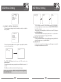
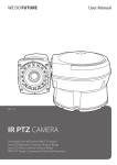
WE DO FUTURE
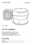
Ver. 1.2
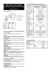
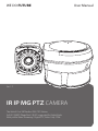
IR IP MG PTZ CAMERA
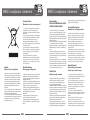
The World’s First 360°Endless PAN/ TILT Motion
Full HD(1080P) 2MegaPixel / IR LED supported for Night Mode
Multi-profile Video Streaming / Digital PTZ, Video Crop / IP68
User Manual
Contents
IR IP MG PTZ CAMERA
CONTENTS ····················································································································································································2
COMPONENTS ·············································································································································································2
WARNINGS & CAUTIONS ·························································································································································3
GENERAL FEATURES ··································································································································································6
PART NAMES ················································································································································································7
A. Basic Parts ··········································································································································································7
B. Connection Method ·······················································································································································8
INSTALLATION ·············································································································································································9
A. Ceiling Mount Bracket ···················································································································································9
B. Pole Stand ··········································································································································································11
C. Wall Mount Bracket ························································································································································13
D. Required System Specification ···································································································································15
E. Quick Installation Guide ·················································································································································15
QUICK OPERATING KEYS ·························································································································································20
DIAGNOSTIC ················································································································································································22
OSD MENU SETTING ·································································································································································23
A. OSD Menu Table ·······························································································································································18
B. Dome Set ············································································································································································· 19
C. Camera Set ·········································································································································································25
D. Preset Set ············································································································································································27
E. Auto Scan Set ····································································································································································28
F. Tour Set ················································································································································································29
G. Privacy Set ·········································································································································································30
H. Pattern Set ·········································································································································································31
I. Alarm Set ·············································································································································································33
J. Sector Set ···········································································································································································34
DIP SWITCHING SETTING ·······················································································································································40
A. ID Setting ··········································································································································································40
B. 485 Termination ······························································································································································41
C. Protocal ·············································································································································································41
D. Baud Rate Setting ··························································································································································41
TROUBLESHOOTING ·······························································································································································42
SPECIFICATION ·········································································································································································48
DIMENSIONS ·············································································································································································50
Components
IR IP MG PTZ CAMERA
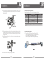
1. IR IP MG CAMERA 1SET
Warnings & Cautions
• If you fail to read this information and handle the product incorrectly, death or
serious injury may occur.
• The unit should be installed by the trained personnel.
• Switch off immediately if the product emits smoke or abnormal heat.
• Never install the product in area exposed to oil or gas.
• Never touch the power cord with wet hands.
• Clean only with dry cloth.
• Ensure that the product is not subjected to strong impacts and vibration.
CAUTION
RISK OF ELECTRIC SHOCK
DO NOT OPEN
CAUTION : TO REDUCE THE RISK OF ELECTRIC SHOCK,
DO NOT REMOVE COVER (OR BACK)
NO USER SERVICEABLE PARTS INSIDE. REFER SERVICING
TO QUALIFIED SERVICE PERSONNEL.
This symbol indicates that dangerous voltage consisting a
risk of electric shock is present within this unit.
This symbol indicates that there are important operating
and maintenance instructions in the literature accompanying
this unit.
2. MANUAL 1EA
002
IR IP MG PTZ CAMERA
003
WEEE Compliance statement
IR IP MG PTZ CAMERA
Français/French
Élimination de votre ancien appareil
1. Ce symbole, représentant une poubelle sur
roulettes barrée d'une croix, signifie que le
produit est couvert par la directive européenne
2002/96/EC.
2. Tous les produits électriques et électroniques
doivent être éliminés séparément de la chaîne
de collecte municipale des ordures, par l’
intermédiaire des installations de collecte
prescrites et désignées par le gouvernement ou
les autorités locales.
3. Une élimination conforme aux instructions
aidera à réduire les conséquences négatives et
risques éventuels pour l'environnement et la
santé humaine.
4. Pour plus d'informations concernant
l'élimination de votre ancien appareil, veuillez
contacter votre mairie, le service des ordures
ménagères ou encore le magasin où vous avez
acheté ce produit.
English
Deutsch/German
Disposal of your old appliance
Entsorgung von Altgeräten
1. When this crossed-out wheeled bin symbol
is attached to a product it means the product is
covered by the European Directive 2002/96/EC.
2. All electrical and electronic products should
be disposed of separately from the municipal
waste stream via designated collection facilities
appointed by the government or the local
authorities.
3. The correct disposal of your old appliance will
help prevent potential negative consequences for
the environment and human health.
4. For more detailed information about disposal of
your old appliance, please contact your city office,
waste disposal service or the shop where you
purchased the product.
1. Wenn dieses Symbol eines durchgestrichenen
Abfalleimers auf einem Produkt angebracht
ist, unterliegt dieses Produkt der europäischen
Richtlinie 2002/96/EC.
2. Alle Elektro- und Elektronik-Altgeräte müssen
getrennt vom Hausmüll über die dafür staatlich
vorgesehenen Stellen entsorgt werden.
3. Mit der ordnungsgemäßen Entsorgung des
alten Geräts vermeiden Sie Umweltschäden und
eine Gefährdung der persönlichen
Gesundheit.
4. Weitere Informationen zur Entsorgung
des alten Geräts erhalten Sie bei der
Stadtverwaltung, beim Entsorgungsamt oder
in dem Geschäft, wo Sie das Produkt erworben
haben.
004
WEEE Compliance statement
Italiano/Italian
IR IP MG PTZ CAMERA
zajmującym się utylizacją odpadów lub sklepem, w
którym produkt został kupiony.
RAEE: SMALTIMENTO DELLE VOSTRE
VECCHIE APPARECCHIATURE
Português/Portuguese
1. Quando il simbolo del “Cassonetto Barrato”
è apposto su un prodotto, significa che lo stesso
può ricadere nei termini previsti dalla Direttiva
Europea nr. 2002/96/EC in funzione dell’attuazione
definita dalla Legislazione dei singoli stati membri
dell’Unione Europea.
2. Tutti i prodotti elettrici ed elettronici dovrebbero
essere smaltiti separatamente dai rifiuti
municipali, tramite appositi contenitori, approvati
dall’Amministrazione Comunale o dalle Autorità
Locali.
3. Il corretto smaltimento delle vostre vecchie
apparecchiature, contribuirà a prevenire possibili
conseguenze di impatto negativo sull’ ambiente e
per la salute dell’uomo.
4. Per maggiori informazioni circa lo smaltimento
delle vostre vecchie apparecchiature, siete pregati
di contattare l’ufficio municipale della vostra città,
il servizio di smaltimento rifiuti o il punto vendita
nel quale avete acquistato il prodotto.
Polski/Polish
Utylizacja starych urządzeń
1. Kiedy do produktu dołączony jest niniejszy
przekreślony symbol kołowego pojemnika
na śmieci, oznacza to, że produkt jest objęty
europejską dyrektywą 2002/96/EC.
2. Wszystkie elektryczne i elektroniczne produkty
powinny być utylizowane niezależnie od odpadów
miejskich, z wykorzystaniem przeznaczonych do
tego miejsc składowania wskazanych przez rząd
lub miejscowe władze.
3. Właściwy sposób utylizacji starego urządzenia
pomoże zapobiec potencjalnie negatywnemu
wpływowi na zdrowie i środowisko.
4. Aby uzyskać więcej informacji o sposobach
utylizacji starych urządzeń, należy skontaktować
się z władzami lokalnymi, przedsiębiorstwem
Eliminação do seu antigo aparelho
1. Quando este símbolo de latão cruzado estiver
afixado a um produto, significa que o produto é
abrangido pela Directiva Europeia 2002/96/EC.
2. Todos os produtos eléctricos e electrónicos
devem ser eliminados separadamente da
coleta de lixo municipal através de pontos de
recolha designados, facilitados pelo governo ou
autoridades locais.
3. A eliminação correcta do seu aparelho antigo
ajuda a evitar potenciais consequências negativas
para o ambiente e para a saúde humana.
4. Para obter informaçõs mais detalhadas acerca
da eliminação do seu aparelho antigo, contacte as
autoridades locais, um serviço de eliminação de
resíduos ou a loja onde comprou o produto.
Español/Spanish
Cómo deshacerse de aparatos
eléctricos y electrónicos viejos
1. Si en un producto aparece el símbolo de un
contenedor de basura tachado, significa que éste
se acoge a la Directiva 2002/96/EC.
2. Todos los aparatos eléctricos o electrónicos se
deben desechar de forma distinta del servicio
municipal de recogida de basura, a través de
puntos de recogida designados por el gobierno o
las autoridades locales.
3. La correcta recogida y tratamiento de los
dispositivos inservibles contribuye a evitar riesgos
potenciales para el medio ambiente y la salud
pública.
4. Para obtener más información sobre cómo
deshacerse de sus aparatos eléctricos y
electrónicos viejos, póngase en contacto con su
ayuntamiento, el servicio de recogida de basuras o
el establecimiento donde adquirió el producto.
005
General Features
IR IP MG PTZ CAMERA
• FULL HD IR PTZ has been designed unique and strong with high quality for security applications
that demand the very high performance both day and at night time.
• Rated to an industry leading IP68, the vandal resistant aluminum camera housing is suitable for
installation in the harshest of environments.
• Surveillance with optimum picture is possible owing to filter changeable Day & Night function and
DSS function.
• Auto-IR cut filter removable function is the auto-controlling operation such as color picture plus
infrared cut filter during the day and black and white picture plus filter elimination at night.
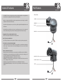
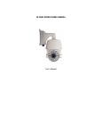
Part Names
IR IP MG PTZ CAMERA
A. Basic Parts
CAMERA
MAIN BODY
IR LED
BASE BODY
THE WORLD'S FIRST 360° ENDLESS PAN/TILT MOTION
• IR PTZ camera adopted the world's first 360° endless Pan / Tilt.
PAN / TILT TORQUE COMPENSATION
• Pan / Tilt Torque vibration sensor keeps the Pan / Tilt Motor securely in place during strong winds.
AUTO LED PULSE CONTROL BY DISTANCE RANGE
• It automatically controls the pulse of LED electric current which is consumed Most depending on
distance range so that it produces 2 times better LED Brightness with same amount of electric
current as others.
VARIOUS SURVEILLANCE FUNCTIONS
• Auto Scan repeats pan and tilt between two preset positions with different speed and dwell time.
• 8 Group Tour up to 8 Programmable Group tours available and each group is consisting up to 60
presets step with different speed and dwell time with 16 characters.
• 165 programmable preset positions are available with 16 characters.
• 8 Patterns up to 8 programmable user-defined patters are available with 16 characters and each
one is consisting 50 seconds, total 480.
• 8 Sectors up to 8 programmable user-defined sectors are available with 16 characters.
• 4 Alarm input and 2 relay out up to 4 alarms and 2 relay out available to match with preset, tours,
patterns.
006
DIP SWITCH COVER
MOUNT HOLE (M4 x 16 - 4EA)
CABLE
007
Part Names
IR IP MG PTZ CAMERA
Installation
IR IP MG PTZ CAMERA
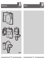
A. Ceiling Mount Bracket
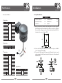
B. Connection Method
CONTENTS
ⓐ Explanation
Color
YELLOW
WHITE
BLUE
BROWN
SKY BLUE
PINK
ORANGE
GRAY
VIOLET
RED
GREEN
BLACK
USE
LED RED
LED GREEN
LED +
LED D
C
LAN RXB
A
LAN RX+
LAN TXLAN TX+
1. CEILING MOUNT BRACKET 1EA
4. SPRING WASHER Ø4
5EA
2. SET ANCHOR BOLT (W5/9) 4EA
5. WRENCH (3mm)
4EA
3. SCREW M4 x 16
5EA
6. MANUAL
A-1. When you install IR PTZ Camera on the ceiling, make 4 holes at the edge with
Ø13 in diameter and 37mm in depth. If you want to connect the cables from
the inside of the ceiling, also make a ole for the cables with about Ø30~50 in
diameter in the center of 4 edges. (FIG.1)
ⓑ Explanation
Color
TRANSPARENT PINK
BNC
USE
Video Cable
ⓐ
ⓒ Explanation
Color
YELLOW
BROWN
RED
WHITE
GRAY
VIRMILION
VIOLET
PINK
PASTEL GREEN
BLACK
BLUE
GREEN
PHONE JACK RED
PHONE JACK WHITE
ⓒ
(AWG#20)
USE
AUX 1-A
AUX 1-B
AUX 2-A
AUX 2-B
GND
ALARM 1
ALARM 2
ALARM 3
ALARM 4
GND
RS-485 D+
RS-485 DMIC LINE IN
LINE OUT
ⓑ
ⓓ
A-2. Connect the Ceiling Mount Bracket to the Camera with 4 pieces of M4X16
screws and spring washer. (FIG.2)
A-3. Connect the Safety wire of the Camera to the Bracket. In order to avoid
getting entangled in the Camera, fasten the Safety wire to the bracket with
Cable tie. (FIG.3)
(M4 x 16 - 4EA)
ⓓ Explanation
Color
008
RED
USE
+ DC 24
WHITE
BLACK
GND
N/C
009
Installation
IR IP MG PTZ CAMERA
A-4. When you want to connect the cables from the inside of ceiling, pass the
cables through the ceiling. When you want to connect the cables from the
outside of ceiling, remove the hole cap from the side of the bracket and pass
the cables through the hole.
Installation
IR IP MG PTZ CAMERA
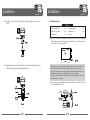
B. Pole Stand
CONTENTS
1. POLE STAND
1EA
5. SCREW M4 x 16
2. BOLT & NUT M10 4EA
6. SPRING WAHGER Ø45EA
5EA
3. FLAT WASHER
4EA
7. WRENCH (3mm)
4. SPRING WASHER Ø10 4EA
8. MANUAL
1EA
B-1. When you install IR-PTZ Camera on the pole, make 4 holes at edge with Ø13
in diameter and 37mm in depth.
Make also a hole for the cables with about Ø30~50 in diameter in the
bottom center of the bracket. (FIG.6)
A-5. Install 4 pieces of Anchor bolt in the holes at the edge and tight enough
with Nuts. (FIG.4)
B-2. Pass the cables of the camera through the inside of Pole Stand and connect
the Camera to the Pole Stand with pieces of M4*16 screws. (FIG.7)
B-3. Connect the Safety Wire of the camera to the bracket.
In order to avoid getting entangled in the camera, fasten the Safety wire to
the bracket with Cable Tie. (FIG.8)
A-6. Connect the cables referring to the page 8. (FIG.5)
(M4 x 16 - 4EA)
010
011
Installation
IR IP MG PTZ CAMERA
B-4. Install 4 pieces of Anchor bolt in the Ø13 holes at the edge and connect the
cables.
Installation
IR IP MG PTZ CAMERA
C. Wall Mount Bracket
CONTENTS
1. WALL MOUNT BRACKET
1EA
4. SPRING WASHER Ø4 5EA
2. SET ANCHOR BOLT (W5/6) 4EA
5. WRENCH (3mm)
1EA
3. SCREW M4 x 16
5EA
6. MANUAL
C-1. When you install IR PTZ Camera on the wall, make 4 holes at the edge with
Ø13 in diameter and 37mm in depth and install 4 pieces of Anchor bolt in
the Ø13 holes at the edge. (FIG.11)
B-5. Adjust the Camera and Pole Stand to M10 x 45 Bolt and Flat Washer, Spring
Washer. And then tight enough with Nuts. (FIG.10)
• If you want to connect the cables from the inside of the wall, also ake a hole
for the cables with about Ø30~50 in diameter in the center of 4 edges.
• In order to avoid the impact of the Camera and Bracket when moving, set
and drill in the long side as length and the short side as height.
• Check also if the long side of the Bracket sets as length and the short side
of the Bracket sets as height.
C-2. Connect the Camera to Wall Mount Bracket with 4 pieces of M4 x 16 screws
and Spring Washer. (FIG.12)
(M4 x 16 - 4EA)
(M10 x 45 - 4EA)
012
013
Installation
IR IP MG PTZ CAMERA
C-3. Connect the Safety wire of the Camera to the Bracket. In order to avoid
getting entangled in the Camera, fasten the Safety wire to the bracket with
Cable tie. (FIG.13)
Installation
IR IP MG PTZ CAMERA
D. Required System Specification
Required Specification of PC for Camera Configuration & Control.
Class
CPU
RAM
Graphic Card
LAN Card
OS
Web Browser
Recommendation
Pentium-4 3Ghz
1GB
Higher than ATI Chip-Set based 64M
Higher than 100Mbps
Windows XP
Higher than Internet Explorer 6.0
Remark
1600x1200(UXGA)
· Operating Systems supported : Windows 2000 Professional, Windows XP /
Vista / 7.
C-4.When you want to connect the cables from the inside of wall, pass the cables
through the wall. When you want to connect the cables from the outside of
wall, remove the hole cap from the side of the bracket and pass the cables
through the hole.
C-5.Install 4 pieces of Anchor bolt in the holes at the edge and tight enough
with Nuts. (FIG. 13)
E. Quick Installation Guide
E-1. Connect PC and PTZ Camera to Network Device (HUB)
a. Prepare a PC which needs to be connected to Network.
b. Connect PC(or Lab-Top) with Product as FIG. 1.
AC Power is applied to the Product through AC Adaptor.
AC Adaptor
LAN Switch
FIG. 1
C-6.Connect the cables referring to the page 8. (FIG.14)
014
015
Installation
IR IP MG PTZ CAMERA
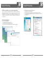
E-2. IP PTZ Camera Network Configuration using IP Installer
Run the CD and Install IP Installer included in CD. Once install IP Installer,
“WinPcap” will be installed. If not install “WinPCap”, IP Installer won’t operate.
a. Run IP Installer > Select Network Adaptor > Click OK.
b. If Configuration Window open, Click ① > Double Click the relevant
product at ② > Fill in ④ > Configure ⑤ > Fill in ⑥ or ⑧.
c. If Configuration is completed, Click Set Button ⑨ to apply Configuration.
d. Access to Camera Admin Page by clicking ⑩.
③
①
⑨
⑩
②
Installation
IR IP MG PTZ CAMERA
· If you click each field of ③, you can use sort function. For the detail, refer to
IP Installer Manual.
You can select the most appropriate LAN, ADSL, Static/Dynamic IP per Cable
to user’s circumstance via ⑤ menu. In case of selecting Dynamic(Automatic)
IP, ⑥ menu will be deactivated, In case of ADSL, please insert User Name
and Password provided from ISP in each field of ⑧.
· For DDNS Service
Insert mgmt.net-video.net in ⑦ > Please configure to be registered on
DDNS by marking Check Box.
You can use after Member Registration on Management Site "http://www.
net-video.net/".
E-3. Remote Connection to IP Camera
a. Connection via Web Viewer
Web View is the simplest method to connect to product via internet
explorer. Once you insert "http://IP_address:HTTP_port number" into
Internet Explorer, you can access to the relevant product.
⑤
④
⑦
⑥
⑧
· For the use of Web Viewer, Active-X module should be installed.
If internet access is available, you can download it by accessing Camera or if
you install NVR-Pro, Active-X module will be installed together.
• For the Network Configuration of IP PTZ Camera, IP Installer should be higher
than 3.0.1 Version.
For the Window 7 User,”WinPCap” should be higher than 4.0 Version.
016
017
Installation
IR IP MG PTZ CAMERA
Admin Tool Access ButtonAdmin Tool Access Button
Basic Control Key
Installation
IR IP MG PTZ CAMERA
b. Connection via NVR-Pro
NVR-Pro is a CMS program to connect several IP Cameras and/or Video
Servers. Once you run NVR-Pro after installing on the remotely located PC,
you can monitor real-time Video/Audio on the PC by accessing to IP Camera
via IP Address assigned to each IP Camera. For the access to Product by
using NVR-Pro, you have to configure all required information at NVR-Pro.
For the detail, please refer to [NVR-Pro User Manual].
Video Crop Menu
[ Web Viewer Connection ]
[ NVR-Pro ]
E-4. Initial Configuration by connecting Admin Mode
All Parameters of IP PTZ Camera is initially set as factory default. So you
must change them with appropriate value to your network configuration by
accessing via Admin Tool. Admin Tool Access Method is as below.
Http://[IP Address]:[HTTP Port No.]/ admin.htm
018
019
Quick Operating Keys
IR IP MG PTZ CAMERA
The IR Camera supports Pelco D/P Protocols
The default setting of the IR Camera is Pelco D/P(Auto Detection) with 2400bps
(Baud rate).
[PELCO D/P PROTOCOLS]
The comprehensive feature set of the camera is available from Pelco Compatible
controllers via quick operation keys as defined below.
1 ~ 64 + preset and 100 ~ 200 + preset are used for normal user presets.
Presets 65 ~ 99 + are reserved for special functions.
For Example, to enter OSD MENU, press the button 95 + Preset.
<Quick Operation Key Table 1>
Number
1 ~ 64, 100 ~ 200 + PRESET
65 + PRESET
66 + PRESET
70 + PREST
71 ~ 78 + PREST
81 ~ 88 + PREST
91 + PREST
92 + PREST
93 + PREST
94 + PREST
95 + PREST
96 + PREST
97 + PREST
98 + PREST
99 + PREST
Note
Preset
Preset Status
Auto Scan
VIB CORR
Group Tour
Pattern
Zero Position
Freeze
BLC
Day/Night
OSD
Focus Adjust
Alarm
AUX1
AUX2
Quick Operating Keys
• 65 + Preset
Preset Status is displayed, to remove this screen, Press Focus Near button.
• 92 + Preset
This feature freezes the current live image during tour, auto scan or pattern
operation.
When you press 92+Preset button, the image freezes but the camera is still
working as operation such as tour, pattern or auto scan.
To return to normal images, press 92+Preset button again
• This feature is operated by preset number but not included in OSD main menu.
• Due to Zoom camera module. OSD Menu not provides every feature.
In this case, “Not available” is displayed on the monitor.
Function
Executing Preset 1 ~ 64, 100 ~ 200
Display Preset Status
Executing Auto Scan
Selectable On / Off in picture Stabilization Function
Executing Group Tour #1 ~ #8
Executing Pattern #1 ~ #8
Searching Pan / Tilt Zero Position
Select Freeze image when camera is working
Selectable On / Off BLC function
Selectable Day / Night / Auto Mode
Entering OSD Main Menu
Focus adjust
Selectable Enable / Disable all alarms
Selectable On / Off Aux1
Selectable On / Off Aux2
<Quick Operation Key Table 2>
Number
Tilt Up / Down
Pan Left / Right
Focus Near
Focus Far
Zoom Tele
Zoom Wide
Function
Sub menu cursor moves up / down
Enter to the sub menu or status change or decrement
Using for enter key when user select YES or NO
Using for function changing keys when set coordinate
Status cursor to the right
Status cursor to the left
020
IR IP MG PTZ CAMERA
021
Diagnostic
IR IP MG PTZ CAMERA
Whenever the IR Camera is power on, a standard diagnostic is operated.
OSD Menu Setting
A. OSD Menu Table
MAIN MENU
CAMERA ID
BAUD RATE
: 001
: 2400BPS
PAN ORIGIN
TILT ORIGIN
TX CONNECTION
CAMERA COMM
WAITING............
TEST OK
TEST OK
TEST OK
TEST OK
DOME SETUP
CAMERA SET
PRESET
AUTO SCAN
TOUR
PRIVACY
PATTERN
ALARM
SECTOR
EXIT
• If “Not Tested” is displayed in the test.
- The result which is not received any signal from DVR or controller.
- Wrong connecting way such as the protocol, baud rate or RS-485
connection.
The use may check the install way carefully.
PRIVACY NO
DISPLAY
ACTION
SAVE
EXIT
: 01
: ON/OFF
: MOVE / ADJUST
PATTERN SET
PATT NO
PATT TITLE
DATE FILL
SAVE
EXIT
: 01
: PATTERN 01
: 100%
If all the above Tests are OK, “NOW EEPROM CHECKING” and “ALL DATA
INITIALIZING” is displayed and the camera is ready to operate.
022
: CAM 1
: OFF
: 150℃
: FAST
: DISABLE
: ENGLISH
CAMERA SET
FLICKER
SHUTTE-SPD
APERTURE
DZOOM
WB MODE
BLC
D/N MODE
DSS MODE
[NEXT PAGE]
EXIT
: OFF / ON
: 1/50
: 10
: OFF / ON
: AWB MODE
: OFF / ON[BLC / WDR]
: AUTO
: OFF / ON
CAMERA SET
HR MODE
: OFF / ON
DNR MODE
: 05
RES. MODE
: 1920x1080@30P
[PREVIOUS PAGE]
DOME SET
[SYSTEM SET]
SYSTEM LOCK
: OFF
[PASSWORD]
[OSD DISPLAY]
[SYSTEM STATUS]
[INITIALIZATION]
[PREVIOUS PAGE]
SYSTEM SET
FLIP STATUS
MOTOR TORQUE
RECOVER ORIGIN
D/N LEVEL
TEMPERATURE
[PREVIOUS PAGE]
: NOMAL
: LOW
: ON
: 08
: CELSIUS
OSD DISPLAY
CAMERA ID
PRESET ID
SECTOR ID COORDINATE
[PREVIOUS PAGE]
: ON / OFF
: ON / OFF
: OFF / ON
: ON / OFF
PRESET SET
PRESET NO
PRESET ID
PAN : XXX.X
FREEZE MODE
FREEZE ALL
SAVE
EXIT
: 01
: PRESET 01
TITL : XX.X
: OFF
: OFF
ALARM SET
D. Camera Comm. Test
Camera communication is also checked.
OK should be displayed in these four tests before installation.
DOME SET
CAMERA ID
HOME POS
MANUAL SPEED ZOOM SPEED ALARM
LANGUAGE
[NEXT PAGE]
SAVE AND EXIT
EXIT
PRIVACY SET
A. PAN Origin Test
Zero point of Pan is Located during the Panning test.
B. Tilt Origin Test
Zero point of Tilt is Located during the Tilt Test
C. TX Connection Test
Wait for 60 seconds for TX Connection Test.
During 60 seconds, the camera is must received a signal by any control
equipment as DVR or controller.
Then OK is displayed then automatically verifying TX Connection Test
IR IP MG PTZ CAMERA
ALARM NO
ALARM INPUT
ALARM ACT
AUX ACT
SAVE
EXIT
: 01
: OFF / ON / NC
: 001
: BLK
AUTO SCAN SET
START ANGLE
END ANGLE
DIRECTION
ENDLESS
SPEED
DWELL TIME
SAVE AND EXIT
EXIT
: XXX.X.XXX.X
: XXX.X.XXX.X
: CW
: OFF / ON
: 10°/S
: 03
TOUR SET
SECTOR
SECTOR NO
SECTOR ID
SECTOR START
SECTOR END
SAVE
EXIT
: 01
: SECTOR01
: XXX.X.XX.X
: XXX.X.XX.X
TOUR NO
TOUR TITLE
TOUR STEP
PRESET NO
DWELL TIME
SPEED
SAVE
EXIT
: 01
: TOUR 01
: 01
: BLK
: 03
: 200°/S
023
[SYSTEM STATUS]
PROTOCOL
: PELCO D/P
BAUD RATE
: 2400BPS
FIRMWARE VER : 2.00a
UPGRADEDDATE : 11.01.11
CAMERA MODULE: EX1020
[PREVIOUS PAGE]
[INITIALIZATION]
[TOUR CLEAR]
[PRESET CLEAR]
[SECTOR CLEAR]
[PRIVACY CLEAR]
[PATTERN CLEAR]
[LOAD OPTIMIZED DEFAULT]
[PREVIOUS PAGE]]
OSD Menu Setting
IR IP MG PTZ CAMERA
To enter OSD Menu, press the button 95+Preset then OSD Main Menu is
displayed.
MAIN MENU
DOME SETUP
CAMERA SET
PRESET
AUTO SCAN
TOUR
PRIVACY
PATTERN
ALARM
SECTOR
EXIT
• Use the joystick up down to move the position and left right to make selection.
B. Dome Setup
To enter dome setup, use the joystick right to move when cursor on dome setup.
DOME SET
CAMERA ID
HOME POS
MANUAL SPEED ZOOM SPEED ALARM
LANGUAGE
[NEXT PAGE]
SAVE AND EXIT
EXIT
: CAM 1□□□□□□□□□
: OFF
: 150℃
: FAST
: DISABLE
: ENGLISH
B-1. DOME SET - CAMERA ID
To set camera name, and select a title of up to 16 characters using left or
right direction keys or joystick. Press ZOOM TELE button to move to the next
character from left to right direction and ZOOM WIDE button to move to the
next character from right to left direction. (Space displays when □ appears.)
B-2. DOME SET - HOME POS
This is for Home Position, basically, including the Recover. On ON, it would
be indicated the number [Relevant function], number is for time and
[Relevant function] is that what operation product will be working on.
You can set up the time using the Joystick Left/Right, it should be showed
up on the Left of Menu if you press the Focus Far Key. In case of “[ ]”, possible
to change into other one as you want and come out from “[ ]” after vanish.
024
OSD Menu Setting
IR IP MG PTZ CAMERA
- Set time : 15~90 (Each 5)
- Set article : [AUTO] - RECOVER operation.
[PRST1]-[PRST8] – PRESET1 ~ PRESET8 OPERATION.
[TOUR1] ~ [TOUR8] – TOUR1 ~ TOUR8 OPERATION.
[PATT1] ~ [PATT8] – PATTERN1 ~ PATTERN8 OPERATION
[SCAN] – AUTOSCAN OPERATION.
B-3. DOME SET - MANUAL SPEED
Manual speed of Pan / Tilt is selectable from 100˚/sec up to 200˚/sec.
The default setting is 150˚/sec.
B-4. DOME SET - ZOOM SPEED
Move joystic right or left direction is selectable from SLOW ~ FAST.
The default setting is FAST.
B-5. DOME SET - ALARM
You must enable the alarms for them to operate. The default setting is
disabled.
This function can be recalled by pushing 97+preset button.
B-6. DOME SET – LANGUAGE
Multiple languages are selectable here including English, Italian and Polish.
The default setting is ENGLISH.
B-7. DOME SET - [NEXT PAGE]
DOME SET
[SYSTEM SET]
SYSTEM LOCK
[PASSWORD]
[OSD DISPLAY]
[SYSTEM STATUS]
[INITIALIZATION]
[PREVIOUS PAGE]
: OFF
025
OSD Menu Setting
IR IP MG PTZ CAMERA
B-7-1. DOME SET - [NEXT PAGE] -SYSTEM SET
To enter system set, use the joystick right to move when cursor on system set.
- Flip status available and the default setting is NORMAL.
Move joystick right or left direction is for selecting NORMAL or REVERSE.
- Motor torque available and the default setting is LOW.
Move joystick right or left direction is for selecting LOW or MIDDLE or HIGH.
- Recover Origin is for correct when both of PAN and TILT are warped by
impact.
On ON, it should be operated, on OFF, it's not.
- D/N Level is selectable 0 to 15. The default setting is 08.
- Temperature available and the default setting is CELSIUS.
Move joystick right or left direction is for selecting CELSIUS or FAHRENHEIT.
OSD Menu Setting
SYSTEM SET
: NOMAL
: LOW
: ON
: 08
: CELSIUS
B-7-2. DOME SET - [NEXT PAGE] -SYSTEM LOCK
All stored dome settings can be password protected to prevent
unauthorized changes. In order to enter [PASSWORD] page, the system lock
status must firstly be set as ON. The default setting is OFF.
B-7-3. DOME SET - [NEXT PAGE] -[PASSWORD].
To enter this page to set a password. move joystick or pan key in the right
direction.
The password must be set by preset number from 001 to 255 (Default 99).
ENTER PASSWORD
BY ENTERING PRESET CODE
PASSWORD ***
CONFIRM ***
026
Enter any number from 001~255 on the password blank area and again on
the confirm blank area.
Then “CONFIRMED” is displayed on the monitor and the menu will go back
to the previous age automatically.
ENTER PASSWORD
BY ENTERING PRESET CODE
PASSWORD ***
CONFIRM *** CONFIRMED
ENTER PASSWORD
BY ENTERING PRESET CODE
PASSWORD ***
CONFIRM *** NOT CORRECT
[CONFIRMED]
FLIP STATUS
MOTOR TORQUE
RECOVER ORIGIN
D/N LEVEL
TEMPERATURE
[PREVIOUS PAGE]
IR IP MG PTZ CAMERA
[CANCELLED]
If you press an incorrect number between PASSWORD and CONFIRMED,
“CANCELLED” is displayed on the monitor when you press FOCUS NEAR key.
“CANCELLED” will be displayed on the monitor, it goes to previous page.
• When a password has been set, the operator must enter the correct
password in order to enter OSD MAIN MENU, or to change any of the
domes configuration data.
• If you set a password you must ensure that it does not get lost. If this
happens the dome must be returned for workshop repair.
B-7-4. DOME SET - [NEXT PAGE] - [OSD DISPLAY]
The camera ID setting defines whether the camera OSD display is displayed
or switched off.
OSD DISPLAY
CAMERA ID
PRESET ID
SECTOR ID COORDINATE
[PREVIOUS PAGE]
: OFF
: OFF
: OFF
: ON
B-7-5. DOME SET - [NEXT PAGE] - [SYSTEM STATUS]
This page shows the information of this camera.
- Protocol and baud rate are shown due to the dip switch setting
- Firmware version and upgraded date will change if upgraded.
- Camera module is setting as follows.
027
OSD Menu Setting
IR IP MG PTZ CAMERA
OSD Menu Setting
[SYSTEM STATUS]
LOAD OPTIMIZED DEFAULT
ARE YOU SURE? YES NO
PROTOCOL
: PELCO D/P
BAUD RATE
: 2400BPS
FIRMWARE VER
: 2.00
UPGRADEDDATE : 11.01.11
CAMERA MODULE : EX1020
[PREVIOUS PAGE]
B-7-6. DOME SET - [NEXT PAGE] - [INITIALIZATION]
To clear the current settings select the item that you wish to reset back to
factory defaults.
[INITIALIZATION]
[TOUR CLEAR]
[PRESET CLEAR]
[SECTOR CLEAR]
[PRIVACY CLEAR]
[PATTERN CLEAR]
[LOAD OPTIMIZED DEFAULT
[PREVIOUS PAGE]]
To clear the memorized data. move the joystick or pan right key until the
cursor is on the required item.
TOUR CLEAR
ARE YOU SURE? YES NO
NOW EEPROM
CHECKING
ALL DATA
INITIALIZING
- To Clear all data and return to factory defaults, move the joystick right or
press the pan light key to when the cursor is at [LOAD OPTIMIZED DEFAULT]
to enter the next page.
- Move joystick or the pan right key so that the cursor is over YES, then press
the FOCUS NEAR button.
“ALL DATA INITIALIZING” is then displayed for about 5~7 seconds and then
the menu is returned to the previous page automatically.
B-8. DOME SET - SAVE AND EXIT
To saving the memorized data and escape this page, move joystick to the
right direction when cursor is at SAVE AND EXIT.
B-9. DOME SET - EXIT
In order not to save any data and wants to escape this page, move joystick
to the right direction when cursor is at EXIT.
TOUR CLEAR
Press FOCUS NEAR button when the cursor is at YES in order to clear
memorized data.
Then each item such as tour, preset, and sector will flicker for about 2 ~ 3
seconds.
After this process, the menu is returned to the previous page.
• Use the above method for [PRESET CLEAR], [SECTOR CLEAR],[PRIVACY
CLEAR], [PATTERN CLEAR].
028
IR IP MG PTZ CAMERA
029
OSD Menu Setting
IR IP MG PTZ CAMERA
C. Camera Set
CAMERA SET
FLICKER
SHUTT-SPD
APERTURE
DZOOM
WB MODE
BLC
D/N MODE
DSS MODE
[NEXT PAGE]
EXIT
CAMERA SET
: OFF
: 1/50
: 10
: OFF / ON
: AWB MODE
: OFF / ON[BLC / WDR]
: AUTO
: OFF / ON
HR MODE
: OFF / ON
DNR MODE
: 05
RES. MODE
: 1920x1080@30P
[PREVIOUS PAGE]
C-1. CAMERA SET - FLICKERLESS
The flickerless feature has options of 50Hz and 60Hz.
The default setting is OFF (NTSC : 60Hz / PAL : 50Hz).
The flickerless mode only needs to be set when there is a mismatch between
the power frequency and camera sync rate. The default setting is OFF.
C-2. CAMERA SET - SHUTTER-SPD
It is for set up the Shutter Speed of camera.
•Default value is Auto and it can be changed into other one using the
Joystick Left/Right of Controller.
- Change to turn : Full Auto → Manual
- Auto : Changed according to light level automatically.
- Manual : It can be changed into other one using the Focus Far Key of
controller and on ON the DSS (Digital Slow Shutter), it should be set up 1/1
to 1/10,000, on OFF, 1/50(1/60)~1/10,000.
C-3. CAMERA SET - APERTURE
Aperture correction enhances the picture details and sharpness by
increasing the gain of the camera.
Increase the value to sharpen the image, decrease to soften it the default
setting is 10. (The aperture level is from 01 ~ 15.)
C-4. CAMERA SET - D ZOOM
Digital zoom is enabled to apply when the zoom lens has reached its
maximum optical zoom in capability. The default setting is OFF.
C-5. CAMERA SET - WB MODE
White balance functions has 4 modes and may need to be changed
depending on the situation.
• AWB Mode : 3,200ºK to 6,500ºK (Default)
• Indoor : up to 3,200ºK
• Outdoor : up to 5,800ºK
030
OSD Menu Setting
IR IP MG PTZ CAMERA
C-6. CAMERA SET - BLC (Back Light Compensation)
From simple ON / OFF setting to user friendly BLC status indication [BLC]
status with control of controller by "FOCUS FAR KEY"(" " signal appeared)
With the control of joystick on controller by LEFT / RIGHT, setting change of
[BLC] / [WDR] is available.
Setting change completed by pressing FOCUS FAR KEY.(" " signal disappeared.)
This function can be recalled by pushing 93 + Preset button.
C-7. CAMERA SET - D/N MODE
The dome camera can operate in day / night mode and will switch
depending on lighting conditions. Alternatively it can be forced into color
only mode.
The default setting is AUTO MODE. This function can be recalled by pushing
94 + Preset button.
C-8. CAMERA SET - DSS MODE (DIGITAL SLOW SHUTTER)
If digital slow shutter is enabled the exposure time of the camera is
increased, thus allowing more light to be collected and improving low light
response.
This setting should not be enabled if the dome is touring at night or fast
moving objects are likely to be in the scene as smearing is also increased.
The default setting is OFF.
C-9. CAMERA SET - [NEXT PAGE] - HR MODE
Images with a high resolution can be obtained using a newly developed
DSP for improved pictur quality. The default setting is OFF.
• OFF : 530TV Lines
• ON : 550TV Lines
C-9-1. CAMERA SET - [NEXT PAGE] - DNR MOED
It enables noise reduction digitally.
It sets the noise reduction rate using LEFT / RIGHT key of CONTROLLER
JOYSTICK [OFF, 1~5]. The default setting is OFF
C-9-2. CAMERA SET - [NEXT PAGE] - RES. MODE
The current resolution will be displayed on the screen.
031
OSD Menu Setting
IR IP MG PTZ CAMERA
OSD Menu Setting
IR IP MG PTZ CAMERA
E. Auto Scan Set
D. Preset Set
PRESET SET
PRESET NO
PRESET ID
PAN : XXX.X
FREEZE MODE
FREEZE ALL
SAVE
EXIT
: 01
: PRESET 01
TITL : XX.X
: OFF
: OFF
D-1. PRESET - PRESET NO
Up to 165 preset positions are available.
Use the joystick or pan left / right keys to select the number.
D-2. PRESET - PRESET ID
To create preset titles use the joystick or pan left / light keys to navigate the
menu.
The ZOOM TELE button moves to the next character from left to right and
ZOOM WIDE button moves to the next character from right to left. (Space
displays when □ appears.)
D-3. PRESET - PAN : XXX.X TILT : XX.X
Preset FOCUS FAR button in order to set preset position then, use the
joystick or pan left / right keys to the position where memorized preset
number is needed.
Then press FOCUS FAR button again after setting a preset location.
D-4. FREEZE MODE : On Preset, you make a decision whether you get it move or
stop.
On ON, Freeze Preset can be working on.
D-5. FREEZE ALL : You can set it up into ON / OFF, on ON, Freeze all should be
working on.
D-6. PRESET - SAVE
Move the joystick right or press the pan right key when the cursor is at SAVE
and then the cursor will be located on Preset ID for the continuous preset
No. setting.
D-7. PRESET – EXIT
To escape this page, move joystick to the right direction.
032
66 + Preset button is working as AUTO SCAN after setting.
AUTO SCAN SET
START ANGLE
END ANGLE
DIRECTION
ENDLESS
SPEED
DWELL TIME
SAVE AND EXIT
EXIT
: XXX.X.XXX.X
: XXX.X.XXX.X
: CW
: OFF
: 10°/S
: 03
E-1. AUTO SCAN - START ANGLE
To set the start position, press FOCUS FAR button then move the dome to
the required start position. Press FOCUS FAR button again is to escape.
E-2. AUTO SCAN - END ANGLE
To set the end position, press FOCUS FAR button then move the dome to the
required end position. Press FOCUS FAR button again is to escape.
E-3. AUTO SCAN - DIRECTION
Auto Scan directions are available as CW or CCW.
• CW : Clock wise direction. [Default]
• CCW : Count Clock Wise Direction.
E-4. AUTO SCAN - ENDLESS
Auto Scan can be set to endless rotation by enabling the endless option.
The default setting is OFF.
E-5. AUTO SCAN – SPEED
The scan speed can be programmed from 05°/S up to 35°/S.
The default setting is 10°/S.
E-6. AUTO SCAN - DWELL TIME
The dwell time at the start and end points can be programmed from 1
second to 30 seconds. The default setting is 03 seconds.
E-7. AUTO SCAN - SAVE AND EXIT
To save the memorized data and escape this page, move the joystick right or
press the pan right key when the cursor is at SAVE AND EXIT.
E-8. AUTO SCAN - EXIT
To escape this page, move joystick to the right direction.
033
OSD Menu Setting
IR IP MG PTZ CAMERA
OSD Menu Setting
F. Tour Set
G. Privacy Set
8 Programmable tours can be set and each tour can have up to 64 preset steps.
After setting up the tours the 71 ~ 78+Preset buttons launch group tours #1 ~ 8.
8 Privacy masking zones can be set.
IR IP MG PTZ CAMERA
PRIVACY SET
TOUR SET
TOUR NO
TOUR TITLE
TOUR STEP
PRESET NO
DWELL TIME
SPEED
SAVE
EXIT
: 001
: TOUR 01□□□□□□□□□
: 01
: 01
: 03
: 200°/S
F-1. TOUR SET - TOUR NO.
Up to 8 group tours can be programmed.
F-2. TOUR SET - TOUR TITLE
To set a tour title, use the joystick left / right or pan left / right keys.
Each title can have up to 16 characters. Press ZOOM TELE button to move
the next character from left to the right and ZOOM WIDE button to move the
next character from right to left. (Space displays when □ appears.) The tour
title is not displayed on the monitor and is only for the reference of user.
F-3. TOUR SET - TOUR STEP
Each tour group consists of up to 60 preset steps with different dwell time
and speed.
It is possible to match any preset # for any tour step.
F-4. TOUR SET- PRESET NO.
For each tour step it is possible to select any preset number up to 64.
The default setting is BLK.
F-5. TOUR SET - DWELL TIME
Dwell time can be programmed from 1-99 seconds.
The default setting is 03 seconds.
F-6. TOUR SET – SPEED
Each tour step can be set with a different speed up to 200°/S.
F-7. TOUR SET - SAVE
To save the memorized data and escape this page, move the joystick right or
press the pan right key when cursor is at SAVE.
F-8. TOUR SET - EXIT
To escape this page, move joystick to the right direction.
034
PRIVACY NO
DISPLAY
ACTION
SAVE
EXIT
: 01
: OFF
: MOVE
G-1. PRIVACY SET - PRIVACY NO.
Up to 8 privacy masking zones can be set.
G-2. PRIVACY SET - DISPLAY
Move the joystick right or left or press pan right / left to set ON in order to
show the selectable block in the center of the monitor. This block appears as
a translucent square with blue color when set ON. The default setting is OFF.
G-3. PRIVACY SET - ACTION (MOVE / ADJUST)
To set the blocking area, press FOCUS FAR button when MOVE MODE is
displayed.
Then use the joystick or pan keys to the user defined area in order to set the
blocking area.
Then press FOCUS FAR button again to escape from Move mode.
To adjust the size of the blocking area, move the joystick or use the pan keys
when the cursor is on ACTION. After it has changed to ADJUST MODE, press
FOCUS FAR button in order to adjust the size of the blocking area. The size of
the blocking area can be adjusted by using joystick up / down or left / right
or the pan and tilt keys.
After adjusting the size of the blocking area, press FOCUS FAR button to
escape the ADJUST mode.
• ADJUST : You can change the masking size by using the joystick or pan
keys.
• MOVE : You can move the masking area by using the joystick or pan keys.
(Default)
035
OSD Menu Setting
IR IP MG PTZ CAMERA
G-4. PRIVACY SET - SAVE
After setting the privacy masking zone, to save the data, move the joystick
right or pan right key when the cursor is on SAVE.
After saving the data, the cursor moves to PRIVACY NO.2 automatically to
prepare for the next privacy masking zone.
G-5. PRIVACY SET – EXIT
To escape this page, move the joystick right.
OSD Menu Setting
H-4. PATTERN SET - SAVE
To save the memorized pattern data, move the joystick right or press the
pan right key when the cursor is on SAVE. Then the cursor moves to the PATT
NO.02 in order to prepare for the next pattern.
H-5. PATTERN SET - EXIT
To escape this page, move the joystick right or press the pan right key.
H. Pattern Set
8 Programmable patterns are available with 16 characters of title.
After set the data to the each pattern #1 ~ 8, 81 ~ 88+preset buttons are working
as pattern #1 ~ 8.
PATTERN SET
PATT NO
PATT TITLE
DATE FILL
SAVE
EXIT
: 01
: PATTERN 01□□□□□□□□
: 100%
H-1. PATTERN SET - PATT NO.
Up to 8 Programmable user-defined patterns are available.
H-2. PATTERN SET - PATT TITLE
To set PATTERN TITLE move Joystick left / right or use the pan keys.
Press ZOOM TELE button moves to the next character from the left / right
and ZOOM WIDE button moves to the next character from the right / left.
(Space displays when □ appears.)
The pattern title is not displayed on the monitor, but only for the reference
of the user.
H-3. PATTERN SET - DATA FILL
To memorize a pattern, press FOCUS FAR button in order to start the process.
The progress is shown as % filled. Press FOCUS FAR button again in order to
escape.
036
IR IP MG PTZ CAMERA
037
OSD Menu Setting
IR IP MG PTZ CAMERA
OSD Menu Setting
IR IP MG PTZ CAMERA
I. Alarm Set
J. Sector Set
4 Alarm inputs are available and each alarm is activating to presets, group tours
or patterns.
Up to 8 programmable sectors are available with 16 characters.
This feature is useful to memory the certain location such as parking zone or so on.
SECTOR
ALARM SET
ALARM NO
ALARM INPUT
ALARM ACT
AUX ACT
SAVE
EXIT
SECTOR NO
SECTOR ID
SECTOR START
SECTOR END
SAVE
EXIT
: 01
: OFF
: 001
: BLK
I-1. ALARM SET - ALARM NO.
Up to 4 alarms are selectable by using joystick right or pressing the pan right
key when the cursor is on ALARM NO.
I-2. ALARM SET - ALARM INPUT
Alarm inputs can be programmed as NC (Normally Close) or NO (Normally
Open).
The default setting is OFF.
I-3. ALARM SET - ALARM ACT
Active alarms can trigger modes such as presets, Group tours 1-8, and
Patterns 1-8.
Use the joystick or pan keys to select any preset number, Group tour No.
I-4. ALARM SET - AUX ACT
You can select one of BLK (No AUX triggering) / AUX1 (triggering AUX1) /
AUX2 (triggering AUX2) and default value is BLK.
If ALARM triggers AUX, AUX will be off after 5 seconds. If many ALARMs
trigger AUX port one by one, the last one will be off after 5 seconds.
I-5. ALARM SET - SAVE
After setting up the alarm features, to save the data move the joystick right
or press the pan right key when the cursor is on SAVE. After saving the data,
the cursor moves to Alarm NO.2 automatically to prepare for the next alarm.
I-6. ALARM SET - EXIT
To escape this page, move the joystick right or press the pan right key.
: 01
: SECTOR01□□□□□□□□
: XXX.X.XX.X
: XXX.X.XX.X
J-1. SECTOR SET - SECTOR NO.
Up to 8 programmable sectors are available.
J-2. SECTOR SET - SECTOR ID
To set a SECTOR ID, use the joystick or pan left /right keys.
Press ZOOM TELE button to move to the next character from left to right and
ZOOM WIDE button to move to the next character from right to left. (Space
displays when □ appears.)
J-3. SECTOR SET - SECTOR START
To set a SECTOR START position press FOCUS FAR button then move the
joystick or pan keys to set the position. Press FOCUS FAR button again to
escape.
J-4. SECTOR SET - SECTOR END
To set a SECTOR END position press FOCUS FAR button then move the
joystick or pan keys to set the position. To press FOCUS FAR button again to
escape.
J-5. SECTOR SET - SAVE
After setting the SECTOR position, to save the data move the joystick right
or press the pan right key when the cursor is on SAVE. After saving the data,
the cursor moves to sector No. 2 automatically to prepare for the next sector.
J-6. SECTOR SET – EXIT
To escape this page, move joystick to the right or press the pan right key.
K. Exit
• Before activating Alarms, you must set ALARM ENABLE at DOME SET
ALARM ENABLE.
To escape OSD Main Menu, move joystick to the right or left direction then this
camera is ready to operate.
038
039
DIP Switch Setting
IR IP MG PTZ CAMERA
DIP Switch Setting
IR IP MG PTZ CAMERA
A. ID Setting
B. Protocal
The camera has camera ID to be controlled by controller or DVR.
After opening, set ID using DIP SW1.
The 4th, 5th of DIP SW2 above are used for protocol setting.
• Factory default : Pelco-D or Pelco-P (Auto detection)
• Factory default : Camera ID = 1
DIP SW2 - 4th
OFF
OFF
ON
ON
DIP SW2 - 5th
ON
OFF
ON
OFF
BAUD RATE
Pelco-D or Pelco-P
Not used
Not used
Not used
C. Baud Rate Setting
ID
SW1-#1
SW1-#2
SW1-#3
SW1-#4
SW1-#5
SW1-#6
SW1-#7
SW1-#8
Digit Value
1
2
4
8
16
32
64
128
1
ON
OFF
OFF
OFF
OFF
OFF
OFF
OFF
2
OFF
ON
OFF
OFF
OFF
OFF
OFF
OFF
3
ON
ON
OFF
OFF
OFF
OFF
OFF
OFF
4
OFF
OFF
ON
OFF
OFF
OFF
OFF
OFF
5
ON
OFF
ON
OFF
OFF
OFF
OFF
OFF
6
OFF
ON
ON
OFF
OFF
OFF
OFF
OFF
7
ON
ON
ON
OFF
OFF
OFF
OFF
OFF
8
OFF
OFF
OFF
ON
OFF
OFF
OFF
OFF
9
ON
OFF
OFF
ON
OFF
OFF
OFF
OFF
10
OFF
ON
OFF
ON
OFF
OFF
OFF
OFF
11
ON
ON
OFF
ON
OFF
OFF
OFF
OFF
12
OFF
OFF
ON
ON
OFF
OFF
OFF
OFF
• Factory default : 2,400bps
DIP SW2 - 1st
OFF
ON
OFF
ON
DIP SW2 - 2nd
OFF
OFF
ON
ON
BAUD RATE
2,400bps
4,800bps
9,600bps
Not used
• The 3th, 6th, 7th of DIP SW2 are not used.
·······
D. 485 Termenation
243
ON
ON
OFF
OFF
ON
ON
ON
ON
244
OFF
OFF
ON
OFF
ON
ON
ON
ON
245
ON
OFF
ON
OFF
ON
ON
ON
ON
246
OFF
ON
ON
OFF
ON
ON
ON
ON
247
ON
ON
ON
OFF
ON
ON
ON
ON
248
OFF
OFF
OFF
ON
ON
ON
ON
ON
249
ON
OFF
OFF
ON
ON
ON
ON
ON
250
OFF
ON
OFF
ON
ON
ON
ON
ON
251
ON
ON
OFF
ON
ON
ON
ON
ON
252
OFF
OFF
ON
ON
ON
ON
ON
ON
253
ON
OFF
ON
ON
ON
ON
ON
ON
254
OFF
ON
ON
ON
ON
ON
ON
ON
255
ON
ON
ON
ON
ON
ON
ON
ON
040
The 1st, 2nd SW of DIP SW2 above a used for BAUD RATE setting.
DIP SW can be changeable to 4,800bps, 9,600bps.
The 8th of DIP SW2 is used for 100Ω termination.
Set ON DIP SW2-1st of only the last looped camera from the controller.
TERMINATION
SW2-1stON
CAM 1
CAM 2
041
CAM 3
CAM n
Trouble Shooting
IR IP MG PTZ CAMERA
If you have trouble operating in your camera, refer to the fallowing.
Problem
NO OPERATION
NO PICTURE
DARK SCREEN
Solution
• Check if the power supply is AC 24V.
• Check if RS-485 communication cable is connected correctly.
• Check camera ID setting.
• Check the termination.
• Check if all the cables are connected correctly.
• Check the monitor is adjusted correctly.
• Check if video signal line is cut.
• Adjust the monitor status.
ABNOMAL CAMERA
OPERATION STATUS
• Check if the voltage level is out of the specification.
• Check the termination.
SCREEN NOT CLEAR
• Check if there is dust on a lens.
• Adjust the monitor status.
• If excessive light is seen on a screen, change the camera angle or
location.
• Adjust the lens focus again.
Trouble Shooting
IR IP MG PTZ CAMERA
A. No Video on Viewer
→Network Connection Status Check(Ping Test)
You can check the Network Connection Status by doing Ping Test.
- Start > Run > cmd > Ping IP Address (EX>ping 172.16.42.51).
- If you get the response such as “Reply from~”, Network Configuration &
Connection Status is good. Please re-try to access or refer to other trouble shooting
category. (FIG. 2)
- If you get the response such as “Request timed out”, Network Configuration
& Connection Status is in problem. Please check the Network Cable and
Configuration. (FIG. 3)
FIG. 2
042
FIG. 3
043
Trouble Shooting
IR IP MG PTZ CAMERA
B. Windows vista and Windows 7 User for Record & Capture Problem
For the use of Video Recording & Capture function on NVR-Pro and Web Viewer,
Windows Vista and Windows 7 Users are required to configure “User Account
Configuration” and “Program Execution Entitlement Configuration”. If not
configure, Recorded File won’t be generated or Captured Image on Web Viewer
won’t be saved.
Trouble Shooting
IR IP MG PTZ CAMERA
2. Program Execution Entitlement Configuration
1) Select “NVR” icon on the wallpaper.
2) Select “Properties” menu popped up by clicking right button on Mouse.
3) Select Check Box of “Run this program as an administrator” from the
compatibility Tap.
[Windows Vista Configuration]
1. User Account Configuration
1) Select “User Account” on Control Panel
2) Select “Turn User Account Control on or off”
3) Uncheck “Use User Account Control to help protect your computer”.
044
045
Trouble Shooting
IR IP MG PTZ CAMERA
[Windows 7 Configuration]
1. User Account Configuration
1) Select “User Account” on Control Panel
2) Select “Change User Account Control Setting”
3) Set the Alarm Level at the lowest “Never Notify”
046
Trouble Shooting
IR IP MG PTZ CAMERA
2. Program Execution Entitlement Configuration
1) Select “NVR” icon on the wallpaper
2) Select “Properties” menu popped up by clicking right button on Mouse
3) Select Check Box of “Run this program as an administrator” from the
compatibility Tap.
047
Specification
Model
IR IP MG PTZ CAMERA
IR IP MEGAPIXEL PTZ CAMERA
VIDEO PART
Compression Method
Resolution
Multi-Profile Streaming
Intelligent Bit-Rate Control
PTZ
Image Setting
Motion detection
Motion tracking
Simultaneous Dual Codec (H.264 / MJPEG)
1920 x 1080@30fps
- 3 simultaneous video profiles
- Select the codec type, resolution and frame rates for each profile.
CBR, VBR, HBR
Digital PTZ & video crop
Text overlay, Privacy mask, De-interlace filter
3 regions
Intelligent motion tracking
AUDIO PART
Mono Upstream
Mono Downstream
Stereo
32Kbps G.726 ADPCM ~ LINE-in / MIC-in
64Kbps u-law PCM ~ Line-out(1Vpk)
Stereo support
NETWORK
Network Protocol
Dynamic IP
Security
- IPv4/v6, TCP, UDP, IGMP, ICMP, ICMPv6, ARP, RARP, PPPoE, RTCP
- RTP, RTSP, SDP, HTTP, HTTPS, SMTP, FTP, DHCP, UPnP, SNMP
- NTP, DNS, DynDNS, SOCKS
Supported
- User ID & Password protection, IP address filtering
- HTTPS encryption, Digest Authentication, User Access Log
EXTERNAL TERMINALS
LAN
Analog Output
RS-485
Alarm Input / Output
Factory Reset
Other
10/100BaseT LAN (auto MDIX)
1 channel D1 CVBS output of the encoding video
RS-485 for external PTZ device
Alarm I/O (4 Sensor input & 2 Relay output)
Supported
Two Stereo Jack / RS-232 Debug / 12V DC in
CLIENT SOFTWARE
NVR-Pro
Bundle Software
SYSTEM INTEGRATION
Intelligent Video
Alarm Triggers
Alarm Events
Motion Detection + IVS Module(Option)
Intelligent Video + Sensor Input
Specification
Model
PAN/TILT
Pan Rotation Angle
Pan Speed
Tilt Rotation Angle
Tilt Speed
System Accuracy
FUNCTION
Preset
Group Tour
Auto Scan
Pattern
Sector
Home Position (Recover)
Password Protection
Privacy Zone
Image Stabilizer
Recover Origin
WDR (SSDR)
DNR (SSNR)
DSS
BLC
HLC
Day & Night
Shutter Speed
Flickerless
Alarm Input
Alarm Actions
Aux Output
Auto Flip
OSD Menu
Communication
Protocol
IR Mode
POWER
Power Consumption
Power Supply
OTHERS
Construction
Motor Type
Micro Steps
Storage Temperature
Operating Temperature
Certifications
CAMERA MODULE
Image Sensor
Resolution
Lens
Video File Upload(FTP), Still Image(E-mail), PTZ Presets, Relay Output
Video Buffer
5 ~ 15 sec Pre-alarm & 10 sec Post-alarm (E-mail, FTP), 10 ~ 60 sec (SD Memory) Post - alarm
PTZ Control
64 presets, tour, PTZ control queue
OPERATION ITEMS
Interface
Local Storage
Keyboard Controller
Braciet
Ethernet Injector & Surge Suppressor, 5 port High Power PoE Switch
SD Card
TB-CN3R1
TB-105, TB-106, TB-304R, TB-305R, TB-307, TB-308, TB-311R
048
Min.
Illumination
Color Mode
ICR-ON Mode
Luminance S/N Ratio
Video Output
IR IP MG PTZ CAMERA
IR IP MEGAPIXEL PTZ CAMERA
0° ~ 360°Endless
Manual : 0.1~200°/sec (64step), Preset : MAX 300°/sec
0° ~ 360°Endless
Manual : 0.1~200°/sec (64step), Preset : MAX 300°/sec
0.009°
165 Positions (Freeze Preset and AF / MF Preset abailable)
Max. 8 Programmable group tour (each one consisting of up to 60 preset steps with different steps)
Programable Auto Scan
8 Programmable Patterns (total 480 seconds)
8 Selectable Sectors with 16 characters
Yes (Auto(recvoer) / Preset / Tour / Pettern / Scan / OFF)
Yes
8
No
Yes
Yes
Yes
On / Off
On / Off
N/A
Auto / Day / Night
AUTO / 1/1 ~ 1/25(DSS ON), 1/50 ~ 1/10000
On / Off
4 alarms (with various programmable states)
Activate preset, Group Tour, Pattern or Relay output per alarm input
2 Relay
Yes (Digital Flip)
Yes
RS - 485
Pelco D/P
Visual Distance : 50m
AC 24V 2.5A MAX 60W (With Heater)
AC 24V 50/60Hz 3A (With Heater)
Aluminum die casting
Stepping motor (2 Phase)
1/16 Micro Step
-20ºC ~ 60ºC (-4ºF ~ 140ºF)
-30°C ~ 50°C (-40ºF ~ 122ºF) 100% humidity.
The first start-up camera from storage condition over 0ºC (32ºF)(No Heater)
CE, FCC, IP68
1/2.8 Type Exmor CMOS Sensor
1920 x 1080p 30fps
20x F1.6 ~ F3.5 / f=4.7mm to 94mm
0.5Lux(High Sensitivity mode ON/DSS OFF) / 1.7Lux(High Sensitivity mode OFF/DSS OFF)
0.08Lux(High Sensitivity mode ON/DSS ON) / 0.26Lux(High Sensitivity mode OFF/DSS ON)
0.095Lux(High Sensitivity mode ON/DSS OFF)
0.3Lux(High Sensitivity mode OFF/DSS OFF) / 0.005Lux(High Sensitivity mode ON/DSS ON)
More than 50dB
CVBS 75Ω Terminated
049
Dimension
IR IP MG PTZ CAMERA
050
Memo
IR IP MG PTZ CAMERA
051
WE DO FUTURE
IR IP MG PTZ CAMERA
Ver. 1.2