1
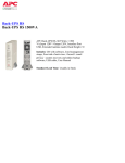
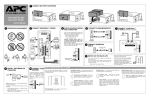
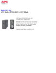
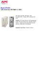
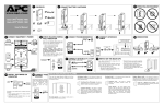
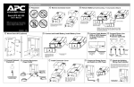
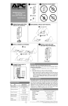
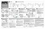
®
1 CONNECT BATTERY CARTRIDGE
w w w.apc.com
Back-UPS® RS 800
User’s Manual
2 OPERATING ENVIRONMENT
3 CONNECT EQUIPMENT / POWER
4 CONNECT PHONE/MODEM/FAX
6 CONNECT 10/100 Base-T or VOIP
Phone Jack
Data Port
10/100 Base-T / VOIP
Circuit Breaker
Push to Reset
TVSS GND
0 - 40oC (32 - 104oF)
TVSS GND
Modem/Fax/Phone
Wall
Outlet
CABLE
Monitor
10/100 Base-T / VOIP
Wall
Outlet
Modem/
To Computer USB
Port
USB
RJ-45
Data Port
✘
5 CONNECT INTERFACE
Data Port
✔
Computer
Network Port
Computer
BATTERY BACKUP
SURGE ONLY
✔
220-240V~, 3A, 50-60Hz, 540W
Network Jack
Computer
Modem Port
Printer or Scanner
FAX
Modem/Fax/Phone
Wall
Outlet
Computer
30 cm
Input: 220-240V~, 7A, 50-60Hz 220-240V~, 3.5A, 50-60Hz, 540W
External Disk or
CD / DVD Drive
Your Computer
Power Cord
8 INSTALL SOFTWARE ON
COMPUTER
Follow the
on-screen
instructions.
To 220-240 VAC, 50-60 Hz
GROUND
The Back-UPS features a transient
voltage surge-suppression (TVSS)
screw for connecting the ground
lead
on
additional
surge
suppression devices such as
network and data line surge
protectors.
1. On the computer desktop of the display, doubleclick on My Computer.
2. Double-click on the CD-ROM drive icon and
follow the on-screen instructions.
Wall
Outlet
TVSS GND
Modem/Fax/Phone
If Autoplay is not enabled on the computer, proceed
as follows:
Note: Allow the Back-UPS to charge for a full eight (8)
hours prior to use.
Press the front panel Power ON/OFF switch and observe
that the following events occur after pressing and
releasing the switch:
• The green On Line indicator flashes.
• The yellow On Battery indicator lights while
a Self-Test is being performed.
• When Self-Test has successfully completed,
only the green On Line indicator will be lit.
• If the internal battery cartridge is not
connected (see Step 1 above), the green On
Line indicator and red Replace Battery
indicators will light. The Back-UPS will also
emit a chirping sound.
STATUS INDICATORS AND ALARMS
9 CONNECT TVSS
There are four status indicators (lights) on the front
panel of the Back-UPS (On Line, On Battery, Overload,
and Replace Battery).
Overload (red) - is lit whenever power demand has
exceeded the capacity of the Back-UPS.
Continuous Tone - this alarm is sounded
whenever the Battery Backup outlets are
overloaded.
On Line
Overload
From Data Line
TVSS
On Battery (yellow) - is lit whenever the battery of
the Back-UPS is powering equipment connected to the
Battery Backup Outlets.
Four Beeps Every 30 Seconds - this alarm is
sounded whenever the Back-UPS is running On
Battery. Consider saving work in progress.
On Battery
NOTE: Macintosh Users - for full USB performance,
use OS 9.22 or higher.
7 SWITCH ON THE BACK-UPS
Replace Battery
On Line (green) - is lit whenever utility power is
powering the Battery Backup outlets.
Continuous Beeping - this alarm is sounded
whenever a low battery condition is reached.
Battery run-time is very low. Promptly save any
work in progress and exit all open applications.
Shutdown the operating system, computer and
the Back-UPS.
Circuit Breaker - the circuit breaker button
located on the rear panel of the Back-UPS will
stick out if an overload condition forces the BackUPS to disconnect itself from utility power. If the
button sticks out, disconnect non-essential
equipment. Reset the circuit breaker by pushing
the button inward.
Replace Battery (red) - is lit whenever the battery is
near the end of its useful life, or if the battery is not connected (see above). A battery that is near the end of its useful life has insufficient run-time and should be replaced.
Chirps for 1 Minute Every 5 Hours - this
alarm is sounded whenever the battery has failed
the automatic diagnostic test.
SPECIFICATIONS
TROUBLESHOOTING
SERVICE
If the Back-UPS arrived damaged, notify the carrier.
Problem
Back-UPS will not switch on.
Possible Cause
Item
Corrective Action
Back-UPS not connected to AC power source.
Ensure the Back-UPS is securely connected to an AC outlet.
Back-UPS circuit breaker “tripped”.
Disconnect non-essential equipment from the Back-UPS. Reset
(push in) the rear panel circuit breaker. Switch on the Back-UPS
and plug in devices one at a time. If the circuit breaker trips
again, disconnect the device that caused the breaker to trip.
Utility input voltage quality is out of range.
Consider adjusting the transfer voltage and sensitivity. See
Transfer Voltage and Sensitivity Adjustment.
Specification
On-line Input Voltage Range
(default settings)
175 - 295 Vac
Automatic Voltage Regulation (AVR)
+12%
On-line Frequency Range
47 - 63 Hz (autosensing)
On-battery Waveshape
Stepped Sine Wave
Maximum Load
800 VA - 540 W
Internal battery cartridge is not connected.
Connect battery cartridge (see Connect Battery Cartridge).
Typical Recharge Time
8 Hours
Back-UPS does not power
essential equipment during an
outage.
Equipment plugged into a Surge Only outlet.
Unplug device from 'Surge Only' outlet and move to a 'Battery
Backup' outlet.
Operating Temperature
o
Back-UPS operates on battery
although utility power exists.
Back-UPS circuit breaker “tripped”.
Disconnect non-essential equipment from the Back-UPS. Reset
(push in) the rear panel circuit breaker. Switch the Back-UPS on
and plug equipment in one-at-a-time. If the circuit breaker trips
again, disconnect the device that caused the breaker to trip.
Storage Temperature
0 to 40oC
(32o to 104oF)
-5o to 45oC
(23o to 113oF)
Operating / Storage Relative Humidity
0 to 95% non-condensing
Utility input voltage quality is out of range.
Consider adjusting the transfer voltage and sensitivity. See
Transfer Voltage and Sensitivity Adjustment.
Size (H x W x D)
Back-UPS is heavily loaded.
Unplug non-essential equipment (printers, scanners, etc) from
the Battery Backup outlets and plug into 'Surge Only' outlets.
Weight
9.3 kg (20.5 lbs)
Back-UPS battery cartridge is discharged due to
recent power outage and has not had time to
recharge.
Charge the battery cartridge for 8 hours. Back-UPS runtime is
reduced until the battery cartridge is fully charged.
Shipping Weight
9.9 kg (22 lbs)
EMI Classification
Battery has reached the end of its life.
Replace battery cartridge (see Order Replacement Battery
Cartridge).
Red Replace Battery indicator is
flashing. Green On Line indicator
is on.
Internal battery cartridge is not connected.
Connect battery cartridge (see Connect Battery Cartridge).
Red Replace Battery indicator is
on.
Battery has reached the end of its life.
Replace the battery cartridge (see Order Replacement Battery
Cartridge).
Red Overload indicator is on or
flashing.
Connected equipment is drawing more power than
the Back-UPS can provide.
Move one or more equipment power plugs from Battery Backup
outlets to Surge Only outlets.
Green On Line indicator is on and
all other front panel indicators are
flashing.
Internal UPS fault.
Contact APC Technical Support (see Contact Information).
Back-UPS does not provide
expected backup time.
ORDER REPLACEMENT BATTERY CARTRIDGE
The battery cartridge typically lasts 3-6 years, shorter if subjected to frequent outages or elevated temperatures. Order part number RBC32.
Please recycle spent battery cartridges.
REPLACE BATTERY CARTRIDGE
1
2
23 x 10 x 32 cm
(9 x 4 x 12.75 inch)
EN 50091-1, EN 60950, EN 50091-2, EN
61000-3-2, EN 6100-3-3,
EN 55022 Class B
On Battery Run-Time
See http://www.apc.com/product
TRANSFER VOLTAGE AND SENSITIVITY
ADJUSTMENT
4
1.
2.
3.
4.
Consult the Troubleshooting section to eliminate common problems.
If the problem persists, go to http://www.apc.com/support/.
If the problem still persists, contact APC Technical Support.
Have the Back-UPS model number, serial number and date of purchase
available. Be prepared to troubleshoot the problem with an APC Technical
Support representative. If this is not successful, APC will issue a Return
Merchandise Authorization (RMA) number and a shipping address.
LIMITED WARRANTY
The standard warranty is two (2) years from the date of purchase. APC’s standard
procedure is to replace the original unit with a factory reconditioned unit.
Customers who must have the original unit back due to the assignment of asset
tags and set depreciation schedules must declare such a need at first contact with
an APC Technical Support representative. APC will ship the replacement unit
once the defective unit has been received by the repair department, or cross-ship
upon the receipt of a valid credit card number. The customer pays for shipping the
unit to APC. APC pays ground freight transportation costs to ship the replacement
unit to the customer.
CONTACT INFORMATION
Technical Support
Internet
USA / Canada
Mexico
Brazil
Worldwide
http://www.apc.com/support
http://www.apc.com
1.800.800.4272
292.0253 / 292.0255
0800.12.72.1
+1.401.789.5735
In situations where the Back-UPS or connected equipment appears too sensitive
to input voltage, it may be necessary to adjust the transfer voltage. This is a
simple task requiring use of the front panel pushbutton. To adjust the transfer
voltage, proceed as follows:
1. Plug the Back-UPS into the utility power source. The Back-UPS will be in a
Standby Mode (no indicators lit).
2. Press the front panel pushbutton fully inward for 10 seconds. All indicators
on the Back-UPS will flash to acknowledge going into Programming Mode.
3. The Back-UPS will then indicate its current Sensitivity Setting, as shown in
the following table.
Indicators
Flashing
Sensitivity
Setting
1
(yellow)
Low
Input Voltage
Range
(for utility
operation)
3
(yellow,
red, and
red)
High
Use When
156 - 300 Vac Input voltage is extremely low or
high. Not recommended for
computer loads.
2
Medium
176 - 288 Vac
(yellow, (factory default)
and red)
3
If the Back-UPS requires service, do not return it to the dealer. The following
steps should be taken:
Back-UPS frequently goes On
Battery.
176 - 278 Vac Connected equipment is sensitive
to voltage fluctuations
(recommended).
4. To select the Low Sensitivity setting, press the pushbutton until the yellow
indicator is flashing.
5. To select the Medium Sensitivity setting, press the pushbutton until the
yellow and red indicators (second and third from the top) are flashing.
6. To select the High Sensitivity setting, press the pushbutton until yellow and
both red indicators (bottom three) are flashing.
7. To exit without changing the Sensitivity Setting, press the pushbutton until
the green indicator is flashing.
8. Once in Programming Mode, if the pushbutton is not pressed within 5
seconds, the Back-UPS will exit Programming Mode; all indicators will
extinguish.
990-1435-001 1/04 Copyright © 2004 American Power Conversion All rights reserved.
APC and Back-UPS are registered trademarks of American Power Conversion.
All other trademarks are the property of their respective owners.