1
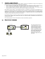
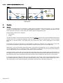
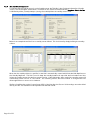
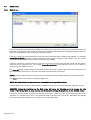
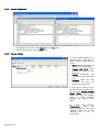
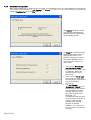
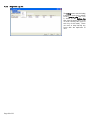
User Manual EXgarde ENTERPRISE Disaster Recovery Access Management Software To Register your Product, Visit http://www.tdsi-product-registration.co.uk UM0034 Issue 1 12/2008 HELP US TO HELP YOU Every effort has been made to provide you with error free information. However if you do find any inaccuracies or feel that some additional information would be useful in this manual then we would like to hear from you. Please copy and complete the form below and fax it back to us on +44 (0)1202 724975 marked for the attention of ‘TDSi Marketing Department’ or post it to: TDSi Unit 10 Concept Park Innovation Close Poole Dorset BH12 4QT, UK Alternatively e-mail it to: [email protected] User Manual Improvement Form Manual № UM0034 Issue 1 About You Name Company Main Company Activity Address Telephone Number E-mail Address Your Comments Please provide full description of the error or your suggested improvement, including page and section numbers. Thank you, TDSi Marketing Team Log ID Page 3 of 32 DL NOTICES Manufacturers Details This product is designed and supplied by: Time and Data Systems International Ltd (TDSi) Unit 10 Concept Park Innovation Close Poole Dorset BH12 4QT, UK Telephone: +44 (0)1202 723 535 Fax: +44 (0)1202 724 975 E-mail: [email protected] Web: http://www.tdsi.co.uk Copyright Notice Copyright © 2008 Time and Data Systems International Ltd (TDSi). This document or any software supplied with it may not be used for any purpose other than that for which it is supplied nor shall any part of it be reproduced without the prior written consent of TDSi. TDSi Policy Time and Data Systems International Ltd operate a policy of continuous improvement and reserves the right to change specifications, colours or prices of any of its products without prior notice. Page 4 of 32 Introduction to EXgarde Enterprise................................................................................................................................................................6 1.1 Modes of Operation - Hot Standby ..........................................................................................................................................................6 1.2 Modes of Operation - Resilient Duplication..........................................................................................................................................7 1.3 Modes of Operation - Schematic...............................................................................................................................................................7 1.3.1 Normal Operation......................................................................................................................................................................................7 1.3.2 Link Broken Between Sites...................................................................................................................................................................7 1.3.3 Link Re-Established Between Sites...................................................................................................................................................8 2 Overview.........................................................................................................................................................................................................................8 2.1 General................................................................................................................................................................................................................8 2.2 Data Organisation...........................................................................................................................................................................................9 2.3 Replication Link Topology........................................................................................................................................................................ 10 2.4 Replicator........................................................................................................................................................................................................ 11 2.5 Off-Line Re-Synchronisation................................................................................................................................................................... 12 2.6 Hot Standby Server .................................................................................................................................................................................... 12 2.7 Technical Changes ...................................................................................................................................................................................... 13 3 Installing EXgarde Enterprise .............................................................................................................................................................................. 14 3.1 Installation ..................................................................................................................................................................................................... 14 3.2 Before starting ............................................................................................................................................................................................. 15 3.2.1 File win32client...................................................................................................................................................................................... 16 3.2.2 File win32client.ws32.......................................................................................................................................................................... 16 3.2.3 Files dbnt25sv For Each of the Server PCs ................................................................................................................................. 16 3.2.4 Example ..................................................................................................................................................................................................... 17 4 System Configuration ............................................................................................................................................................................................. 18 4.1 EXgarde License Server (EXls) ............................................................................................................................................................... 18 4.1.1 General ....................................................................................................................................................................................................... 18 4.1.2 Site Configuration.................................................................................................................................................................................. 19 4.1.3 Inter-Site Link Configuration – Creating the Replication Links............................................................................................. 20 4.1.4 Hot Standby Configuration ................................................................................................................................................................ 21 4.2 EXgarde Enterprise EXplorer .................................................................................................................................................................. 22 4.2.1 Login ........................................................................................................................................................................................................... 22 4.2.2 The EXgarde Enterprise User Interface ........................................................................................................................................ 23 4.2.3 Alarms......................................................................................................................................................................................................... 24 4.2.4 Photographs and Background Images ........................................................................................................................................... 24 4.3 EXReplicator .................................................................................................................................................................................................. 25 4.3.1 Main Screen.............................................................................................................................................................................................. 25 4.3.2 Process Diagnostics .............................................................................................................................................................................. 26 4.3.3 Process Actions ...................................................................................................................................................................................... 26 4.3.4 Replication Configuration ................................................................................................................................................................... 27 4.3.5 Diagnostic Log File ................................................................................................................................................................................ 29 4.4 EXBackup........................................................................................................................................................................................................ 30 4.4.1 Site Conversion....................................................................................................................................................................................... 30 4.4.2 Database Merge Tool............................................................................................................................................................................ 30 4.4.3 The Merge Process................................................................................................................................................................................ 31 4.4.4 Additional Information. ........................................................................................................................................................................ 31 4.4.5 Log File....................................................................................................................................................................................................... 31 Glossary of Terms.............................................................................................................................................................................................................. 32 1 Page 5 of 32 1 Introduction to EXgarde Enterprise EXgarde Enterprise is an expansion of eXguard PRO to support the requirements of large scale customers by incorporating two new features giving the application the ability to: attach a mirrored hot-standby server to an EXgarde system, this containing an instance of eXguard Licence Server as well as the database giving the EXgarde installation full Disaster Recovery facilities and; connect multiple EXgarde installations together allowing them to share all data. This provides central administration and control but also retains the resilience of separate local installations. The backbone of the system is a client application known as a Replicator. The purpose of the Replicator is to connect to one EXgarde system, process operator actions and events, to identify changes to the system, and then implement the same changes on a remote EXgarde system. The advantage that this has over simple database duplication is that since this is a transaction based system it is highly less likely that any system table based corruption would be duplicated between the two systems. The Replicator includes a secondary system in that if the connection to the remote site is lost, the Replicator is aware of what changes have occurred and upon the connection being re-established the remote site is synchronised to match. The following diagrams show how the Replicator achieves the different operations. 1.1 Modes of Operation - Hot Standby EXgarde Main Replicator Client PCs Page 6 of 32 EXgarde Standby Replicator The diagram opposite shows a simple implementation of the Replicator to keep the Standby System instep with the Main System. The EXgarde Licence Servers communicate with each other so if the main server fails the standby system becomes the live server and all client applications change over to use this server. 1.2 Modes of Operation - Resilient Duplication EXgarde System 2 EXgarde System 1 Replicator Replicator The Replicators are configured to have two-way data transfer and then any changes on either system are reflected on the other. This will allow two EXgarde systems with their own client machines connected to each one, to behave as a single EXgarde system with all clients seeing all data and events. This configuration allows for very flexible redundancy in that if either server fails then the clients belonging to that server can be reconfigured to connect to the other running server. If a database is damaged a duplicate of the data is stored on the other server. If the two systems are separated by a WAN then if the WAN is broken the local clients can still communicate with their local server. 1.3 Modes of Operation - Schematic The following diagrams show the interconnection between the components of EXgarde for two sites during different modes of operation. 1.3.1 Normal Operation Site 1 Site 2 EXplorer eXcomms IP/485 Adaptor eXcomms Database & EXls Replicator Replicator Database & EXls EXplorer ACU ACU Configuration, Tenant & Event data 1.3.2 Link Broken Between Sites Site 1 Site 2 EXplorer eXcomms IP/485 Adaptor eXcomms Database & EXls Replicator Replicator Database & EXls EXplorer ACU Page 7 of 32 ACU 1.3.3 Link Re-Established Between Sites Site 1 Site 2 EXplorer eXcomms IP/485 Adaptor eXcomms Database & EXls Replicator Replicator Database & EXls EXplorer ACU ACU Configuration, Tenant and Event Data Catch-up 2 Overview 2.1 General To represent multiple EXgarde installations, a single EXgarde installation will now be known as a Site, with the System as a whole becomes a set of inter-linked EXgarde installations. To allow continuing operation of a Site even if the inter-connection is down each Site contains copies of all appropriate data. EXgarde objects fall into two categories Site Specific Global. Site Specific objects are those that where listed under the Building branch in the standard EXgarde Explorer and includes items such as Equipment (Computers, ACUs etc), Areas, Schedules and Database Users. These are related physically to a specific location. The Global data is the Tenant data, which could be applicable to one or many Sites. Each Site has a unique Site ID, this has a value between 1 to 64 and is defined in the configuration of each Site. This provides information on which site the information created the data, even if it’s for another site. Replication is a transaction based system that passes a description of the operation, such as creating a key holder and any appropriate data to a connected system. The destination system then uses the standard functionality to carry out the changes to the local database. See Section 2.4 for more details. Events and Alarms can be visible on all sites but due to the interactive nature of Alarms they must be ‘Owned’ by a Site. Operators attached to any other site will see the Alarm duplicated by replication but before they can process the alarm they must request ownership of the alarm from the current owning site. See section 4.2.3 for details In Evaluation mode two replication links and two workstations are included. This allows demonstration of twoway resilient replication (2 links) or a full hot standby system (1 link, 2 workstations) with standby server and a client workstation to show EXgarde EXplorer and EXgarde communications (EXcomms) changeover. Page 8 of 32 2.2 Data Organisation Site 1 is defined as the ‘Master’ and contains a list of the system Sites, their names and IP address as well as definitions of their inter-connections or ‘Links’. From this information the system knows the number of sites and adds them to the EXgarde EXplorer Outline. The Site information can only be entered on the ‘Master’ site’s EXgarde Licence Server (EXls) but to allow for configuration of additional sites, without the need for the Replication system to be running, the information can be exported to a file and then manually transferred to the other sites and imported into their EXls. The Building branch of the outline view as found in the traditional EXgarde PRO interface becomes a Site. Multiple sites can exist within the system. Each Site contains Schedules, Database Users, Areas, Equipment and Alarm Zones. The Tenants appear as they do in the usual EXgarde PRO interface but the use of these depends on how you wish to organise the data. As the Tenants have no direct relationship to a physical site, a single Tenant could be used across all the sites or have individual Tenants for each Site. This may be desirable to keep key holders and access groups separate for each site and to ease key holder management. To limit which sites are visible to an Operator, Sites have a ‘Sharing’ tab, (in a similar fashion to that found in the Areas section of the software), which allows you to specify which Tenants can see the site. Although an EXgarde EXplorer connected to one Site can create objects on other Sites, Communications, PCs, ACUs, CCTV Controllers and Database Users, creation and Intruder configuration can only be achieved from an EXgarde EXplorer physically connected to that site. This is done to retain licensing for an individual site. Page 9 of 32 2.3 Replication Link Topology To provide the ability for sites to be used as hot standby sites or as duplicates and to support different topologies, the type of interconnection between sites is configurable. There are three types of links: Replication Links Distribution Links and Mirror Links. Replication Links Replication links pass changes from a source site to destination sites. If the data is to be replicated across multiple sites then the site is responsible for updating all of the other sites with changes carried out by the locally connected workstations. In this case the system will consist of multiple links. For n sites the number of links required can be calculated as n*(n-1). For example if there are 4 sites then the number of links will be: 4*(4-1) =4*3 =12 links. Distribution Links Distribution links pass changes from a source site to a single destination. The destination then adds the transaction to its own Transaction Table and then passes it out to all its destinations except the originator of the transaction. In this system the number of links required for the system consisting of n sites can be calculated as (n-1)*2. For example if there are 4 sites then the number of links will be (4-1)*2 =3*2 =6 links. Mirror Link Page 10 of 32 A Mirror link passes all data to a single destination site including all of the site configuration data (normally transferred by replication). This results in the destination site being an exact duplicate of the source site. This is configuration can be utilised to create a Hot Standby. 2.4 Replicator Replication is a real-time data replication system that uses a transaction based methodology, where instead of just passing the resultant database changes it sends a description of the action taken on the Source Site that is then processed through the standard EXgarde functionality at the Destination Site thus creating the same database changes. In addition the appropriate local actions are passed such that clients and ACUs attached to the destination Site are affected in the appropriate way. The source of Transactions are the same as system events such as operator actions or ACU events. A Transaction Summary is placed in a Transaction Table, which acts as a buffer for transmission of the messages to the appropriate sites. The interconnection between Sites is carried out by an application called the Replicator, which performs two types of process: Replication Server Replication Client. A Replicator Client at the Source Site is connected to a Replicator Server at the destination site via a TCP/IP socket and passes data as a Transaction Message which contains all of the data for all the related objects in the that transaction. The following shows the process from a client changing data on one Site to be pass via the Replicators to a second Site The Replication Transmitter manages a set of Replication Client windows, one for each Destination Site. The Replication Receiver manages a set of Replication Server windows; this may be one for all sites or one for each Source Site that is required to connect to it. The system has been designed such that the Transmitter and Receiver communicate with the Client and Server windows, respectively in a standard way and the Client and Server windows communicate independently, for example the initial type will use a TDSi defined Transaction message passed via a TCP/IP socket. The Replicator application will automatically connect to the EXgarde database and start processing when started (in a similar way to the EXgarde Communications application, EXcomms). To exit or to change configuration the application will need to be logged into, similar to EXgarde EXporter. Page 11 of 32 2.5 Off-Line Re-Synchronisation Replication re-synchronisation is a mode where two sites re-connect after a period of operating off-line. Whilst in this mode, any transactions which have been logged off-line will be transmitted and executed in batches. If the period of disconnection is considerable, it may be quicker to rebuild one of the databases using the EXgarde backup tool. When a link between two sites is broken, the client changes from real-time replication to the off-line process. The client will start to export the transactions into Transaction Export Files *.TEF. These will be labelled SS-DD-NNN.TEF, where SS is the Source ID (1 to 64), DD is the Destination ID (1 to 64), NNN is a sequential number between 000 to 999. As transactions are created, the replication application exports these transactions into a TEF file. If the TEF file is greater than 250 Kbytes it will start a new file with the next sequence number until it reaches 999. This method will help keep the transaction table clean to provide the best performance on delivery. When the two sites re-connect together, they will go into a re-synchronisation mode and send each TEF file to the destination server, which will import automatically the transactions. When a file has been transferred successfully it will be renamed as SS-DD-NNN-YYYYMMDDHHMM.TMP (where YYYY is the year, MM is the month, DD is the day, HH is the hour and MM the month). If the process fails, the file will be renamed to an ITF file (Import Transaction File). This will allow you to manually import this file. The TMP files will be automatically deleted after a day or two. It is possible to manually apply the off-line transactions by taking one or more TEF files to the destination site and import the transactions manually. For example, file 03-01-000.TEF is a list of transactions for site 01 from site 03. Copy this file from Site 03 to Site 01 and then delete it from Site 03. Note if more than 1 file exists it is recommended that all files are processed together. This will then allow for Site 03 to start again with the sequence of 000. With the file on Site 01, right click on a server from the list of servers and clients in the application window and select the Show option. This will display the server window. From its menu, select File/Import. This will allow you to browse to the TEF file, select it and import the data. Repeat this for all files to be imported. The manual merge is recommended when you are going to rebuild Site 03 from Site 01. 2.6 Hot Standby Server Two sites linked with a Mirror Link result in a Main and Standby site, which are exact duplicates of each other. The active site is known as the Live site. As part of the Mirror Link the licence information is also copied across allowing the Standby site to run for 15 days in place of the Live server. The Replicator application on the Standby server will start and like all EXgarde applications communicate with the licence server. Once this connection is established it will notify the licence server to run in ‘Standby Mode’ (which will be the default mode for licence server running on a standby machine). When running in this mode no other applications will be able to connect to it. The Replicator application will then create a listening link for the main server to connect. If a request to connect has not be received from the Main server within a specified time (45 seconds by default) the Replicator then assumes that the Standby server is to become the Live server and informs the licence server to switch to ‘Acting Sever Mode’. The licence server will then allow other applications to connect. The Replicator application will create any required replication or distribution links and behave the same as a Main server. When the Standby server is running as the Live server, the original server database will be considered out-of-date. Since this would normally occur when the Main server has failed and the time to recovery could be considerable, the process to return the Main server is to take a copy of the final database on the Standby server. It is possible to force the switchover to the standby server and back again from the Main server. This is carried out as follows: Logging-in to the Replicator application on the Main server right-click on the link between the Main and Standby server selecting Switch Standby Server Mode menu option. Page 12 of 32 To force client applications to change from the Main to Standby server either: close the Main EXls or use the Suspend function to disconnect the clients and to cause then to restart. When client workstations attempt to attach to the Main server and fail, they then try to connect to the Standby server and then back again until they successful connect. The server the client is attempting to attach to is indicated in the TCM connection dialog by the IP address of the server it is attempting to connect to. 2.7 Technical Changes Note: EXgarde Enterprise is an based on eXguard PRO 2.2.0 and it is not possible to upgrade later versions of EXgarde PRO to EXgarde Enterprise. The database file UG2000.dbs has been replaced and each site now has its own data file XGARDExx.dbs where xx is a two digit number representing the site id, i.e. site 01 (which is the Master site) is XGARDE01.dbs. If the site is a hot standby then the database is EDRAGxx.dbs. The Servernames are also unique with ServerX for main sites and MirrorXX for standby sites. Replicators connect via TCP/IP sockets and therefore DCOM between sites is not normally necessary. However to be able to log on to a client PC from one site to the server of another does require a DCOM connection as normal. Although the log-in screen of the EXgarde EXplorer allows the selecting of different sites, the TCMClient is used by all EXgarde client applications running on that workstation. Therefore all applications on the workstation will be connected to the selected site so if it is necessary to change the site it is recommended that the workstation should be used for EXgarde EXplorer only and this is never done on the server. For sites with a Main and Standby server, client applications such as EXgarde EXplorer and EXcomms must run on client machines and NOT on either the Main or Standby servers, otherwise they will not be able to switch automatically between them. EXgarde Enterprise has the ability of supporting up to 64 sites and to connect clients for any of these sites the Database Engine installed now supports up to 75 workstations to be connected concurrently. The number of actually licensed workstations is still controlled by the EXgarde License Server (EXls). Page 13 of 32 3 Installing EXgarde Enterprise 3.1 Installation Additional to the normal installation process you need to enter the site number (1-64) for the site being installed. For the Master site the site number is 1. For a Standby site this is given the same site number as the main site. Click on the Next button to begin the installation process. As well as the standard ‘Database Server’ option for configuring the installation as the Server PC, a second option of ‘Standby Database Server’ will configure the Server as a standby server. If selected, his option automatically selects the ‘Database Server’ option so the standard server applications are installed. Once the appropriate options have been selected, click on the Next button to continue the installation process. Page 14 of 32 For a server installation the desktop and start up screens have an option for the Replicator. Similar to the EXgarde communications application, it is recommended that the EXgarde Replicator option be select for the start up group. Click on the Next button when done. 3.2 Before starting If you want to upgrade an existing eXguard Pro database, setting the Site ID to a value of 64 before starting the EXgarde License Server (EXls) will make the necessary updates to the database schema and convert the database to a sited database. To do this: Open the System Registry by selecting Run from the Start button. In the Open field type “regedit” and click on OK. Browse to the HKEY_LOCAL_MACHINE\SOFTWARE\TDSI\Global and select the key ‘Home Site’ wher the ID of the site is specified. Change the value of this parameter to 64. Remember that the displayed value is normally shown in base 16 or Hexidecmial. Once the database has been updated it is necessary to shut down EXgarde License Server (EXls) and the database directory and file renamed from UG2000 to the appropriate name (see section 2.7 for naming the convention of the EXgarde Enterprise databases.). The DBServer key should have the actual IP address of the server and NOT 127.0.0.1. This is true for the Server PC also. It is recommended not to use EXgardeConfig to accomplish this as this will also set the server address in SQL.INI. This NEEDS to be 127.0.0.1 or localhost to start the database engine automatically. Page 15 of 32 If you wish to connect a client from one system to another then it is necessary to modify 3 files. A modification to the file [win32client] is required whereby it is necessary to include a line for each database. The file [win32client.ws32] needs an entry for each server PC. Finally on each server the file [dbnt25sv] needs the Servername to be modified and needs to be unique to that site with ServerX for main sites and MirrorXX for standby sites. Details of the file contents and modifications can be found in the sections. 3.2.1 File win32client [win32client] dbname=XGARDE01,sqlws32 dbname=XGARDE02,sqlws32 dbname=XGARDE03,sqlws32 3.2.2 File win32client.ws32 [win32client.ws32] serverpath=Server1,10.0.0.1/ XGARDE01 serverpath=Server2,10.0.0.2/ XGARDE02 serverpath=Server3,10.0.0.3/ XGARDE03 3.2.3 Files dbnt25sv For Each of the Server PCs On Site 1 server: [dbnt25sv] dbname= XGARDE01,sqlws32 servername=Server1,sqlws32 On Site 2 server: [dbnt25sv] dbname= XGARDE02,sqlws32 servername=Server2,sqlws32 On Site 3 server: [dbnt25sv] dbname= XGARDE03,sqlws32 servername=Server3,sqlws32 Page 16 of 32 3.2.4 Example For an installation where Site 1 has a Standby server On the Client PC [win32client] dbname=XGARDE01,sqlws32 dbname=EDRAGX01,sqlws32 [win32client.dll] comdll=sqlws32 [win32client.ws32] serverpath=Server1,10.0.0.1/XGARDE01 serverpath=Mirror01,10.0.0.101/EDRAGX01 On the Main Server PC [dbnt25sv] servername=Server1,sqlws32 DBNAME=XGARDE01,sqlws32 On Standby Server [dbnt25sv] servername=Mirror01,sqlws32 DBNAME=EDRAGX01,sqlws32 Page 17 of 32 4 System Configuration 4.1 EXgarde License Server (EXls) 4.1.1 General EXgarde License Server (EXls) needs to be running to be able to close or save the settings on the Site tabs. This is a normal EXgarde operation for the local site. Note: after logging-in the connection will timeout after 5 minutes so it may be necessary to log back in before saving any changed data. A component of the supplied licence is the number of supported links. A link is a one-way communications path so for replication in both directions between two sites two links are required. Two new tabs are added to EXgarde License Server (EXls) The tab Sites contains the parameters for the 64 available sites The tab Links define the inter-site connections. The entering and editing of the information contained within the Sites and Links tabs can only be accomplished on the EXgarde License Server (EXls) on the Master Site (Main server Site 01). The same data is available of all other Satellite EXls but only in a read-only format. Page 18 of 32 4.1.2 Site Configuration On the Site tab the table contains entries for all of the individual site IDs. The table is only editable on the Master site on which there are two buttons available - Export and Save. On the Master site Name, Long Name, Comment, Server Address, Standby Address and Alarm Owning Site are standard text entry fields. Figure 1 - Information on the Site Tab as Displayed on the Master Site On all other sites the table is non-editable and the buttons available are Import and Save. The Mode field is a dropdown list containing the following options Unused - clears the whole row and also stops the site from being displayed in the outline in each instance of EXgarde EXplorer. Enabled and Disabled - shows the Site in EXplorer but the replication links are disabled. Figure 2 - Information on the Site Tab as Displayed on Satellite Sites The Sever and Standby Address field applies the traditional IP address formatting upon exiting the form and if an invalid entry has been made notified of this. The Server address is the IP address of the PC on which it is running to act as the Main server for this site while the Standby Server is the Mirror server to act as a hot standby. The Alarm Owning Site is a drop down containing all of the sites and specifies when an alarmed event occurs and which site has initial control. By default this is set to Site 01 (the Master) which is usual for a centrally administered system but if each site is responsible for its own hardware then having each site set to itself (i.e. control for it’s own alarmed events) then this may be more appropriate. Any changes made in the form enables the Save button which must be clicked on to commit the changes made to the database. If the tab is changed while there are un-saved changes then a dialogue box is displayed asking if the changes should be discarded. If No is selected then the focus remains on the Site tab. The table is loaded each time the tab is selected. The Export button saves the site and link information to a file - SITE.UIF in the installation folder of EXgarde. The Import button allows the an exported SITE.UIF file to be selected and imported, loading it’s contents into the local database. Page 19 of 32 4.1.3 Inter-Site Link Configuration – Creating the Replication Links The table as shown on the Links tab is only editable on the EXgarde License Server of the Master site. In addition all links are shown in the Links table for the Master site but on all other sites, only the links to and from that site are shown. To create a new link: click in the Add button. This will create a blank row in the table. Select this blank row and type the required data. Should you attempt to create more links than the license allows for then an error message is displayed informing you of this is displayed Select the Source and Destination of of the link. The Source and Destination drop down boxes contain only the configured sites. When creating a new link the Source and Destination will contain all of the available sites. However as soon as an available site has been selected it will be removed from the other list. This prevents the same site being specified as both the Source and Destination for the link. If the source is made available again, for example if it is changed then it is added back into the destination and the new source removed etc. The Port is the IP port to be used, the default port is 20002. It is fully user configurable can be different for each link if required but it is advised to use the default setting. If multiple sites use the same port number for a destination then a single server process is created on the destination site, if different ports are specified for the same destination multiple server process are created. Note: The Ports cannot be the same for different Link Types for the same destination site, i.e. for a destination if some links are going to be Replication links and others Distribution, then these two types must be on different ports. The Type field is a drop down list containing 3 options: Replication - This setting are for links that simply transfer transactions from a source to a destination site Distribution – this setting is for a link that transfers transactions to the specified destination but as well as performing the transaction to its own system it then forwards the transaction to its other destinations. Mirror is only display for automatically created Mirror links and is not editable. The State field is a drop down list containing Enabled, Disabled Unused. This option clears the whole row. Changes in any of the fields enable the Save button which must be clicked on to commit the changes made to the database. If the tab is changed while there are un-saved changes then a dialogue box is displayed asking if the changes should be discarded. If No is selected then the focus remains on the Site tab. Any changes will create TCM messages to update the local replicators and also to be transmitted to other sites. Page 20 of 32 4.1.4 Hot Standby Configuration To indicate that the License server is on the Standby server the Title Bar is the Site Name followed by (Standby Server) – see the examples shown below. In addition on the Status Information tab the Database Status On-line is followed by either (Standby Mode) or (Acting Server Mode) when the standby server is live. Below is an example where Site 3 has a standby server defined. This is achieved by simply defining the standby address. When the site standby address is specified, a new link is automatically created which links the Main Replicator to the Standby Replicator. This link is used to keep the standby database in-step with the live database and also inform the standby server that the live system is active. If this link breaks, after a period the standby server will automatically switch and act as a live server. This switching informs the Licence Server to change modes and allows applications to connect to its database. Similar to Satellite sites, on the License Server (EXls) of the Standby the Sites and Links settings cannot be edited directly and the SITE.ULD file must be imported from the Main server. Page 21 of 32 4.2 EXgarde Enterprise EXplorer 4.2.1 Login The login screen now allows the selection of the site to connect to using the Site filed. When starting for the first time, the Site field only contains the Home Site so that it can connect to the database and fetch the list of all of the sites and populate its local copy in the registry. For subsequent login attempts the Site list contains all of the site numbers and the Names of the sites. Any changes will not be shown until the local EXgarde License Server (EXls) has been updated with changes from the Master site and the Explorer has connected at least once. Page 22 of 32 4.2.2 The EXgarde Enterprise User Interface The following figure shows a typical main screen of EXgarde Enterprise application. 6 7 1 3 4 5 2 1 – Toolbar 2 – Shortcut Bar 3 – Outline View 4 – Working Area 5 – Help Area 6 – Title Bar 7 – Menu Bar If the EXgarde EXplorer is connected to the Standby server then the Title Bar reflects this by having (Standby) after the site name. The Outline View is separated into two sections, the Sites with their hardware and the Tenants. Access Controlled Sites is a collection of multiple Buildings (as can be found in the traditional version of EXgarde PRO) which are now referred to as Sites. Each site has its own Equipment, Areas etc. Note: there is a Public and Master Alarm Zone for each Site. Initially the access group Everyone is only applied to area Public 1 (Public for Site 1). Access to Area Public for Sites other than Site 1 needs to be done by adding it to an appropriate access group manually or by applying the Access Group Everyone to the relevant Public areas. The Properties of a Site has a Sharing tab, in a similar way to that found in the Areas section of the application, which defines which Tenants can view a particular site. This allows the easy creation of ‘Site only Tenants’ which only see their own local Site as only the Site that the Operator’s Tenant is ‘Shared’ with will be displayed in the outline. The creation of licensed objects, such as Computers, ACUs (i.e. Doors), CCTV Controllers and configuring Intruder integration, can only be done by the EXgarde EXplorers directly connected to that Site. This allows the EXplorer to know the licensed options for that Site and thus only create objects allowed for. Page 23 of 32 4.2.3 Alarms Events and Alarms can be made visible on all sites but due to the interactive nature or Alarms they must be ‘owned’ by a Site. A site will have a defined default ‘Alarm Owner’ (by default this is Site 01) such that any alarms retrieved from its communications server, EXcomms are automatically assigned to it. Any client attached to that site is able to acknowledge and process these alarms immediately. Operators attached to any other site will see the Alarm duplicated by the replication process but before they can process the alarm they must request ownership of the alarm from the current owning site. This prevents the alarm being processed at the same time by clients on different sites. On ‘non-owning’ sites, the alarms are presented in the normal way but any action on an alarm, such as Acknowledge, are passed to the owning site which then processes the request before passing it back the acknowledgement to the requesting site. This whole process is completed in the background and without notification to the user. The exception to this is the indication ‘Unable to find alarm in Master alarm list to acknowledge’ which is displayed when the owning site performs a task before the request is received. 4.2.4 Photographs and Background Images Key holder and operator images, Site Plan background images and alarm zone background images are handled differently to other objects. This is due to the increased amount of data associated with these objects. Images are only transferred in a transaction, if they have actually changed. Although the photographs are stored in a preset resolution, Site Plans and especially Alarm Zone images can be of a large file size. To prevent the inter-site links being flooded by the transfer of data that would normally be required by an image transfer the maximum size of images allowed to be transferred by the replication process is specified in the Replicator. If the image is larger than the specified size then the image is not transferred by the transaction and the operator is informed by a message stating that the image needs to be distributed manually to the other sites. Note: As Standby sites do not allow client application to connect while in standby mode it is not possible to manually add images to its database. It is therefore recommended that once all large images have been added to the Main database, the whole database should be manually transferred to the Standby site. Page 24 of 32 4.3 EXReplicator 4.3.1 Main Screen From the information entered when installing the system (see section 4.1.1 of where to find this information) the Replicator for a site knows the number of connections required and the Outline in the EXgarde EXplorer shows an entry for each Replicator client or server that has been created. A Server is created for each link which has this site as the Destination with a different port number. For example Server/Site 1/20002 indicates a single replication server on Site 1 listening to port 20002. This can receive connections from multiple sites which are connecting to port 20002 A Client is created for each link which has this site as the source and the entry indicates which site the client is connected to and on which port. For example Client/Site 2/20002 is the replication client on Site 1 which is connected to port 20002 on Site 2. The Show All button displays diagnostic windows for each connection and gives the state of the connection, how many connections there are to a server and the amount of transactions exchanged. Reload forces all clients and servers to be closed and reloaded from the database before re-connecting the links. The Close button has the effect of closing this application. NOTE: this is not instant as the sockets are cleared before the application closes. If a sites Replicator is closed and then restarted it maybe necessary to restart the destination replicator as well. WARNING: closing the Replicator on the Main server will cause the Standby server to become the Live server. If you do not wish to swap servers, only do this after closing the Replicator on the Standby server. The Status window displays Application is Running as Server on a Main server but to give clear indication of the operation of a Standby server this is only displayed when it becomes the Live server. Otherwise the standby server normally displays Application is running as server (Standby Mode) Page 25 of 32 4.3.2 Process Diagnostics To manually load TEF files, select Import from the File menu. To hide the window, click on the View menu. 4.3.3 Process Actions To access further options for a particular entry, right-click on either a server or client entry in the list. Show displays the diagnostic window for just that entry. Change Link State allows temporary changes to the link state. Disable disconnects the connection to the destination site. Suspend keeps the link connected but does not process any transactions In the case of a Mirror Link on the Main server, the client entry has the option Switch Standby Server Mode. Selecting this option will cause the standby server to switch between Standby and Acting Server Mode. On a Client entry selecting Transactions allows the removal clearing of Transaction Summaries either for just the selected link or for all destinations. Page 26 of 32 4.3.4 Replication Configuration When EXgarde Replicator is started for the first time, it will prompt the user to set the Replication Configuration. This includes the adjustment of Poll Timings and Filters. It is also to access these settings at any time by selecting Configuration from the File menu. The General tab allows control of the speed of the Replicator between communication delays and the polling of sites. The Ping tab controls the period between the transmissions of Pinging transactions. The purpose of the ping is to check that the link between sites is still active even if there is no other traffic. In the case of Distribution and Replication Links the frequency of this check is not so important. Hence the default interval is set as 60 seconds. In the case of a Mirror Link this is used as a check that the Main server is operational and so the default is 15 seconds. The Hot Standby Changeover Timeout is the time that must have elapsed since the Replicator on the Standby server has seen a ping from the Main server Replicator. It is recommended that the value of this timeout is such that it is able to cope with the Standby server missing a ping due to network problems. It is usual to set this to a value of a little over two pings. Page 27 of 32 The Filters tab allows control of the type of information exchanged between sites. This is particularly useful in the case of large systems where a significant amount of data transactions may be affecting system performance. The maximum size of an image to be transferred by replication is also specified here (also see section 4.2.4 for further details on this). Shown opposite are the default settings for this Forwarding Transactions has all options switched OFF and transactions on a distributed link being forwarded to other sites. This is useful in a system where all addition sites are connected to a central site via Distribution links and the central site is required to receive all transactions but the additional sites do no need to see events from another site just the changes in data. Replicate Transactions has all options switched ON. Normal operator events are always sent (for example Operator Add Key Holder). Selecting options in this section will stop transaction being sent by Replication Clients on this Replicator. The following table shows some examples of the types of data that are grouped into each of the above categories. Category Events Object State Events Object States (Non-Events) Example of Events in this Category Door Open Operator Set Relay State Operator Door Control Communications PC Running In both Forwarding Transaction and Replicate Transactions, the transaction type will NOT be sent if the tick box is checked. The following examples demonstrate the effects of selecting the options in these sections. In the default settings shown above, Site 2 generates a “Door Open” event and this is sent to Site 1. Site 1 would normally forward this to Site 3. However in the above setting this is disabled and therefore this event would not be forwarded. In the same example, site 2 would not send the Door Open event to site 1. Page 28 of 32 4.3.5 Diagnostic Log File The Debug menu sets the debug information level that is written to the Translog_.dbg files. This is similar to the Syslog_.dbg files from EXcomms and is a set of seven rotating files (one for each day of the week). These are used to help identify any issues with the replication of data. Page 29 of 32 4.4 EXBackup 4.4.1 Site Conversion In a replicated system each site’s database contains all of the information for all the sites within the system. The only exceptions are internal configurations which define which site the database belongs to. A Site DB (Site Database) option can be found on the Advanced Options tab in EXbackup. When selected this allows the selection of a site database to create and on pressing the Go button the creation of a new XGARDExx.dbs file for the requested site. This can subsequently be copied (once the database server has been closed) and manually moved to the new site. This method is used for either the addition of a new site or to replace one with an up to date copy as a result of either corruption or as a fast method to recover a site that has been off-line for a long period of time. 4.4.2 Database Merge Tool The database merge tool is part of the EXgarde Backup application and has been designed to take a database which has been previously configured with eXguard V2.2.0 or below and add it to an Enterprise system. To access this feature, you need to log in to the backup program with “ProAllowedXXX” to access the Advanced Options tab. Page 30 of 32 4.4.3 The Merge Process. NOTE: ALWAYS backup all databases before you merge any databases. It is necessary to close all applications, including licence server such that only the backup application is running. 1. Database Upgrade The first step is to upgrade the database to be merged from UG2000 database to an Enterprise database. This is done by installing the EXgarde Enterprise software into the new site server, adding 64 to the site ID in the registry and running the License Server to convert the database. 2. Merging the Database Once the database has been updated, copy this database onto the “Site 1” server into the SQLBase base folder. For example if you have site 1 already running and you wish to merge site 2, copy the database from site 2 with the name as site_2.dbs into the c:\sqlbase folder on the site 1 server. Once the database is in place, select the Merge DB option in eXbackup and click on Go. 3. Adding Database To All Sites. When the merge process has been completed, use the Site DB option to create the databases for all sites. NOTE: You must create databases for all sites, even those which already exist. If you have multiple sites to merge in, these can be done at the same time by naming the site_X.dbs files to the correct site number. For example ‘Site_12.dbs’ for site 12. Once you have done this, you can copy these databases to their own site servers and re-start the system. 4.4.4 Additional Information. This merge tool merges the majority of the data, but some of this data is duplicated, shared and cannot be merged. The following information is not copied over from the site databases:- Events Alarms Event Details Group Schedules Net Cameras. 4.4.5 Log File A DBLogData.dbg is created detailing tables which encountered a problem when merging. The merge process will try to copy all data from all tables. However some of the data will already exist and will create an entry in the log file, which does not in itself cause a problem. For example the Area table will always contain the data Public 1, Public 2 ... Public 64. So when that area table is copied it will result in duplicate data. However all non-duplicate, which is site specific will be copied. Page 31 of 32 Glossary of Terms Alarm Ownership Distribute Live Local Main Master Object Replication Replicator Transmitter Replicator Receiver Replication Client Replication Server Site Site ID Site Specific Standby System Transaction Transaction Message Transaction Summary Page 32 of 32 The ability to directly acknowledge an alarmed event A replication link that retransmits any incoming transactions to the other satellite sites The server that is the active one that client applications can connect to Objects that belong to the Site that the client is connected to In a hot standby configuration this is the server PC that is normally Live Site 1 Main server Items in the Outline, this includes areas, access groups, alarm zones as well as hard items such as doors and readers The process of duplicating actions as well as data across connect EXgarde installations Part of the Replicator application responsible for transmitting transactions Part of the Replicator application responsible for receiving transactions Part of the Replicator application responsible for transmitting transactions Part of the Replicator application responsible for receiving transactions A single EXgarde installation A unique identifier for each of the individual installations of EXgarde Objects that a specific to a physical EXgarde installation, such as Areas and Doors In a hot standby configuration this is the server PC that is normally inactive, receiving copies of the actions occurring on the Main server A collection of individual EXgardes, interconnected with Replicators A change to an objects A message based system describing changes to objects as well as the actual data A summary of a change indicating the type of change an the object involved and which sites need to be informed