1
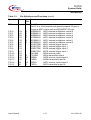
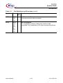
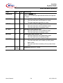
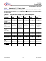
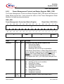
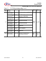
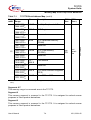
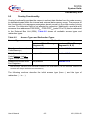
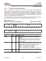
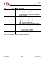
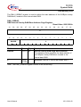
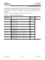
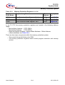
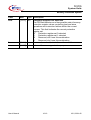
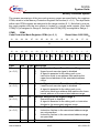
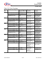
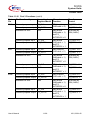
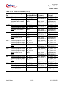
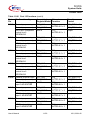
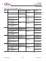
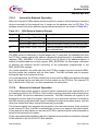
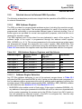
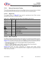
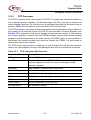
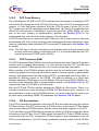
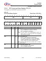
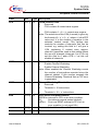
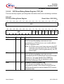
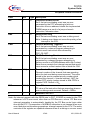
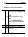
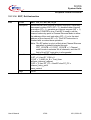
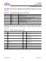
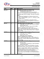
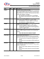
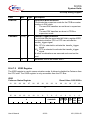
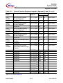
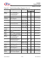
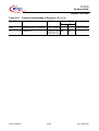
TC1775
System Units
Watchdog Timer
18.5
Handling the Watchdog Timer
This section describes methods of handling the Watchdog Timer function.
18.5.1
System Initialization
After any reset, the Watchdog Timer is put in Time-Out Mode, and
WDT_CON0.ENDINIT is 0, providing access to sensitive system registers. Changes to
the operation of the Watchdog Timer controlled by WDT_CON1 become effective only
after WDT_CON0.ENDINIT has been set to 1 again. Thus, changes to the WDT mode
bits in WDT_CON1 do not interfere with the Time-out operation of the Watchdog Timer
after reset. Table 18-10 shows the default contents of the Watchdog Timer registers.
Table 18-10 Watchdog Timer Default Values After Reset
Register
Default
Contents
Description
WDT_CON0 FFFC 0002H
Reload value is FFFCH, WDTPW is 0; WDT_CON0 is
locked (WDTLCK = 1); ENDINIT is 0.
WDT_CON1 0000 0000H
Watchdog Timer disable request is 0; input clock request
set to fSYSCLK/16384.
WDT_SR
FFFC 001UH The Watchdog counter contains FFFCH (the initial
Time-out value); WDT is operating in Time-Out Mode
(WDTTO = 1); WDT is enabled (WDTDS = 0); input
clock is fSYSCLK/16384.
Bits WDTOE and WDTAE are set to 0 after a power-on,
a hard or a soft reset. In case of a reset caused by the
WDT, these two bits are set depending on the error
condition that caused the Watchdog reset.
Because the Watchdog Timer is in Time-Out Mode after reset, WDT_CON0.ENDINIT
must be set to 1 before the Time-out Period expires. This means that initialization of
ENDINIT-protected system registers must be complete before the expiration of the
Time-out Period, defined in Section 18.4.7.1. To set WDT_CON0.ENDINIT to 1, a Valid
Password Access to WDT_CON0 must be performed first. During the subsequent Valid
Modify Access, WDT_CON0.ENDINIT must be set to 1, which will exit Time-Out Mode.
The Watchdog Timer is switched to the operation determined by the new values of
WDTIS and WDTDS.
Note: The action described above must absolutely be performed during initialization of
the device to properly terminate this mode. Even if the Watchdog function will not
be used in an application and the WDT will be disabled, a valid access sequence
to the WDT is mandatory. Otherwise, the Watchdog counter will overflow,
Prewarning Mode will be entered, and a Watchdog reset will occur at the end of
the Time-out Period.
User’s Manual
18-22
V2.0, 2001-02