1
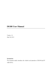
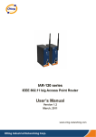
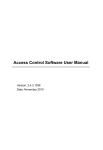
Web Server 3.0 User Manual Preface Without the permission of ZKSoftware INC., any copy is prohibited. All the specifications of the products mentioned here are subjected to the real objects. The company does not undertake that the real products are consistent with the information. The company does not undertake any dispute caused by the disagreement of actual technical parameter and this information. Besides, the company is not responsible to notice in advance. The other brand and product mentioned in this file mean the company ( possessing corresponding brand and product ) or its manufactured products。The company does not possess any privilege of the brand and product belonging to other companies. Remote data capturing system on Web Server is based on TCP/IP standard network structure. WEB page request is adopted to process and manage data. It is out of region restriction and it is not necessary to install other software. It can download and manage the data in fingerprint terminal remotely online through IE, NETSCAPE and other browsers. Then it makes various statistic statements for enterprise management and decisionmaking, achieving information synchronized any time any where and realizing highefficient management. CONTENTS 1. Log in Web Server ...............................................................................1 2. System Management............................................................................2 2.1 Exit from Web Server ................................................................2 2.2 Device Status .............................................................................2 3. User report ...........................................................................................4 3.1 Export the report ........................................................................4 3.2 Query records ............................................................................6 3.3 Realtime monitor .......................................................................7 4. User Administration.............................................................................8 4.1 Department management ...........................................................8 4.2 User Management ......................................................................9 4.2 Add User .................................................................................. 11 5. Access parameter setting....................................................................14 5.1 Access Parameter Setting.........................................................15 5.2 Weigand Setting.......................................................................16 5.3 Antipassback setting ...............................................................18 5.4 Time Zone................................................................................20 5.5 Group .......................................................................................22 5.6 Lock Group..............................................................................24 6. System Setting ...................................................................................27 6.1 TCP/IP Setting .........................................................................27 6.2 WIFI Setting ............................................................................28 6.3 Time setting .............................................................................30 6.4 Password..................................................................................33 7. Terminal.............................................................................................34 7.1 Backup .....................................................................................34 7.2 Restore .....................................................................................34 7.3 Update......................................................................................35 7.4 Download.................................................................................36 7.5 Open Door ...............................................................................38 7.6 Reboot......................................................................................38 Appendix 1 how to connect a terminal unit to network.........................40 1. Log in Web Server 1、When Web Server is used, device’s IP address should be set firstly. 2. Input http://192.168.1.234 in IE address column. Press ENTER to get the following picture: 3. To ensure system safe, ID verification needs to be done before entering system. The default account of super administrator: administrator; password: 123456 (which can be modified after entering the system). + Notice: 1 1. The administrator account can’t be modified. 2. The password can be modified. Capital & small letters are used for password. The way to modify, please refer to 6.4 Password. 2. System Management 2.1 Exit from Web Server If you want to exit from the system, click “Terminal” à “Login off” to exit to the login in window. 2.2 Device Status After entering into Web Server, system will display the basic information and the statuses of some functions about this device. Or click “Terminal” à “Status” as below shown: 2 The device information includes: device name, serial number, device date, IP address, user capacity, record capacity, finger capacity; as well as the status information of some functions. + Notice: 1. After modifying the information of device such as IP address etc., it is required to restart the device, then view the relate information of the device by visiting the web server. 2. When there is no access control function in device, the ‘Lock’ in Status will display ‘Disable’, and the ‘Access Control’ in left menu column will hide automatically. 3 3. User report 3.1 Export the report [function introduction] export in&out records of specified personnel during some period. [operating steps] 1. Click “User report”à“Report” to open the Report page: 2. Input the date range of report 1) Lay out period’s dropdown list, and select the date range. 4 2) If you want to selfdefine the date range, select the Date. Input the date range by selecting in the selection area of time zone. 3. Specify the personnel to be queried Tick the check box in the front of the personnel list. 4. Click ‘Search’ to display the in&out records according with conditions on the new page. If you want to view more details, click the right “More” to display more in new page: 5 3.2 Query records [function introduction] Query all inout records of specified personnel. [operating steps] 1. Click “User report’ à “Query” to open the Query window; 2. Specify the personnel to be queried 1) Tick the check box in the front of personnel list. 3. Click ‘Search’ to display the inout records according with conditions on the new page. 6 3.3 Realtime monitor [function introduction] Realtime monitor all inout records of current device. [operating steps] 1. Click “User report” à “Monitor”, and enter into the monitor page; 2. System will display the got realtime records on the screen. 7 4. User Administration 4.1 Department management [function introduction]Query, modify and delete the department that has existed in the system. [operating steps] 1. Click “User Administration”à “Department” to display the department information in the right page. 2. Add a department 1) Input the new department name in the textbox of Department Name. 2) After inputting, click “Add” button, the new added department is displayed in the list. 3. Delete a department 8 1) Click the ‘Delete’ button in the same line with the department that you want to delete, then the department is deleted from the system. 4.2 User Management [function introduction] Query, modify and delete the personnel that have existed in the system. [operating steps] 1. Click “User Administrator”à “User” to display all staff information in the page; 2. Query personnel 1) Select the department, which the personnel is belong to, in the dropdown department list. 2) Input the ID in ID number column and click “Search” button, then the personnel according with conditions will be displayed in the list. 9 3. Modify personnel’s information 1) Click ‘Modification’ on the line where the personnel is to enter editing interface. Remark: If there is no access control function in device, items of group, privilege and so on will hide automatically. 2) In editing interface, the ID number can only be digits and can not be the same with the other ID and the ID range is in 19 bits. Except for ID, the other operations are the same as those of “Add User”. 3) During modifying, click the “Reset” button in the leftdown corner to restore to the original information, or click “Add” button to return to the User page, then the modified personnel information is displayed in the list. 4. Delete the personnel’s information Click ‘Delete’ on the line where the personnel is to delete his information from the system. 10 4.3 Add User [function introduction]Add a new employee to the system, and specify his access control privilege. [operating steps] 1.Click “User administrator”à“Add user”; Remark: If there is no access control function in device, items of group, privilege and so on will hide automatically. 2. Input new user's information according to the page clues. 1) Don’t make the work number in collision (the work number is the digit from 1bit to 9 bits). Input the personnel’s name (8 characters or 4 Chinese characters at most) 2) Select user privilege (privilege for user to operate device). 3) Select welldefined group in access control setting (group 1 by default). 11 If select the corresponding group number, then the user will use the set time zone of this group by default. If not using group is selected, then another 3 time zones (‘or’ is among them) will be selected. Only in these 3 time zones, can the user have access control privilege. 4) The personnel who use password or card can input these two items. 5) Click “Add” after information filling is complete. 3. For example 1) User uses group time zone The above setting shows: No. 9 personnel “aa” belongs to group 2 and use the time zone of Group4. 2) User does not use group time zone. 12 The above setting shows: No. 9 personnel “aa” does not use group. He uses individual access control time zones, namely time zone 1 and time zone 29. 13 5. Access parameter setting Remark: Only the device with access control function has this function. 14 5.1 Access Parameter Setting [function introduction] the basic parameter settings and the advanced parameter settings of access control [operating steps] 1. Click “Access control” à “Access”; 2. According to the requirements to set parameters 1) Basic parameters setting Lock: the time used to control unlocking. The minimum unit is 20ms, and the default is 100ms. Door Sensor Delay: before starting alarm, there is a period of time after door opens, and this period of time is the door sensor delay. Door Sensor Mode: normally open, normally close and none. Error Times: when the number of unverified times is beyond the setting value, the system will generate a alarm signal. 15 2) Duress parameters setting: user can specify an enrolled fingerprint in the system as a duress fingerprint. In any case, this fingerprint identification will generate a duress alarm. Duress alarm delay: after the duress alarm signal is generated, you can define a period of time (0255 seconds) before outputting the alarm signal directly. The default value is 10. Alarm mode: 1:1、 1:N and password. User can select one or several. 3. After setting, click “OK”,then restart the device to make the settings take effect. 5.2 Weigand Setting [function introduction] Weigand out, Weigand in, as well as the reader selection under the format of the antipassback Weigand. [operation steps] 1. Click “Access Control” à “Wiegand Setting”; 16 2. According to requirements to set parameters 1) Wiegand out settings: Wiegand Format: since the welldefined formats built in the system, don’t need users to designate the total bit length as well as each information’s location. Two formats of Wiegand 26 and Wiegand34, you can select from the dropdown list. Wiegnd Pulse Width: the default pulse width sent by the Wiegand is 100 µs, but if the controller can not receive Wiegand, please adjust among the range from 1 to 999. Wiegand Pulse Interval: the default value is 900, and the adjustable range is from 1 to 999. 2) Wiegand in settings: Wiegand Bits Count: the output length of current format Wiegand Format: the user defined Wiegand in format, if user selects the standard Wiegand 26 or Wiegand 34, needs not to input the format string, if other formats, user needs to list the corresponding format string. 17 Wiegand Pulse Width: the default pulse width sent by the Wiegand is 100µs, but if the controller can not receive the Wiegand, the adjustable range is from 1 to 999. Wiegand Pulse Interval: the default value is 900, and the adjustable range is from 1 to 999. 3) The reader selection of antipassback Wiegand Wiegand Format: select the external reader supported by device in the case that the status of antipassback is on. 3. After setting, click “Set” in the bottom left corner, then restart the device to make the settings take effect. 5.3 Antipassback setting [function introduction] In order to prevent someone enters into the door but doesn’t go out by following the other person, you can use this function to avoid the safety hazard. The door can not be opened unless the out&in records are matched. This function needs two machines to cooperate and realize. One machine is installed indoors (called as “Host” in the followings), and the other machine is installed outdoors (called as “Client” in the followings). Two machines can communicate through Wiegand signal. 18 [operating steps] 1. Click “Access Control” à “Antipassback”; 2. The selections of antipass back mode. There are 4 selections: out antipassback, in antipassback, in&out antipassback, no antipassback, none and save. Out antipassback: only the last record of user is the in record, does the door open. The first verification is able to open the door. In antipassback: only the last record of user is the out record, does the door open. The first verification is able to open the door. Out&in antipassback: only the out&in records are in accordance, does the door open. The first verification is able to open the door. None and save: only the verification is passed between host and 19 Client, does the door open. No antipassback but reserve the status. 3. Master State Three selections: control in, control out, none. Control in: when set as this value, the records verified in this machine are the in records. Control out: when set as this value, the records verified in this machine are the out records. None: when set as this value, that is to close the antipassback function in this machine. 4. After setting, click the downleft “OK” button, then restart the device to make the settings take effect. 5.4 Time Zone [function introduction]Add and modify access control time zone which may be used by personnel. Time zone is the smallest time zone unit of access control setting. The whole system can define 50 time zones at most. Every time zone defines seven time intervals, namely a week. Every interval is the efficient time zone in 24 hours every day. Every user can set 3 time zones at most. “or” exists in the three time zones. It is efficient only if verification time can satisfy one of them. The format of every time interval in time zone is HH:MMHH:MM. That is, it is exact to minute. It means whole day forbidden if end time is smaller than start time (23:57 23:56) . And it means that the interval is efficient is end time is bigger than start time (00:00 23:59). Efficient time zone for user unlocking: whole day open (00: 20 0023:59)or end time is bigger than start time. [operating steps] 1.Click “Access Control”à“Time Zone”; 2. Add time zone 1) Lay out dropdown list of time zone number, and select the time zone number which does not exist in the list. 21 The time zone (which can be selected from the system) number range is 1—50. 2) Input time range (in time zone) to open the door. The above setting shows that the door can be open whole day from Monday to Friday, but opendoor is forbidden on Saturday and Sunday. 3) After inputting time zone information, click “OK” to save time zone setting, and the new time zone will be seen in the list. 3. Edit time zone 1) Lay out dropdown list of time zone number, and then select time zone number that you want to edit. 2) Input new time range. 3) After inputting, click “OK” to save the setting. 5.5 Group [function introduction]Set opendoor time zone for 99 groups preset by the system. Group setting can group users. 99 groups are defined by the system. The new enrolled user belongs to group 1 by default. He can also be reallocated to other groups through ‘add user’ or ‘modify user information’. There are three time zones in group time zone, with ‘or’ existing among them. +Notice: In general, the device with blackwhite screen has defined 5 groups, and the device with color screen has defined 99 groups. They have the same functions. In this document, we set the colorscreen 22 device for example. [operating steps] 1. Click “Access Control” à “Group”; 2. Add group setting (1) Lay out dropdown list of time zone number, and select group number. 23 Group number which can be selected from the system ranges from 1 to 99. (2) Input opendoor time zone. The above setting shows the opendoor time zones for personnel in group 13 are time zone 1 & 29. (3) Click “OK” to save the setting after input, and the new group setting will be seen in the list. 3. Edit group 1) Lay out dropdown list of time zone number, and select group number that you want to edit. 2) Input opendoor time zone. 3) Click “OK” to save and cover the setting after input. 5.6 Lock Group [function introduction] Set 10 unlocking combinations preset by the system. Unlocking combination directly shows unlocking control. To prevent all enrolled users unlocking, make no settings for 10 unlocking combinations. Unlocking combination setting is to define different unlocking combination. Every combination is made up of different groups. Unlocking combination directly use group number, without considering user verification order among various groups. For example: “123” means at least three users (one user respectively from group 1, group 2 and group 3 at least) can unlock after passing verification together. “4” shows that a single user in group 4 can unlock after passing verification. 24 The system can define 10 unlocking combination at most synchronously. Unlocking can be done only if user verification accords with one of them. + Notice: The system’s initial default unlocking combination is “1” (namely the new enrolled user can unlock by default). [operating steps] 1. Click “Access Control” à “Lock Group”; 2. Unlocking combination setting Tick the corresponding check box in the list to define the corresponding unlocking combination. 25 The above setting shows that 3 unlocking combinations are set. The group 1 is that unlocking can be done by successful verification of personnel in group 28, group 29, group 1. The group 2 is that unlocking can be only done by successful verification of personnel in group 1. The group 10 is that unlocking can be done by successful verification of personnel in the group 99. + Notice: the range of the unlocking combination is from 1 to 99. 3. Set unlocking combination, and click “OK” to save. 26 6. System Setting 6.1 TCP/IP Setting [function introduction] Set the TCP/IP communication parameters, which are used in the communications between device and PC, by software settting. [operating steps] 1. Click “Setting” à “TCP/IP”; 2. Input the device’s IP address, Subnet Mask, Default Gateway. IP address: the default IP is 192.168.1.201, and you can modify according to the actual. Subnet Mask: the default subnet mask is 255.255.255.0, and you can modify according to the actual. Default Gateway: the default gateway is 0.0.0.0, and you can modify it according to the actual. 3. Click “OK” to write parameters into the device. The terminal device will restart automatically to make the changes take effect. If not restart, please restart the device by manual. 27 6.2 WIFI Setting [function introduction] Set the WIFI parameters, which are used in wireless communications, by software setting. Before the device is used in wireless device, as for 802.11 network, the other physical components such as access point, distribution system, wireless medium must exist. You must know the SSID (network identification name) used to access network. Network identification ID: the network identification name used to access wireless network. (Distinguish the capital and small letter) Network mode: here there are two modes, infrastructure model and Ad-hoc Model. The first corresponds to the starstructure network, and the second corresponds to the peertopeer network. Identification mode: four modes of OPEN, SHARED, WEPAUTO, WPANONE are included by infrastructure model and Adhoc model. Encryption mode: two modes of WEP (wired equivalent privacy) and WPA (WIFI protested access). This device’s IP address: If in 802.11 wireless network, has a function to distribute the address dynamically (DHCP). Otherwise, input the correct IP address, subnet mask etc. in the specified IP window. [operating steps] 1. Click “Setting” à “WIFI Setting”; 28 2. Activate WIFI, there are two items of “Activate” and “Disable” for selection. If select “Activate”, the wireless terminal will be activated, then you can configure the access point in 802.11 network. If select “Disable”, the wireless terminal will be disabled, then the user can set the way to connect the device and IP of wireless network. 3. Input the identification name of wireless network in the textbox of Wireless Network SSID, and select the corresponding parameters in the dropdown lists of wireless mode, authentication mode, and encrypt type. 4. Set passwords: According to the authentication mode and encryption type, there are two ways of WEP and WPA to set passwords. WEP password: Password length: four options to select the password length Password: input the password complying with the conditions. 29 + Notice: If four passwords are set well in the WEP column, only the selected password is valid. WPA password: Input the password complying with the conditions. 5. The specified IP Specify the IP of device in wireless network. No relation with the network setting in communication setting. 6. After setting, click “OK” button, then restart the device to make the settings take effect. 6.3 Time setting [function introduction] Calibrate the device time and set the daylight saving time. [function introduction] 1. Click “Setting” à “Date/Time”; 30 2. Calibrate the device time Two ways to calibrate: auto and manual. If select “Auto” in Adjust mode, the device time will synchronize with the PC time. If select “Manual”, the user will set the device time manually. In two textboxes of New Date/Time, input the new date and time. The date format is YYYYMMDD and the time format is HH:MM:SS. After setting, click “OK” in Date/Time. Note: “PC Date” is only as a reference to calibrate time. 3. Set daylight saving time In the dropdown list of Daylight Saving model, select “ON” to open the daylight saving time, or select “OFF” to close the daylight saving time. If select “ON” in model, there are two models of daylight saving time: model1 and model2. If select model1, it indicates to set the daylight saving time as MMDD HH:MM format, and this model is the default model. If select model2, it indicates to set the daylight saving time as MM WS WK HH:MM format. 31 The value range of WS is: 16, 1 indicates the first week and 2 indicates the second week, and so on. The value range of WK is: 06, 0 indicates Sunday and 1 indicates Monday, and so on. For example: We set an example as 200891 4:00 (Sunday, the first week, September 2008) to introduce the two modes: + Notice: 1. If the start month of daylight saving time is bigger than the end time of daylight saving time, it indicates to straddle over year. For example: start 200791 4:000, end 200841 4:00. 2. If select model2, set the start time of daylight saving time: Sunday, the sixth week, September, 2007. Then in 2008, since no the sixth week but fifth week in September, system will regard the time of last Sunday of that month as the start time to enter into the daylight saving time. 3. If set the start time of daylight saving time as Monday, the first week, September, 2008. Then in 2009, since the first day of September is Tuesday not Monday, system will find the first Monday in that month automatically in this case. +Notice: The colorscreen device can only use model 1. 32 6.4 Password [function introduction] Modify the administrator password used to login in Web server. [operating steps] 1. Click “Setting” à “Password”; 2. Input new password twice, and click “OK” button. 3. After modifying, need to log off the system and log in again. 33 7. Terminal 7.1 Backup [function introduction] Backup system data and user data, include configuration information of system parameters and user information as well as in&out records. [operating steps] 1.Click “Terminal” à “Backup”; 2. Select Backup System Data or Backup User data, click “Backup” button to pop up the message box. Save data to the designated path. 7.2 Restore [function introduction] Restore data to the device, the data must be the previous BIN data backed up through the backup function. 34 [operating steps] 1. Click “Terminal” à “Restore”; 2. Click “Browse” button, then select the backup data saved in the local. 3. Click “Restore” button to restore data to the device. 7.3 Update [function introduction] Update the firmware data in device, and update the data package as BIN format. [operating steps] 1. Click “Terminal” à “Update”; 35 2. Click “Browse” button, then select the firmware data saved in the local. 3. Click “Update Firmware” button to update the firmware of device. 7.4 Download [function introduction] Modify the password of current user who has logged in. [operating steps] 1. Click “Terminal” à “Download”; 36 2. Input the date range of downloading. 1) Pop up the dropdown list of period, and select the desired date range. 2) If you want to selfdefine the time range, select the Date. Input the date range by selecting the date in time selection area. 37 3. Designated personnel 1) Tick the check box at the front in the personnel list. 4. Click “Download” button to pop up the Save message box, after designating the path, download the in&out records complying with the conditions to the local PC. 7.5 Open Door [function introduction] Modify the password of current user who has logged in. [operating steps] 1. Click “Terminal” à “Open Door” 2. System informs “The door is open”. 7.6 Reboot [function introduction] Reboot the device remotely by Web server. 38 [operating steps] 1. Click “Terminal” à “Reboot” 2. System informs “Device is rebooting, please connect device later”. 39 Appendix 1 how to connect a terminal unit to network 1. Terminal unit requirement Web Server function, namely device’s selective function, needs firmware support of device. J Tip:Please consult technicians or contact business representatives of company if you need this function. 2. Terminal unit parameters 1)enter device’s menu—setting—communication setting to find the following items: IP address Network speed rate Gateway address Subnet mask IP address: allocate IP address for the device. Network speed rate: select corresponding network speed rate according to actual network environment. If access needs crossing network segment, gateway address and subnet mask need to be set. 3. Set device’s parameters according to different network environment 40 1)If PC and terminal unit are in the same network segment of a LAN. “IP address” and “network speed rate” need to be set. For example: PC’s IP is 192.168.1.100, and device’s IP is 192.168.1.201. When logging in Web server on PC, input 192.168.1.201 in browser’s address column. 2)If PC and terminal unit are in the same LAN, but in different network segment. IP address, network speed rate, gateway and subnet mask need to be set. 3)If PC and terminal unit are not in the same LAN, terminal unit must possess a public network IP for PC to access. 41