1
OPERATING MANUAL
TS100-3000-A
S
TS100 TelScout
®
Metallic Time-Domain Reflectometer
Tempo
e pop Customer
Custo e Training
a g & Technical
ec ca Support
Suppo
pp t
TEMPO — TS100 TELSCOUT®
Metallic Time-Domain Reflectometer
OPERATING MANUAL
CUSTOMER TRAINING & TECHNICAL SUPPORT
NOTICE: This document is an unpublished work
protected by United States copyright laws and is
proprietary to Tempo. Disclosure, copying,
reproduction, merger, translation, modification,
enhancement or use by anyone other than
authorized employees or licensees of Tempo and
its affiliate companies without prior consent of
Tempo is prohibited.
Copyright © 2002
Tempo - a Textron Company. All rights reserved.
Tempo Research, a Delaware Corporation
TS100-3000-A
Printed in U.S.A.
12/2/2002
Copyright © Tempo 2002. All Rights reserved.
Tempo products are covered by U.S. and foreign patents, issued and pending. Information in this
publication supercedes that in all previously published material. Specifications and price change
privleges reserved.
IBM is a registered trademark of International Business Machines.
Deskjet, Laserjet, and Thinkjet are registered trademarks of Hewlett Packard
PostScript is a registered trademark of Adobe Systems, Inc.
Epson is a registered trademark of Epson America, Inc.
Seiko is a registered trademark of Seiko Instruments, Inc.
Printed in the U.S.A.
Part Number TS100-3000-A (12/2/2002)
Tempo, 1390 Aspen Way, Vista, Ca 92083
Warning
This equipment generates, uses, and can radiate radio-frequency energy, and if not
installed and used in accordance with the instructions in the user manual, may cause
interference to radio communications. It has been tested and found to comply with the
limits for a Class A computing device pursuant to Subpart B of Part 15 of FCC Rules,
which are designated to provide reasonable protection against such interference when
operated in a commercial environment. Operation of this equipment in a residential area is
likely to cause interference, in which case, the user, at his or her own expense, will be
required to take whatever measures may be required to correct the interference.
WARRANTY SERVICE
CONTRACT INFORMATION
GENERAL WARRANTY PROVISIONS
Seller warrants to Buyer that products
furnished hereunder will be merchantable,
free from defects in design, material and
workmanship, fit and sufficient for the
purposes intended by Buyer, free from all
liens and encumbrances and will conform
to and perform in accordance with the
specifications set forth in this Agreement
for a period of One Year, commencing with
the date of acceptance thereof by Buyer.
Defective products will, at Buyer s option,
be either returned to Seller, or Seller s
Authorized Repair Agency, for repair or
replacement, with risk of in-transit loss and
damage borne and transportation charged
paid by Seller, or repaired or replaced by
Seller, or Seller s Authorized Repair
Agency, on site at Seller s expense. Unless
otherwise agreed upon by the parties,
Seller, or Seller s Authorized Repair
Agency, will complete repairs and ship the
repaired product within five (5) days of
receipt of the defective product or, at
Buyer s option, ship replacement product
within five (5) days after receipt of oral
notification from Buyer. Seller, or Seller s
Authorized Repair Agency, will bear the
risk of in-transit loss and damage and will
prepay and bear the cost of transportation
charges for shipments to Buyer of repaired
or replaced products. If requested by
Buyer, Seller, or Seller s Authorized Repair
Agency, at Seller s expense, will begin onsite repairs within three (3) days after
receiving verbal notification from Buyer.
If product returned to Seller, or Seller s
Authorized Repair Agency, or made
available to Seller, or Seller s Authorized
Repair Agency, on site for repair, as
provided for in this clause is determined to
be beyond repair, Seller, or Seller s
Authorized Repair Agency, will promptly
so notify Buyer and, unless otherwise
agreed to by the parties, ship replacement
product without charge within five (5) days
of such notification.
Any replacement, repair, modification,
installation or other service performed by
Seller, or Seller s Authorized Repair
Agency, pursuant hereto will be warranted
as herein provided based upon the date
performance of the service is completed
and accepted by Buyer for the remainder of
the unexpired period of the original
warranty or for a new period of one (1)
year, whichever is longer.
All services, if any, provided under this
Agreement will be provided in a fully
professional manner.
WORK HEREUNDER
It is understood that visits by
representatives of Seller or it s suppliers for
inspection, adjustment or other similar
purposes in connection with products
purchased hereunder will for all purposes
be deemed work hereunder and will be at
no charge to Buyer unless otherwise agreed
in writing with Buyer.
SPECIFIC WARRANTY PROVISIONS
FACTORY WARRANTY:
Tempo warrants all products against
defects in material or workmanship for a
period of one year from date of shipment to
the original purchaser. All units returned to
a Tempo authorized repair center, delivery
charges prepaid, that are deemed defective
under this warranty will be replaced or
repaired at Tempo s option. This warranty
shall not apply to any defect, failure or
damaged caused by improper use or
inadequate maintenance. This warranty
does not apply to worn or damaged
accessories such as test leads, batteries and
soft cases. Calibration is not covered under
factory warranty.
Product sold through distribution carries a
15-month warranty due to turn around
time.
CONTRACTED SERVICE:
Tempo offers contracted warranty for
specific products. The Sales Department
negotiates these contracts at the time of
purchase. Such contracts are customer and/
or marketing driven. Contracts are
product/customer specific.
PCB (MODULE) EXCHANGE:
It is the discretion of Tempo to exchange
defective or damaged PCB modules with
refurbished PCB modules.
NON-WARRANTY REPAIRS:
Tempo will charge time and material for all
product repairs that are non-warranty.
Any Tempo manufactured unit that is
received with a broken seal (opened by
someone other than Tempo authorized
personnel) will be considered non-warranty
and repaired as such.
SPARE PARTS:
Spare parts are sold to Tempo authorized
repair centers only.
Tempo considers spare parts to be any
internal part that the unit must be opened to
have replaced.
ACCESSORIES:
Accessories can be ordered through
Tempo s sales department or distribution
centers. Contact our sales department for a
list of accessories per product.
Tempo considers accessories to be any item
that is not required for unit operation, with
the exception being test leads and cables. .
I.e.: straps, cases, software.
EXTENDED WARRANTY:
Extended warranty is available at the
buyer s option. Both options and the
pricing are contained in section III.
WARRANTY ON REPAIRED
PRODUCTS:
Tempo offers a 90-day warranty against
defects in material or workmanship for
repaired products. Extended repair
warranty may be available for select
customers and is negotiated by sales
department.
FLAT RATE REPAIR CONTRACTS:
Flat rate repair contracts for pricing and
product coverage are available for nonwarranty repairs. The sales department
negotiates these contracts.
1390 Aspen Way — Vista, CA 92083
760-598-8900 . 800-642-2155 .
Fax 760-598-5634
M — F . 7:00 a.m. — 4:30 p.m. . Pacific Time
Unit 3, Maesglas Industrial Estate
Newport, NP20 2NN, UK
+44 (0) 1633 223552 .
Fax +44 (0) 1633 223948
www.tempo.Textron.com
Table of Contents
List of Figures . . . . . . . . . . . . . . . . . . . . . . . . . . . . . . . . . . . . . . . . . . . . . . . . . . . iv
List of Tables . . . . . . . . . . . . . . . . . . . . . . . . . . . . . . . . . . . . . . . . . . . . . . . . . . . . vi
Preface
Manual Structure . . . . . . . . . . . . . . . . . . . . . . . . . . . . . . . . . . . . . . . . . . . . . . . . . vii
Manual Conventions . . . . . . . . . . . . . . . . . . . . . . . . . . . . . . . . . . . . . . . . . . . . . . vii
Related Manuals . . . . . . . . . . . . . . . . . . . . . . . . . . . . . . . . . . . . . . . . . . . . . . . . . vii
Safety . . . . . . . . . . . . . . . . . . . . . . . . . . . . . . . . . . . . . . . . . . . . . . . . . . . . . . . . . viii
Power Source . . . . . . . . . . . . . . . . . . . . . . . . . . . . . . . . . . . . . . . . . . . . . . . viii
Grounding the Instrument . . . . . . . . . . . . . . . . . . . . . . . . . . . . . . . . . . . . . viii
Do Not Operate in Explosive Atmosphere . . . . . . . . . . . . . . . . . . . . . . . . viii
Do Not Remove Covers or Panels . . . . . . . . . . . . . . . . . . . . . . . . . . . . . . . viii
Disposal of Batteries . . . . . . . . . . . . . . . . . . . . . . . . . . . . . . . . . . . . . . . . . viii
Getting Started
Product Description . . . . . . . . . . . . . . . . . . . . . . . . . . . . . . . . . . . . . . . . . . . . . . 1–1
Key Specifications . . . . . . . . . . . . . . . . . . . . . . . . . . . . . . . . . . . . . . . . . . . . . . . 1–1
Accessories . . . . . . . . . . . . . . . . . . . . . . . . . . . . . . . . . . . . . . . . . . . . . . . . . . . . 1–2
Quick Check Out . . . . . . . . . . . . . . . . . . . . . . . . . . . . . . . . . . . . . . . . . . . . . . . . 1–2
For First–Time Operators . . . . . . . . . . . . . . . . . . . . . . . . . . . . . . . . . . . . . . . . . 1–3
Operation Basics
At a Glance . . . . . . . . . . . . . . . . . . . . . . . . . . . . . . . . . . . . . . . . . . . . . . . . . . . . 2–1
General Controls and Indicators . . . . . . . . . . . . . . . . . . . . . . . . . . . . . . . . 2–1
POWER . . . . . . . . . . . . . . . . . . . . . . . . . . . . . . . . . . . . . . . . . . . . . . . . . 2–1
HELP . . . . . . . . . . . . . . . . . . . . . . . . . . . . . . . . . . . . . . . . . . . . . . . . . . 2–2
LCD . . . . . . . . . . . . . . . . . . . . . . . . . . . . . . . . . . . . . . . . . . . . . . . . . . . 2–2
Softkeys: . . . . . . . . . . . . . . . . . . . . . . . . . . . . . . . . . . . . . . . . . . . . . . . 2–2
Scroll Controls . . . . . . . . . . . . . . . . . . . . . . . . . . . . . . . . . . . . . . . . . . . . . . 2–2
Connectors . . . . . . . . . . . . . . . . . . . . . . . . . . . . . . . . . . . . . . . . . . . . . . . . 2–2
AC Adapter/Charger:. . . . . . . . . . . . . . . . . . . . . . . . . . . . . . . . . . . . . 2–2
TEST . . . . . . . . . . . . . . . . . . . . . . . . . . . . . . . . . . . . . . . . . . . . . . . . . . 2–3
REFERENCE . . . . . . . . . . . . . . . . . . . . . . . . . . . . . . . . . . . . . . . . . . . . . 2–3
Printer . . . . . . . . . . . . . . . . . . . . . . . . . . . . . . . . . . . . . . . . . . . . . . . . . 2–3
Power Indicators/Low Battery Warning . . . . . . . . . . . . . . . . . . . . . . . . . . 2–3
Arrow/Star Key . . . . . . . . . . . . . . . . . . . . . . . . . . . . . . . . . . . . . . . . . . . . . 2–3
Softkeys . . . . . . . . . . . . . . . . . . . . . . . . . . . . . . . . . . . . . . . . . . . . . . . . . . . 2–3
Instrument Settings . . . . . . . . . . . . . . . . . . . . . . . . . . . . . . . . . . . . . . . . . . 2–4
Backlight . . . . . . . . . . . . . . . . . . . . . . . . . . . . . . . . . . . . . . . . . . . . . . . . . . . . . . 2–4
Measurement Mode . . . . . . . . . . . . . . . . . . . . . . . . . . . . . . . . . . . . . . . . . . . . . . 2–4
TS100 TelScout User Manual
i
Contents
Auto Control . . . . . . . . . . . . . . . . . . . . . . . . . . . . . . . . . . . . . . . . . . . . . . .2–4
Manual Control . . . . . . . . . . . . . . . . . . . . . . . . . . . . . . . . . . . . . . . . . . . . .2–4
Display Organization in Measurement Mode . . . . . . . . . . . . . . . . . . . . .2–5
Menu Mode . . . . . . . . . . . . . . . . . . . . . . . . . . . . . . . . . . . . . . . . . . . . . . . . . . . .2–5
Tutorial
General Instructions . . . . . . . . . . . . . . . . . . . . . . . . . . . . . . . . . . . . . . . . . . . . . .3–1
Setting Up the Instrument . . . . . . . . . . . . . . . . . . . . . . . . . . . . . . . . . . . . . . . . .3–1
Defining Cables . . . . . . . . . . . . . . . . . . . . . . . . . . . . . . . . . . . . . . . . . . . . . . . . .3–3
Setting Up the Printer . . . . . . . . . . . . . . . . . . . . . . . . . . . . . . . . . . . . . . . . . . . .3–4
Changing Contrast . . . . . . . . . . . . . . . . . . . . . . . . . . . . . . . . . . . . . . . . . . . . . . .3–6
Acquiring a Waveform . . . . . . . . . . . . . . . . . . . . . . . . . . . . . . . . . . . . . . . . . . .3–7
Saving a Waveform . . . . . . . . . . . . . . . . . . . . . . . . . . . . . . . . . . . . . . . . . . . . . .3–8
Displaying a Saved Waveform . . . . . . . . . . . . . . . . . . . . . . . . . . . . . . . . . . . . .3–9
Comparing an Active Waveform Against a Saved Waveform . . . . . . . . . . . .3–11
Comparing Two Active Waveforms . . . . . . . . . . . . . . . . . . . . . . . . . . . . . . . .3–12
Displaying the Difference of Two Waveforms . . . . . . . . . . . . . . . . . . . . . . . .3–13
Downloading a Waveform to a Personal Computer . . . . . . . . . . . . . . . . . . . .3–14
Uploading a Waveform from a Personal Computer . . . . . . . . . . . . . . . . . . . .3–16
Detecting Intermittent Faults . . . . . . . . . . . . . . . . . . . . . . . . . . . . . . . . . . . . . .3–16
Using the TS100 in Manual Mode . . . . . . . . . . . . . . . . . . . . . . . . . . . . . . . . . .3–18
Reference
Start–Up Display . . . . . . . . . . . . . . . . . . . . . . . . . . . . . . . . . . . . . . . . . . . . . . . .4–1
Waveform Displays . . . . . . . . . . . . . . . . . . . . . . . . . . . . . . . . . . . . . . . . . . . . . .4–1
Auto-Control Displays . . . . . . . . . . . . . . . . . . . . . . . . . . . . . . . . . . . . . . . .4–1
Waveform Expansion Display . . . . . . . . . . . . . . . . . . . . . . . . . . . . . . . . . .4–3
Dual-Waveform Display . . . . . . . . . . . . . . . . . . . . . . . . . . . . . . . . . . . . . .4–3
Difference of Two Waveforms . . . . . . . . . . . . . . . . . . . . . . . . . . . . . . . . .4–4
Manual-Control Display . . . . . . . . . . . . . . . . . . . . . . . . . . . . . . . . . . . . . .4–5
Menus . . . . . . . . . . . . . . . . . . . . . . . . . . . . . . . . . . . . . . . . . . . . . . . . . . . . . . . . .4–6
Setup Menu . . . . . . . . . . . . . . . . . . . . . . . . . . . . . . . . . . . . . . . . . . . . . . . .4–6
Test Type Menu . . . . . . . . . . . . . . . . . . . . . . . . . . . . . . . . . . . . . . . . . . . . .4–7
Printer Setup Menu . . . . . . . . . . . . . . . . . . . . . . . . . . . . . . . . . . . . . . . . . .4–8
More Setups Menu . . . . . . . . . . . . . . . . . . . . . . . . . . . . . . . . . . . . . . . . . . .4–9
Define Cables Menu . . . . . . . . . . . . . . . . . . . . . . . . . . . . . . . . . . . . . . . .4–10
Save Print Menu . . . . . . . . . . . . . . . . . . . . . . . . . . . . . . . . . . . . . . . . . . . .4–11
Upload/Download Menu . . . . . . . . . . . . . . . . . . . . . . . . . . . . . . . . . . . . .4–12
Text Entry . . . . . . . . . . . . . . . . . . . . . . . . . . . . . . . . . . . . . . . . . . . . . . . . . . . .4–13
Sample Waveforms . . . . . . . . . . . . . . . . . . . . . . . . . . . . . . . . . . . . . . . . . . . . .4–14
ii
TS100 TelScout User Manual
Contents
Appendix A: Specifications
Physical . . . . . . . . . . . . . . . . . . . . . . . . . . . . . . . . . . . . . . . . . . . . . . . . . . . . . .
Environmental . . . . . . . . . . . . . . . . . . . . . . . . . . . . . . . . . . . . . . . . . . . . . . . . .
Safety . . . . . . . . . . . . . . . . . . . . . . . . . . . . . . . . . . . . . . . . . . . . . . . . . . . . . . . .
Reliability . . . . . . . . . . . . . . . . . . . . . . . . . . . . . . . . . . . . . . . . . . . . . . . . . . . .
Power Source . . . . . . . . . . . . . . . . . . . . . . . . . . . . . . . . . . . . . . . . . . . . . . . . . .
Interface . . . . . . . . . . . . . . . . . . . . . . . . . . . . . . . . . . . . . . . . . . . . . . . . . . . . . .
Operational . . . . . . . . . . . . . . . . . . . . . . . . . . . . . . . . . . . . . . . . . . . . . . . . . . .
A–1
A–1
A–2
A–2
A–2
A–2
A–3
Appendix B: General–1
Power–up Information Messages . . . . . . . . . . . . . . . . . . . . . . . . . . . . . . . . . . .B–1
Error Messages . . . . . . . . . . . . . . . . . . . . . . . . . . . . . . . . . . . . . . . . . . . . . . . . .B–1
Service . . . . . . . . . . . . . . . . . . . . . . . . . . . . . . . . . . . . . . . . . . . . . . . . . . .B–2
User Serviceable Parts . . . . . . . . . . . . . . . . . . . . . . . . . . . . . . . . . . . . . . . .B–2
Tempo Repair Services . . . . . . . . . . . . . . . . . . . . . . . . . . . . . . . . . . . . . . .B–2
Inspection and Cleaning . . . . . . . . . . . . . . . . . . . . . . . . . . . . . . . . . . . . . . . . . .B–2
Inspection . . . . . . . . . . . . . . . . . . . . . . . . . . . . . . . . . . . . . . . . . . . . . . . . .B–2
Cleaning . . . . . . . . . . . . . . . . . . . . . . . . . . . . . . . . . . . . . . . . . . . . . . . . . . .B–2
Battery . . . . . . . . . . . . . . . . . . . . . . . . . . . . . . . . . . . . . . . . . . . . . . . . . . . . . . . .B–3
Options . . . . . . . . . . . . . . . . . . . . . . . . . . . . . . . . . . . . . . . . . . . . . . . . . . . . . . .B–3
Accessories . . . . . . . . . . . . . . . . . . . . . . . . . . . . . . . . . . . . . . . . . . . . . . . . . . . .B–8
Standard Accessories . . . . . . . . . . . . . . . . . . . . . . . . . . . . . . . . . . . . . . . . .B–8
Optional Accessories . . . . . . . . . . . . . . . . . . . . . . . . . . . . . . . . . . . . . . . . .B–8
Appendix C: TS100 Performance Checks
Required Equipment . . . . . . . . . . . . . . . . . . . . . . . . . . . . . . . . . . . . . . . . . . . . .C–1
Test Chart with Acceptable Tolerances . . . . . . . . . . . . . . . . . . . . . . . . . . . . . .C–2
Check Port Configurations . . . . . . . . . . . . . . . . . . . . . . . . . . . . . . . . . . . . . . . .C–2
Check Distance Readout . . . . . . . . . . . . . . . . . . . . . . . . . . . . . . . . . . . . . . . . . .C–5
Check Differential . . . . . . . . . . . . . . . . . . . . . . . . . . . . . . . . . . . . . . . . . . . . . . .C–6
Check Crosstalk . . . . . . . . . . . . . . . . . . . . . . . . . . . . . . . . . . . . . . . . . . . . . . . . .C–6
Check Dual Displays . . . . . . . . . . . . . . . . . . . . . . . . . . . . . . . . . . . . . . . . . . . . .C–7
Check Smoothing . . . . . . . . . . . . . . . . . . . . . . . . . . . . . . . . . . . . . . . . . . . . . . .C–8
Glossary
Index
TS100 TelScout User Manual
iii
Contents
List of Figures
iv
Figure 1-1:
Figure 1-2:
Install Test-Lead ID Rings on Test Leads . . . . . . . . . . . . . . . .1–2
Start-up Display . . . . . . . . . . . . . . . . . . . . . . . . . . . . . . . . . . . .1–2
Figure 2-1:
Figure 2-2:
Figure 2-3:
Front–Panel Controls, Indicators, and Connectors . . . . . . . . .2–1
Arrangement of Information on the Measurement Display . . .2–5
Arrangement of Information on a Typical Menu Display . . . .2–6
Figure 3-1:
Figure 3-2:
Figure 3-3:
Figure 3-4:
Figure 3-5:
Figure 3-6:
Figure 3-7:
Figure 3-8:
Figure 3-9:
Figure 3-10:
Figure 3-11:
Figure 3-12:
Figure 3-13:
Figure 3-14:
Figure 3-15:
Figure 3-16:
Figure 3-17:
Figure 3-18:
Figure 3-19:
Figure 3-20:
Figure 3-21:
Figure 3-22:
Figure 3-23:
Figure 3-24:
Figure 3-25:
Figure 3-26:
Figure 3-27:
Figure 3-28:
Figure 3-29:
Start–Up Display . . . . . . . . . . . . . . . . . . . . . . . . . . . . . . . . . . .3–1
Setup Menu . . . . . . . . . . . . . . . . . . . . . . . . . . . . . . . . . . . . . . .3–2
Auto–Control Measurement Display . . . . . . . . . . . . . . . . . . . .3–2
Define Cable Type Menu . . . . . . . . . . . . . . . . . . . . . . . . . . . .3–3
Text Entry Display . . . . . . . . . . . . . . . . . . . . . . . . . . . . . . . . . .3–3
Define Cables Menu . . . . . . . . . . . . . . . . . . . . . . . . . . . . . . . .3–4
Printer Setup Menu . . . . . . . . . . . . . . . . . . . . . . . . . . . . . . . . .3–5
Changing Baud Rate . . . . . . . . . . . . . . . . . . . . . . . . . . . . . . . .3–5
More Setups Menu . . . . . . . . . . . . . . . . . . . . . . . . . . . . . . . . . .3–6
Changing Contrast . . . . . . . . . . . . . . . . . . . . . . . . . . . . . . . . . .3–6
Auto–Control Measurement Display . . . . . . . . . . . . . . . . . . . .3–7
Save/Print Menu . . . . . . . . . . . . . . . . . . . . . . . . . . . . . . . . . . .3–8
Text Entry Display . . . . . . . . . . . . . . . . . . . . . . . . . . . . . . . . . .3–8
Save/Print Menu . . . . . . . . . . . . . . . . . . . . . . . . . . . . . . . . . . .3–9
Test Type Menu . . . . . . . . . . . . . . . . . . . . . . . . . . . . . . . . . . . .3–9
Selecting a Saved Waveform . . . . . . . . . . . . . . . . . . . . . . . . .3–10
Display of the Saved Waveform . . . . . . . . . . . . . . . . . . . . . .3–10
Test Type Menu . . . . . . . . . . . . . . . . . . . . . . . . . . . . . . . . . . .3–11
Test Pair / Saved Waveform Display . . . . . . . . . . . . . . . . . .3–11
Test Type Menu . . . . . . . . . . . . . . . . . . . . . . . . . . . . . . . . . . .3–12
Test and Reference Dual Waveform Display . . . . . . . . . . . .3–13
Test Type Menu . . . . . . . . . . . . . . . . . . . . . . . . . . . . . . . . . . .3–13
Dual–Waveform Difference Display . . . . . . . . . . . . . . . . . . .3–14
Save/Print Menu . . . . . . . . . . . . . . . . . . . . . . . . . . . . . . . . . .3–15
Upload/Download Menu . . . . . . . . . . . . . . . . . . . . . . . . . . . .3–15
Test Type Menu . . . . . . . . . . . . . . . . . . . . . . . . . . . . . . . . . . .3–17
Intermittent Measurement Display . . . . . . . . . . . . . . . . . . . .3–17
Setup Menu . . . . . . . . . . . . . . . . . . . . . . . . . . . . . . . . . . . . . .3–18
Manual–Control Measurement Display . . . . . . . . . . . . . . . . .3–19
Figure 4-1:
Figure 4-2:
Figure 4-3:
Figure 4-4:
Figure 4-5:
Figure 4-6:
Figure 4-7:
Figure 4-8:
Figure 4-9:
Start–Up Display . . . . . . . . . . . . . . . . . . . . . . . . . . . . . . . . . . .4–1
Auto–Control Measurement Display . . . . . . . . . . . . . . . . . . . .4–2
Expanded Waveform Display . . . . . . . . . . . . . . . . . . . . . . . . .4–3
Test and Reference Dual–Waveform Display . . . . . . . . . . . . .4–4
Dual–Waveform Difference Display . . . . . . . . . . . . . . . . . . . .4–4
Manual–Control Measurement Display . . . . . . . . . . . . . . . . . .4–5
Setup Menu . . . . . . . . . . . . . . . . . . . . . . . . . . . . . . . . . . . . . . .4–6
Test Type Menu . . . . . . . . . . . . . . . . . . . . . . . . . . . . . . . . . . . .4–7
Printer Setup Menu . . . . . . . . . . . . . . . . . . . . . . . . . . . . . . . . .4–8
TS100 TelScout User Manual
Contents
Figure 4-10:
Figure 4-11:
Figure 4-12:
Figure 4-13:
Figure 4-14:
Figure 4-15:
Figure 4-16:
Figure 4-17:
Figure 4-18:
Figure 4-19:
Figure 4-20:
Figure 4-21:
Figure 4-22:
Figure 4-23:
Figure 4-24:
More Setups Menu . . . . . . . . . . . . . . . . . . . . . . . . . . . . . . . . . 4–9
Define Cables Menu . . . . . . . . . . . . . . . . . . . . . . . . . . . . . . . 4–10
Save/Print Menu . . . . . . . . . . . . . . . . . . . . . . . . . . . . . . . . . . 4–11
Upload/Download Menu . . . . . . . . . . . . . . . . . . . . . . . . . . . . 4–12
Text Entry Display . . . . . . . . . . . . . . . . . . . . . . . . . . . . . . . . 4–13
Typical Open . . . . . . . . . . . . . . . . . . . . . . . . . . . . . . . . . . . . . 4–14
Typical Short . . . . . . . . . . . . . . . . . . . . . . . . . . . . . . . . . . . . . 4–15
Split Pairs (Crosstalk Mode) . . . . . . . . . . . . . . . . . . . . . . . . . 4–15
Split Pairs (Pair–Comparison Mode) . . . . . . . . . . . . . . . . . . 4–16
Split Pairs with Gain Increased . . . . . . . . . . . . . . . . . . . . . . . 4–16
Wet Section . . . . . . . . . . . . . . . . . . . . . . . . . . . . . . . . . . . . . . 4–17
Wet Section with Gain Increased . . . . . . . . . . . . . . . . . . . . . 4–17
Typical Load Coil . . . . . . . . . . . . . . . . . . . . . . . . . . . . . . . . . 4–18
Typical Bridged Tap . . . . . . . . . . . . . . . . . . . . . . . . . . . . . . . 4–18
Bridged Tap and End of Cable . . . . . . . . . . . . . . . . . . . . . . . 4–19
Figure B-1:
Figure B-2:
Figure B-3:
Figure B-4:
Figure B-5:
Figure B-6:
Start–Up Display . . . . . . . . . . . . . . . . . . . . . . . . . . . . . . . . . . .B–4
Setup Menu for Twisted Pair . . . . . . . . . . . . . . . . . . . . . . . . .B–5
More Setups Menu . . . . . . . . . . . . . . . . . . . . . . . . . . . . . . . . .B–5
Setup Menu for Coax . . . . . . . . . . . . . . . . . . . . . . . . . . . . . . .B–6
Define Cables Menu for Coax . . . . . . . . . . . . . . . . . . . . . . . .B–6
Test Type Menu for Coax . . . . . . . . . . . . . . . . . . . . . . . . . . . .B–7
Figure C-1:
Figure C-2:
Figure C-3:
Figure C-4:
Figure C-5:
Figure C-6:
Figure C-7:
Figure C-8:
Figure C-9:
Figure C-10:
Figure C-11:
Figure C-12:
Typical Equipment Setup for Performance Verification . . . .C–1
Start–up Display Showing Power Icons . . . . . . . . . . . . . . . . .C–2
Waveform without Test Leads . . . . . . . . . . . . . . . . . . . . . . . .C–3
Waveform with Test Leads . . . . . . . . . . . . . . . . . . . . . . . . . . .C–3
Waveform with 1000–ft Cable on Test Port . . . . . . . . . . . . . .C–4
Waveform with Range Increased (Test Pair) . . . . . . . . . . . . .C–4
Reference Pair Waveform . . . . . . . . . . . . . . . . . . . . . . . . . . . .C–5
Waveform with Cursor at Edge of Reflection . . . . . . . . . . . .C–5
Waveform Difference on 1000–ft Cable . . . . . . . . . . . . . . . . .C–6
Crosstalk on 1000–ft Cable . . . . . . . . . . . . . . . . . . . . . . . . . . .C–7
Test and Reference Pairs on 1000–ft Cable . . . . . . . . . . . . . .C–8
Test and Reference Pairs on 1000–ft Cable Showing
Differences . . . . . . . . . . . . . . . . . . . . . . . . . . . . . . . . . . . . . . .C–8
Noise . . . . . . . . . . . . . . . . . . . . . . . . . . . . . . . . . . . . . . . . . . . .C–9
Maximum Smoothing . . . . . . . . . . . . . . . . . . . . . . . . . . . . . .C–10
Figure C-13:
Figure C-14:
TS100 TelScout User Manual
v
Contents
List of Tables
Key Specifications:
Operational . . . . . . . . . . . . . . . . . . . . . . . . . . . . . . . . . . . . . . . . . . . . . . . . . . . . .1–1
Physical. . . . . . . . . . . . . . . . . . . . . . . . . . . . . . . . . . . . . . . . . . . . . . . . . . . . . . . .1–1
Power . . . . . . . . . . . . . . . . . . . . . . . . . . . . . . . . . . . . . . . . . . . . . . . . . . . . . . . . .1–1
Safety . . . . . . . . . . . . . . . . . . . . . . . . . . . . . . . . . . . . . . . . . . . . . . . . . . . . . . . . .1–1
Specifications:
Physical. . . . . . . . . . . . . . . . . . . . . . . . . . . . . . . . . . . . . . . . . . . . . . . . . . . . . . . A–1
Environmental. . . . . . . . . . . . . . . . . . . . . . . . . . . . . . . . . . . . . . . . . . . . . . . . . . A–1
Safety . . . . . . . . . . . . . . . . . . . . . . . . . . . . . . . . . . . . . . . . . . . . . . . . . . . . . . . . A–2
Reliability . . . . . . . . . . . . . . . . . . . . . . . . . . . . . . . . . . . . . . . . . . . . . . . . . . . . . A–2
Power Source . . . . . . . . . . . . . . . . . . . . . . . . . . . . . . . . . . . . . . . . . . . . . . . . . . A–2
Interface . . . . . . . . . . . . . . . . . . . . . . . . . . . . . . . . . . . . . . . . . . . . . . . . . . . . . . A–2
Operational . . . . . . . . . . . . . . . . . . . . . . . . . . . . . . . . . . . . . . . . . . . . . . . . . . . . A–3
vi
TS100 TelScout User Manual
Preface
Manual Structure
This is the User Manual for the TS100 Metallic Time–Domain Reflectometer
(MTDR).
If you are new to the operation of the TS100, read the Getting Started and Operation Basics chapters to become familiar with the controls and basic principles of
operation of your MTDR.
Use the Tutorial chapter to learn how to perform specific tasks.
The Reference chapter explains the function of each softkey for every display.
The Appendices provide product specifications, an options and accessories listing,
performance checks, and other useful information.
Manual Conventions
In this manual, you will find various procedures that contain steps of instructions
for you to perform. To keep those instructions clear and consistent, this manual
uses the following conventions:
■
Names appear in the same case (all uppercase, upper/lowercase, etc.) in this
manual as is used on the MTDR front panel and menus. Front–panel names are
all uppercase. For example: POWER, HELP, etc.
■
Instruction steps are numbered. The number is omitted if there is only one step.
Definitions of Terms used in this Manual
CAUTION: Statements identify conditions or practices that could result in damage
to the equipment or other property.
WARNING: Statements identify conditions or practices that could result in personal injury or loss of life.
Related Manuals
TS100 TelScout Reference card.
(see Appendix B, Accessories, for the part number of this manual)
TS100 TelScout User Manual
vii
Preface
Safety
Power Source
The TS100 is designed to operate from an internal 6–volt battery or an external
battery charger/adapter supplying 9–to–16 VDC to the instrument.
Grounding the Instrument
It is not necessary to ground the instrument during normal use. Cases are non–
conductive and internal voltages are not accessible to the operator.
Do Not Operate in
Explosive Atmosphere
Do not operate the instrument in an explosive atmosphere unless it has been specifically certified for such operation.
Do Not Remove Covers or
Panels
To avoid personal injury, do not remove the instrument covers or panels, nor operate the instrument without covers and panels in place. Refer service to qualified
service personnel.
Disposal of Batteries
This instrument contains a sealed, spill–proof lead–acid battery. Some states and/
or local jurisdictions might require special disposition/recycling of this type of
material in accordance with Hazardous Waste guidelines. Check your local and
state regulations prior to disposing of an old battery.
viii
TS100 TelScout User Manual
Getting Started
Product Description
The Tempo TS100 MTDR is specifically intended for technicians and troubleshooting experts in the outside–plant, telephone–cable–fault–location environment. The purpose of this MTDR is fault location and fault identification. The
TS100 is easy to use, high in accuracy, has dual ports for crosstalk testing and on–
line comparison of cables, and will find and display a short or open up to 45,000
feet (15 km) away, depending on cable type and condition.
Key Specifications
Operational
Temperature
Humidity
Altitude
Shock
0°C to +40°C (-15°C to +60°C, typical)
up to 95% RH, non–condensing
up to 15,000 ft. above sea level (4,572 m)
survives fall to concrete from 6.5 feet (2 m) with soft
case on
Physical
Size
Weight
3.5” x10” x 12” (9cm x 25cm x 30cm ), nominal
6.4 lbs. (3 kg), nominal
Power
Internal Power
AC Adapter/Charger
Fuses
Internal, 3–cell, lead–acid, 6–volt battery
12 VDC, 1 A
Two 1.5 A internal fuses, no access required
Safety
CSA
Evaluated to CAN/CSA–C22.2 No. 231
UL
Evaluated to UL-1244
The TS100 has high electrostatic discharge immunity and low electromagnetic
interference emissions. This instrument will operate in the rain.
Complete specifications for this instrument are located in the Appendix at the
back of this manual.
TS100 TelScout User Manual
1–1
Getting Started
Accessories
Standard accessories for your TS100 include: two sets of test leads, one set of
test–lead identification rings (install per Figure 1–1 to identify reference leads as
opposed to test leads), one AC adapter/charger, one cigarette lighter adapter cable,
a soft carrying case, this user manual, and a quick reference card.
Optional accessories available for the TS100 include; additional battery packs and
printer cables.
Accessories and Options, with part numbers, are listed in the Appendix B at the
back of this manual.
ID Rings
Cable
1
Figure 1-1: Install Test-Lead ID Rings on Test Leads
Quick Check Out
Be sure you are using your TS100 in the proper operating environment. Specifications for operation are shown on the previous page. Complete specifications can
be found in the Appendix at the back of this manual.
If you are using an AC adapter/charger, verify that it is the correct unit for this
instrument (see Specifications in Appendix).
Push the POWER key on the front panel. The instrument will go through a series
of self–tests and produce a start–up display similar to the one shown below:
2
Figure 1-2: Start-up Display
1–2
TS100 TelScout User Manual
Getting Started
In the event that this display does not come up, or error messages are shown, do
Performance Checks (see Appendix C).
If the display appears correct and there are no error messages, the TS100 is ready
to use.
Push the POWER key again to turn the power off.
NOTE: A two–second delay between pushes of the POWER key is required to adequately save any changed setups at power–off.
For First–Time Operators
If you have never used the Tempo TS100 TelScout MTDR, we recommend that
you first read through the Operations Basics and Tutorial chapters in this manual.
If you are not familiar with general TDR operation, there is a short lesson contained within the instrument. After power on and the start–up display shows, press
the Setup softkey. When the menu is displayed, press the Test Type softkey. When
the next menu is displayed, press the TS100 Lesson softkey. This same menu contains short lessons on use of the TS100 auto mode and manual mode.
In addition, there are three sample waveforms already in storage showing what a
typical short, open, and water in the line look like (to view these, see Displaying a
Saved Waveform in Tutorial chapter).
TS100 TelScout User Manual
1–3
Getting Started
1–4
TS100 TelScout User Manual
Operation Basics
At a Glance
The TS100 controls are described briefly in this chapter. More detailed information is available in the descriptions of each measurement and function.
The TS100 maintains consistency in all operating modes. If a control is not used
in a particular mode of operation and you attempt to use that control, a beep will
sound.
1
2
TELSCOUT
TS100
3
TEST
4
REFERENCE
HELP
5
PRINTER
POWER
6
7
3
13
12
11
10
9
8
Figure 2-1: Front–Panel Controls, Indicators, and Connectors
General Controls and
Indicators
12
All operator control keys are momentary push buttons.
POWER
TS100 TelScout User Manual
4
POWER: This key (see Figure 2–1, callout 12) turns the instrument on and off. It
does not turn off the battery power to the memory used for saving setups and
measurements.
2–1
Operation Basics
HELP: Push this key (Figure 2–1, 13) to display information about the current
operation being performed by the TS100. The Help function provides information
on the current display and the operation of each of the instrument controls.
HELP
13
5
The help displays are context–sensitive pop–up windows that overlay the current
display when you press the HELP key. In each of the measurement modes, the
help display describes the current mode and provides access to additional help on
how to use the front–panel controls. In the menu system, the help display
describes the current menu.
Push HELP a second time to remove the help display.
In selected menus, a Lesson softkey is available, which provides tutorial information about making measurements.
LCD: The display (Figure 2–1, 2) is a 640–by–200–pixel reflective liquid crystal
display. Organization and content of the display is discussed further under the
headings: Display Organization in Measurement Mode and Menu Mode.
2
LCD
Labels
6
11
11
11
11
11
11
Softkeys: The softkeys (Figure 2–1, 11) have different meanings depending on
the current operational state of the instrument, or depending on which menu is
active. A label above each key describes its purpose. Push the appropriate softkey
to enable the labeled function. Unlabeled keys have no function.
Scroll Controls
When the TS100 is displaying a waveform, use the arrow keys to move the active
distance cursor (7 and 10), or position the waveform vertically (manual mode, 6
and 9). While in a menu, use the arrow keys to select parameter values (6 and 9)
and to increment (6) or decrement (9) values. The Star key is used only in manual
mode to turn on or off some specific functions. These keys are referred to throughout the manual as:
6
7
10
9
■
Up arrow (Figure 2–1, 6)
8
■
Down arrow (Figure 2–1, 9)
7
■
Right arrow (Figure 2–1, 7)
■
Left arrow (Figure 2–1, 10)
■
Star (Figure 2–1, 8)
Connectors
1
8
2–2
AC Adapter/Charger: This connector (Figure 2–1, 1) provides a jack for connecting to the battery charger/adapter.
TS100 TelScout User Manual
Operation Basics
TEST: This connector (Figure 2–1, 3) consists of two standard–size banana jacks
for connecting to the test pair of the cable under test.
9
3 and 4
REFERENCE: This connector (Figure 2–1, 4) consists of two standard–size
banana jacks for connecting to the reference pair of the cable under test.
Printer. This connector (Figure 2–1, 5) provides a subminiature DB–9 IBM PC–
AT–compatible serial printer port.
5
10
Power Indicators/Low
Battery Warning
Full charge
Three-quarter charge
Half charge
Quarter charge
A five–level battery–status indicator, located in the upper right corner of all displays, shows the battery–charge level (see icons at left). A low–battery/power–off
message is displayed when the battery level is too low for safe operation. When
this happens, you should connect the charger/adapter to the instrument. You can
continue using the TS100 on AC power while the battery is recharging.
Recharge required now
11
AC-DC adapter
charger in use
Arrow/Star Key
Left and right arrows move the cursor along the waveform; up and down arrows
have many functions (e.g., manually change the gain in auto–control mode - see
Reference chapter for full descriptions). The star key also has many functions,
depending on which mode the instrument is in (e.g., turns attenuator on or off - see
Reference chapter for full descriptions).
Softkeys
The softkeys are used in three different ways: function change, item selection, and
item toggle.
In the functional change use, the softkey is briefly displayed in reverse video
(black box around white letters) until the function or mode change is complete.
After the function or mode change, the softkey label returns to normal (black letters on white background), possibly with a different label. Examples of this type
of operation are: changing from measurement mode to setup mode, or full view to
expanded view.
In item selection, the softkey label is displayed in reverse video when the key is
pushed and remains in that state until pushed again or a different softkey is
pushed. Usually, pushing an item–selection softkey enables the up and down
arrow keys to change the value of the selected item. Examples of item selections
are: span, pulse, position, and gain in the manual measurement mode; baud rate
and cable type in the setup mode.
In item toggle, the softkey label is briefly displayed in reverse video as the item
toggles, then it returns to normal. An item–toggle softkey might change its label to
TS100 TelScout User Manual
2–3
Operation Basics
display the new item value. Examples of this include: smoothing and automatic
shutoff time. Value changes might also be displayed in another manner, such as
the distance scale change when More Cable or Less Cable is pushed in the normal
measurement mode.
Softkey explanations are found within each description of the display types in the
Reference chapter.
Instrument Settings
When you push POWER to turn the instrument on, the TS100 will show a display
indicating that the initialization sequence is in progress. The instrument returns to
the same settings in place when the power was last turned off.
Backlight
Software versions: standard instruments = 5.4 and option 01 instruments = 4.06
The backlight is a standard feature for all TS100 instruments with serial numbers
B050000 and beyond. In the Tutorial chapter under Changing Contrast, see how to
choose the backlight setup using the Setups Menu.
Measurement Mode
Auto Control
The auto control function automatically increases the acquisition gain and/or
pulse width as you increase the range, or span, with the More Cable softkey. As
the range is decreased, the gain and/or pulse width automatically decreases.
The gain can also be increased and decreased by using up and down arrows. Once
the up or down arrow key is pushed, a dialog box appears showing the current
gain value. Pushing the More Cable or Less Cable softkeys resets the gain to the
default value for that scale.
The actual values used for pulse width, gain, and filtering for any given range are
dependent on the dielectric and attenuation characteristics of the cable under test.
These are determined from the cable type (Air PIC, Gel PIC, Paper/Pulp) and the
wire diameter (gauge) that you select from the Setup menu.
The auto–control measurement mode is designed to be used with a test procedure
that starts at minimum range, with highest resolution, and increasing the range
until the fault appears on the display. The range selections and gain are such that a
strong fault (e.g., an open, short, or load coil) will appear in the right half of the
waveform window with approximately one–quarter display deflection.
Manual Control
2–4
Using manual control is an advanced function that most operators should not
require. It can be used to manually adjust the gain, pulsewidth, and filtering for
unusual cables or circumstances.
TS100 TelScout User Manual
Operation Basics
In manual–control mode, in contrast to auto–control mode, the span softkey
changes the distance range centered around the current distance cursor location,
with the cursor automatically moved to the center of the display, if possible. If the
span selected is such that centering the cursor would make the left edge of the display less than zero, the cursor position is moved to keep the left edge at zero.
Instrument settings changed in manual mode are preserved when switching back
to auto–control measurement mode until either the More Cable or Less Cable softkey is pushed, at which point the instrument will return to the appropriate automatic settings. If the span is such that the left edge of the display is not at zero,
expanded mode is automatically selected upon return to auto–control measurement mode. Use the Full View softkey to see the entire cable at the range that
closest matches what was last used in manual mode.
Display Organization in
Measurement Mode
The current operating mode of the instrument is displayed in a status line at the
top of the display, above the framed window. The bottom two lines of the display
are reserved for softkey labels. When the instrument needs to display additional
information in a message to you, it will appear in a dialog box using the bottom
line of the data window (see Figure 2–2).
Status Line
Data or Information Window
Battery Status
12
Softkey
Labels
Dialog
Text Box
Active
Operation
Figure 2-2: Arrangement of Information on the Measurement Display
Menu Mode
All menus are invoked through the softkeys. Press the softkey labeled Setup to get
to the first menu level.
TS100 TelScout User Manual
2–5
Operation Basics
When in a menu, the display status line starts with the key word Choose or Define.
The choices are displayed one–to–a–line in the data window. The rightmost softkey is labeled Exit and, when pressed, returns the instrument to measurements
without the need to backtrack through any other menus. If a menu has more
choices than fit on the display, a scrolling icon indicates that there are choices out
of view (see Figure 2–3).
Use the Up and Down arrows to scroll through the choices. To make a choice,
scroll to the desired line (it becomes highlighted) then press Exit, which returns
the instrument to the measurement display or press Previous Menu, which returns
to the previously accessed menu.
Additional explanations are found within each description of the other menu types
in the Reference chapter.
Key Word
Current Choice
Choices in Window
Battery Status
13
Scrolling Icon (appears only when
there are 10 or more entries)
Softkey Labels
Figure 2-3: Arrangement of Information on a Typical Menu Display
2–6
TS100 TelScout User Manual
Tutorial
General Instructions
Familiarize yourself with the controls (see Chapter 2).
Only those softkeys necessary to the specific task are explained in this chapter.
Each softkey is explained in detail in the Reference chapter.
Each task in this tutorial assumes you have done the previous task. Therefore, it
will be easiest to start at the beginning and do each task consecutively.
Setting Up the Instrument
Start by setting up the instrument for your particular environment. What kind of
cable will you be testing? Do you want the instrument to read in feet or meters?
What kind of printer will you connect to it? Is the contrast of the display right for
your light conditions?
1. Using the supplied jumper cables, connect the clip end to the twisted pair and
plug the banana plugs into the instrument in the ports labeled TEST.
NOTE: Notice that RED and BLACK are printed on the end of the cable. Insert the
plug into the port so that RED is in the red jack and BLACK is in the black jack.
2. Push the front–panel key labeled POWER. You first see a start–up display that
looks like this:
14
Figure 3-1: Start–Up Display
TS100 TelScout User Manual
3–1
Tutorial
3. In case someone else has been using this instrument, push the softkey labeled
Reset to U.S. to reinstate factory U.S. defaults (necessary for this tutorial).
4. Push the softkey labeled Setup. The following menu is displayed (Figure3–2):
15
Figure 3-2: Setup Menu
This menu is the gateway to all setups. Start with the kind of cable you plan to
test.
5. You have a 26AWG plastic–insulated, air–filled wire set, with a rated velocity
of propagation of 0.660. Using the up and down arrow keys, scroll through the
selections until the highlight bar is on that selection (see Figure 3–2).
6. Push the softkey labeled Exit. The instrument shows the measurement display
and automatically acquires a waveform (see Figure 3–3).
16
Figure 3-3: Auto–Control Measurement Display
The remainder of this chapter will lead you through the other menus, setups, and
measurement modes.
3–2
TS100 TelScout User Manual
Tutorial
Defining Cables
1. The TS100 should show a measurement display (Figure 3–3) at this time.
Press the Setup softkey.
2. When the Setup menu is displayed (Figure 3–2), push the softkey labeled
Define Cables. The following menu is displayed (see Figure 3–4):
17
Figure 3-4: Define Cable Type Menu
You have the option of changing existing cable types or adding new types. To create a new cable type:
3. Use the up and down arrow keys to position the highlight bar on one of the
lines labeled (EMPTY).
4. Push the softkey labeled Text. The Text Entry display is shown.
18
Figure 3-5: Text Entry Display
5. Using the left and right arrow keys (on arrow pad), move through the characters to the letter or number you want. Press the softkey labeled Insert (see Reference chapter for more detail on Text).
TS100 TelScout User Manual
3–3
Tutorial
6. When you have the line of text like you want it, press the softkey labeled
Done. This will return you to the previous display and show the new text on
the highlighted line (see Figure 3–6).
19
Figure 3-6: Define Cables Menu
7. Press the softkey labeled Type. This highlights only the Type portion of this
cable and allows the up and down arrows to make the change from AIR PIC
to GEL PIC to PULP/PAPER.
8. Press the softkey labeled Diameter. This highlights only the Diameter portion
of this cable and allows the up and down arrows to increment/decrement
diameters from 19, to 22, to 24, to 26, to 28 AWG.
9. Press the softkey labeled Vp. This highlights only the Vp portion of this cable
and allows the up and down arrow keys to increment or decrement the value
(a median velocity of propagation is initially displayed). Stop when you have
reached the rated Vp for this new cable.
10. When everything is the way you want it, press the Exit key. The new cable is
now stored as a cable type in the main Setup menu and the instrument returns
to the measurement display.
Setting Up the Printer
1. The TS100 should be in a measurement display at this point. Push the softkey
labeled Setup. You will see the same menu as in Figure 3–2.
2. Push the softkey labeled Printer Setup. The following menu is displayed (Figure 3–7, next page):
3–4
TS100 TelScout User Manual
Tutorial
20
Figure 3-7: Printer Setup Menu
3. Using the up and down arrow keys, move the highlight bar to the correct
printer name.
4. Make any necessary changes to baud rate. This is done by pressing the softkey
labeled Baud Rate, which will highlight the Rate column on the selected line
(see Figure 3–8) and allow the up and down arrow keys to increment and decrement the value (see Reference chapter for more information on these settings).
21
Figure 3-8: Changing Baud Rate
5. Make any necessary changes to flow control, and format in the same manner
(see Reference chapter for more information on these settings).
NOTE: Be sure to match these settings to your printer. See the user manual for
your printer to verify the required settings.
TS100 TelScout User Manual
3–5
Tutorial
6. When you are satisfied with the changes (if any were made), press Exit and
the instrument returns to the measurement display. Your printer is now in
memory as the default.
Changing Contrast
1. Because you are in the measurement display, push the Setup softkey again.
2. When the Setup Menu is displayed (Figure 3–2), push the softkey labeled
More Setups. The following menu is displayed (Figure 3–9):
22
Figure 3-9: More Setups Menu
Here you can change Distance units, Wire Diameter Units, Cable Velocity, turn
the Backlight on or off, turn the high–pass filter on or off, set Automatic Shutoff
Time (see Reference chapter for more information on these settings), and adjust
the contrast of the display.
3. To change contrast, use the up and down arrow keys to move the highlight bar
to Display Contrast (see Figure 3–9).
4. Press the softkey labeled Change Settings. This causes the Setting column of
the selected line to be highlighted (see Figure 3–10) and allows the up and
down arrow keys to change the setting.
23
Figure 3-10: Changing Contrast
3–6
TS100 TelScout User Manual
Tutorial
5. If you want less contrast (background gets lighter), push the down arrow.
Repeat this until you get a pleasing display.
6. If you want more contrast (background gets darker), push the up arrow.
Repeat this until you get a pleasing display.
7. When you get the display just the way you like it, push the softkey labeled
Exit. This saves your contrast level and returns to the measurement display.
NOTE: In the event that you want to make more changes in this menu before exiting, you must push the Change Settings softkey again, then you can use the up and
down arrow keys to move the highlight bar to another menu item.
Acquiring a Waveform
At the end of the last task, you acquired a waveform by exiting the menu. However, let us assume you wish to test another cable and have done all the setups. For
purposes of this task, let’s start with the power off.
1. Connect one of the supplied test cables to the wires you want to test and plug
the banana plugs into the TS100 jacks marked TEST.
2. Turn the POWER on.
3. When you see the start–up display, press Test. The instrument shows the measurement display, which should now appear similar to Figure 3–11.
24
Figure 3-11: Auto–Control Measurement Display
You can now push the More Cable softkey to see farther down the cable and use
the left and right arrow keys to scroll the cursor to events, noting the distance
readout in the lower right corner. The other softkeys in this display are explained
in the Reference chapter.
TS100 TelScout User Manual
3–7
Tutorial
Saving a Waveform
You have just acquired a waveform. To save this in memory:
1. Push the softkey labeled Save/Print. The following menu (Figure 3–12) is displayed:
25
Figure 3-12: Save/Print Menu
2. Move the highlight bar to an empty position (if it isn’t, it will over–write the
previous waveform) and push the softkey labeled Store. This saves the waveform and presents the text entry display (Figure 3–13).
26
Figure 3-13: Text Entry Display
3. Enter your text (see Reference chapter for detailed explanation).
4. When you have the text the way you want it, push the softkey labeled Done
and the display returns to the Save/Print menu (Figure 3–14, next page).
3–8
TS100 TelScout User Manual
Tutorial
27
Figure 3-14: Save/Print Menu
5. Push the softkey labeled Exit. The entry is accepted and the instrument returns
to the measurement display.
Displaying a Saved Waveform
This task assumes you have already saved a waveform, or you wish to view one of
the factory samples.
1. From the measurement display, push the softkey labeled Setup.
2. When the Setup menu is displayed (Figure 3–2), push the softkey labeled Test
Type. The following menu (Figure 3–15) is displayed:
28
Figure 3-15: Test Type Menu
3. Using the up and down arrow keys, move the highlight bar to SAVED
WAVEFORM.
TS100 TelScout User Manual
3–9
Tutorial
4. Push the softkey labeled Exit. The measurement display will return. If no
waveform had been previously highlighted, the display will prompt you to
enter the Save/Print menu and select a waveform.
5. Push the Save/Print softkey. The Save/Print menu is displayed (Figure 3–14).
6. Using the up and down arrow keys, select the saved waveform you wish to
view (in this case, the sample of an open cable, Figure 3–16).
29
Figure 3-16: Selecting a Saved Waveform
7. Press the Exit softkey. The instrument returns to the measurement display and
shows the selected saved waveform (Figure 3–17).
30
Figure 3-17: Display of the Saved Waveform
3–10
TS100 TelScout User Manual
Tutorial
Comparing an Active Waveform Against a Saved Waveform
1. From the measurement display, push the softkey labeled Setup.
2. When the Setup Menu is displayed, push the Test Type softkey.
3. When the Test Type menu is displayed, use the up and down arrow keys to
move the highlight bar to TEST PAIR / SAVED WAVEFORM (see Figure 3–
18).
31
Figure 3-18: Test Type Menu
4. Press the Exit softkey. You will see a display similar to Figure 3–19.
32
Figure 3-19: Test Pair / Saved Waveform Display
The top waveform is the pair of wires plugged into the TEST port. The bottom
waveform is the saved waveform.
TS100 TelScout User Manual
3–11
Tutorial
NOTE: The current acquisition setups are changed to match those of the saved
waveform in order that you can compare directly. Also, any setup changes which
would affect the acquisition are inhibited. That is, More Cable, Less Cable, and
Expand are not available and the softkey labels for those functions are not shown.
Comparing Two Active Waveforms
1. You should already have one of the supplied test cables connected to the wires
you want to test and plugged into the TS100 banana jacks marked TEST. Connect the other test cable to the other wires you want to test and plug it into the
TS100 banana jacks marked REFERENCE.
2. From the measurement display, push the softkey labeled Setup.
3. When the Setup menu is displayed, press the softkey label Test Type.
4. When the Test Type menu is displayed, use the up and down arrow keys to
move the highlight bar to TEST PAIR / REFERENCE PAIR (see Figure 3–
20).
33
Figure 3-20: Test Type Menu
5. Press the softkey labeled Exit. You then see a display similar to Figure 3-21
(next page).
The top waveform is the pair of wires plugged into the TEST port. The bottom
waveform is the pair of wires plugged into the REFERENCE port.
You can now use the front–panel controls to make distance measurements (e.g.,
push More Cable to see farther down the cable, increase gain, etc.).
3–12
TS100 TelScout User Manual
Tutorial
34
Figure 3-21: Test and Reference Dual Waveform Display
Displaying the Difference of Two Waveforms
1. From the measurement display, push the softkey labeled Setup.
2. When the Setup menu is displayed, press the softkey label Test Type.
3. When the Test Type menu is displayed, use the up and down arrow keys to
select the comparison that has the word “difference” in it. That could be a test
pair minus reference pair waveform, showing the difference only, or a test pair
/ difference / saved or reference, which shows all three waveforms. In this
example, TEST PAIR / DIFFERENCE / REFERENCE PAIR has been
selected.
35
Figure 3-22: Test Type Menu
TS100 TelScout User Manual
3–13
Tutorial
4. When your selection is highlighted, press the softkey labeled Exit. You then
see a display similar to Figure 3-23.
Both the test pair and the reference pair (or saved waveform) are now in gray, with
the difference waveform being the solid line in the middle. You can now use the
front–panel controls to make distance measurements.
36
Figure 3-23: Dual–Waveform Difference Display
Downloading a Waveform to a Personal Computer
File downloads to a computer use YMODEM batch protocol. This is available in
most commercial communications programs. The TS100 serial port is configured
similar to an IBM PC–AT serial port (i.e., as a DTE).
1. Connect the TS100 to your personal computer using the computer cable supplied (or equivalent - must be a null modem cable).
2. Initiate the program you use from the computer to perform this task (it is
assumed you are proficient in using your computer. It is beyond the scope of
this tutorial to explain every possible program available for uploading or
downloading files).
3. From the measurement display, press the Save/Print softkey.
4. When the Save/Print menu is displayed, you can use the up and down arrows
to select the saved waveform you wish to send to the computer (see Figure 324, next page).
However, if you want to send all saved waveforms or just the current waveform to
the computer, it is not necessary to select a saved waveform.
3–14
TS100 TelScout User Manual
Tutorial
37
Figure 3-24: Save/Print Menu
5. Press the softkey labeled Upload/Download.
6. When the Upload/Download menu is displayed, use the up and down arrows
to highlight your intended choice. In this case, we are sending the current
waveform only (see Figure 3-25).
You can change the baud rate by pushing that softkey. When the Rate column of
the selected line becomes highlighted, you can use the up and down arrows to
increment/decrement the value. Likewise, you can change the flow control by
pushing that softkey and using the up and down arrows to change from NONE to
DTR to RTS/CTS.
38
Figure 3-25: Upload/Download Menu
7. When you have the settings the way you want them, push the softkey labeled
Start Transfer.
TS100 TelScout User Manual
3–15
Tutorial
The waveform has been sent to the computer. In this instance, you sent the current
waveform and it will be named “tsfcur.wfm”. If you had selected a saved waveform or all waveforms, they would be named “tsf####.wfm” (#### is the ID number of the waveform as assigned by the TS100 - see the ID column in Figure 324).
8. Perform any saving or renaming tasks desired within your computer.
Uploading a Waveform from a Personal Computer
Assuming you have waveforms stored in your computer and want to have one or
more of them resident in the TS100 for field comparisons, you can upload them
and save them in TS100 memory.
In the last task, you downloaded a waveform and should still be in the Upload/
Download menu. Note that when sending a file to the TS100, you must specify
XMODEM in your computer program.
1. Using your computer program, select the waveform you want to upload.
2. Press the Start Transfer softkey (see Figure 3-25, previous page).
3. When the upload is complete, press the Previous Menu softkey to return to the
Save/Print menu.
NOTE: If you Exit to the measurement display at this point, you will see the waveform that you just transferred from the computer. If you press the Setup softkey at
this point, you will lose that waveform and have to upload it from the computer
again.
4. Press the Store softkey. This will give you a text entry display.
5. Enter the name for this waveform, then press the softkey labeled Done.
6. The TS100 returns to the Save/Print menu and you should see the new waveform in the list of saved waveforms.
7. Press Exit to return to the measurement display.
Detecting Intermittent Faults
In this measurement mode, the TS100 shows the highest and lowest values of the
waveform. This allows intermittent faults to be seen as a thin line away from the
thicker line of the normal waveform.
1. From the measurement display of the last task, press the Setup softkey.
2. When the Setup menu is displayed, press the Test Type softkey.
3–16
TS100 TelScout User Manual
Tutorial
3. When the Test Type menu is displayed, move the highlight bar to TEST PAIR
[INTERMITTENT] (see Figure 3–26).
39
Figure 3-26: Test Type Menu
4. When the selection is highlighted, press the softkey labeled Exit. You might
see an additional waveform on the display as the waveform is being centered.
To eliminate the extra waveform(s), press one of the softkeys that change the
display view (More Cable, Less Cable, Expand, Full View). You will then see
a display similar to the following:
40
Figure 3-27: Intermittent Measurement Display
In this example, there is a splice at about 279 feet from the beginning of the cable.
Some periodic vibration is causing that splice to go open. When the vibration
ceases, the connection is made again.
TS100 TelScout User Manual
3–17
Tutorial
Using the TS100 in Manual Mode
In manual control mode, you can change the vertical position, set the span, the
gain, the pulse width, set a marker, change the Vp, and turn the attenuator and
high–pass filter on or off. To get into manual control:
1. From the measurement display of the last task, press the Setup softkey.
2. When the Setup menu is displayed, press the Test Type softkey.
3. When the Test Type menu is displayed, move the highlight bar to TEST PAIR
(all selections here are valid in manual mode as well as auto mode) and push
the softkey labeled Previous Menu.
4. When the Setup menu is displayed again, press the softkey labeled Auto Control. Note that the label in that position changes to Manual Control (see Figure
3–28).
41
Figure 3-28: Setup Menu
5. Push the softkey labeled Exit. You then see a waveform display similar to Figure 3-29 (next page).
3–18
TS100 TelScout User Manual
Tutorial
42
Figure 3-29: Manual–Control Measurement Display
You can now change the parameters and make your measurements. See the Reference chapter for explanations of the use of each softkey.
TS100 TelScout User Manual
3–19
Tutorial
3–20
TS100 TelScout User Manual
Reference
Start–Up Display
The start–up display is the first display shown after pushing the POWER key.
43
Figure 4-1: Start–Up Display
In this display, the front–panel controls do the following:
Reset to U.S.
Over–rides all previously saved settings and returns the instruments setups to factory default with distance units in feet, wire
diameter in AWG, and Vp to 0.xxx. This function does not
eliminate saved waveforms or defined cables - just the setups.
Reset to Metric Over–rides all previously saved settings and returns the instruments setups to factory default with distance units in meters,
wire diameter in mm, and Vp to m/msec. This function does not
eliminate saved waveforms or defined cables - just the setups.
Test
Makes measurement and shows the measurement display for
selected test type.
Setup
Displays the Setup menu, which allows you to change the
instrument setup functions.
Waveform Displays
Auto-Control Displays
TS100 TelScout User Manual
The primary operating mode of the TS100 is a traditional TDR waveform display
(see Figure 4–2, next page) with the controls defined to allow you to locate a
problem on twisted–pair telephone cabling quickly and easily. In normal
4–1
Reference
operation, the vertical scaling is performed automatically as you change the distance range. The instrument continuously acquires and displays waveforms.
44
Figure 4-2: Auto–Control Measurement Display
Most fault–location measurements will be a single pair, scanned from the TDR to
the effective end of the pair. You can move the cursor on the displayed waveform
and read the distance from the instrument to the cursor. The cursor does not
change the portion of the cable being viewed. The test type is part of the status
line (text above the waveform window on the display). The distance to the cursor
is displayed in the lower right corner of the waveform window. The Vp is shown
in the lower left corner of the display (if distance units are not set to time units).
Below the waveform window are the softkey labels. They are:
4–2
Save/Print
Displays the Save/Print menu, which allows you to save a
waveform or send a waveform and setup data to the serial port
for printing.
Marker
Sets and clears the event marker. When set, the cursor readout
shows both the distance from zero and the distance from the
marker ( ). The marker is always set at the current cursor
location.
Expand
Causes the waveform at the cursor position to be expanded and
centered.
Full View
Causes the expanded waveform and cursor to return to original
scale and position.
Less Cable
Causes the waveform distance view to decrease one range for
each push of the softkey.
More Cable
Causes the waveform distance view to increase one range for
each push of the softkey.
TS100 TelScout User Manual
Reference
Setup
Displays the Setup menu, which allows you to change the
instrument setup functions.
Arrow Keys
Left and right arrows move the cursor along the waveform. Up
and down arrows increase and decrease the gain.
Star Key
This key toggles the attenuator off and on once the gain has
been manually changed using the arrows.
NOTE: When in Auto Control mode and the waveform is a saved waveform, any
setup changes which would affect the acquisition are inhibited. That is, More
Cable, Less Cable, and Expand are not available and the softkey labels for those
functions will not be shown.
Waveform Expansion
Display
This measurement feature expands the area within the box you see around the cursor. When selected, that portion will be automatically enlarged (expanded). Once
that portion of the cable has been expanded, the expansion window can be
adjusted using the Less Cable and More Cable softkeys.
In normal operation, you use the cursor to measure the distance to a waveform
feature. That also applies in the expansion function.
45
Figure 4-3: Expanded Waveform Display
Notice that once Expand is pushed, and you get the expanded display, the softkey
label in that position changes to Full View (see Figure 4–3). This allows you to go
back to the original display.
Dual-Waveform Display
TS100 TelScout User Manual
Dual waveform is an advanced operating mode (selected from the Test Type
menu) to permit you to compare two waveforms side by side visually.
4–3
Reference
In normal operation, the two waveforms will always be scaled the same and displayed with a common cursor. The waveforms will be half vertical scale and displayed in either the top or bottom half of the display. They will be centered as in
normal operation.
46
Figure 4-4: Test and Reference Dual–Waveform Display
Difference of Two Waveforms
In normal single–waveform operation, a difference waveform will be shown by
itself. The difference waveform will be scaled the same as the two source waveforms.
47
Figure 4-5: Dual–Waveform Difference Display
When dual waveform is in effect, the difference waveform will be displayed
between the two source waveforms (which will both be gray) (see Figure 4–5).
In any normal operation dual–waveform display that involves a saved waveform,
the settings used for the current acquisition are taken from the saved waveform.
4–4
TS100 TelScout User Manual
Reference
Manual-Control Display
This display shows the waveform with a display similar to automatic mode. Four
of the softkey labels are different, allowing you manual control over the display.
To get to manual control, press the Setup softkey from the start–up or auto display,
then press the Auto Control softkey. Note that the softkey label changes to Manual
Control, then press the Exit softkey. The instrument returns to the measurement
display in manual control mode.
48
Figure 4-6: Manual–Control Measurement Display
In this mode, the front–panel controls do the following:
Save/Print
Displays the Save/Print menu, which allows you to save a
waveform or send a waveform and setup data to the serial port
for printing.
Vertical Position Allows the up and down arrows to be used to change the vertical position of the waveform. The Star key will turn the automatic center function on or off while the Vertical Position label
is highlighted.
TS100 TelScout User Manual
Span
Shows the current span in a dialog box and allows the up and
down arrow keys to increment/decrement the span. The Star
key will turn the high–pass sample filter on or off while the
Span label is highlighted.
Gain
Shows the current gain in a dialog box and allows the up and
down arrows to increment/decrement the gain. The Star key
will turn the 20dB attenuator on or off while the Gain label is
highlighted.
Pulse
Shows the current pulse width in a dialog box and allows the up
and down arrows to increment/decrement the pulse width.
Available pulse widths are 20 ns, 100 ns, 470 ns, and 3000 ns.
Setup
Displays the Setup menu, which allows you to change the
instrument setup functions.
4–5
Reference
Arrow Keys
Left and right arrows move the cursor along the waveform. Up
and down arrows adjust span, gain, pulse width, or vertical
position, depending on the active selection.
Star Key
Turns the attenuator, sample filter, or auto–center function on
and off, depending on active selection. If no softkey is highlighted, the star key will place a marker at the current cursor
position.
NOTE: When in manual control mode and one waveform is a saved waveform, any
setup changes that would affect the acquisition are inhibited. That is, Span, Gain,
Pulse, High–Pass Filter, and Attenuator are not available and the softkey labels
for those functions will not be shown. When only a saved waveform is displayed,
Vertical Position is also disabled.
Menus
Setup Menu
The single most likely setup change that you will need to make is to change the
cable type under test. Press the Setup softkey from the start–up display or any of
the measurement displays and you will get the setup menu in Figure 4–7. This
menu allows you to select any of eight factory cable types, a temporary settings
line (which mirrors any changes you made in manual mode but haven’t saved), or
any saved cables. It is also the gateway to other menus.
49
Figure 4-7: Setup Menu
When in the Setup menu, the front–panel controls do the following:
Auto Control
Toggles between auto control mode and manual control mode
Manual Control for making measurements. Whichever label is shown is the
mode the instrument will be in when exiting this menu.
4–6
TS100 TelScout User Manual
Reference
Test Type Menu
Test Type
Displays the Test Type menu.
Define Cables
Displays the Define Cables menu.
Printer Setup
Displays the Printer Setup menu.
More Setups
Displays the More setup menu.
Exit
Selects the highlighted menu item and returns the instrument to
the measurement display.
Arrow Keys
Up and down arrows move the highlight bar through the available selections. Left and right arrows have no function in this
display.
Star Key
This key has no function in this display.
Press the Test Type softkey in the Setup menu to display the Test Type menu. This
menu allows you to select the type of test to be displayed:
Recalling a waveform from memory will cause the instrument to change to match
the settings of the stored waveform. This means that any comparison mode
involving a saved waveform will use those settings.
50
Figure 4-8: Test Type Menu
When in the Test Type menu, the front–panel controls do the following:
TS100 Lesson
Displays a description of basic TDR methods.
Auto Lesson
Displays a description of automatic TDR setups and measurements.
Manual Lesson Displays a description of manual TDR setups and measurements.
TS100 TelScout User Manual
4–7
Reference
Smooth
Steps through smoothing levels (waveform averaging) from Off
to 1, 2, 3, 4, 5, 6, 7, and back to Off.
Previous Menu Selects the highlighted menu item and returns to the previous
menu.
Printer Setup Menu
Exit
Selects the highlighted menu item and returns to the measurement display.
Arrow Keys
Up and down arrows move the highlight bar through the available selections. Left and right arrows have no function in this
display.
Star Key
This key has no function in this display.
Press the Printer Setup softkey in the Setup menu to access the Printer Setup
menu. You can choose the type of equipment that will be receiving the data, baud
rate, flow control, and data format.
51
Figure 4-9: Printer Setup Menu
When in the Printer Setup menu, the front–panel controls do the following:
4–8
Serial Lesson
Provides tutorial help about the use of the printer port.
Baud Rate
Allows the up and down arrow keys to increment/decrement
baud rates of 1200, 2400, 4800, and 9600 for the highlighted
printer line.
Flow Control
Allows the up and down arrow keys to change the flow from
DTR to XON/XOFF to RTS/CTS for the highlighted printer
line.
TS100 TelScout User Manual
Reference
Data Format
Allows the up and down arrow keys to change format from 8–
NONE to 7–EVEN to 7–ODD for the high–lighted line.
Previous Menu Stores changes made in this display and returns to the previous
menu.
More Setups Menu
Exit
Stores changes made in this display and returns to the measurement display.
Arrow Keys
Up and down arrows move highlight bar through the printer
selections. They also change baud rate, flow control, and data
format, depending on the active selection. Left and right arrows
have no function in this display.
Star Key
This key has no function in this display.
Press the More Setups softkey in the Setup display to access additional setups.
This menu allows you to choose the distance units (feet, meters, nanoseconds),
wire diameter units (AWG or millimeters), velocity of propagation (0.xxx, feet per
microsecond, or meters per microsecond), adjust the display contrast, select how
long the auto–power–down function should wait (5, 10, 15, 20, 25, 30 minutes, or
disabled), set the auto–control high–pass filter to always on, always off, or automatic, and turn the Backlight on and off.
52
Figure 4-10: More Setups Menu
When in the More Setups menu, the front–panel controls do the following:
Change Setting Highlights the Setting column of the selected menu item and
allows the up and down arrow keys to step through available
settings for that item.
Previous Menu Stores changes made in this display and returns to the previous
menu.
TS100 TelScout User Manual
4–9
Reference
Define Cables Menu
Exit
Stores changes made in this display and returns to measurement
display.
Arrow Keys
Up and down arrows move highlight bar through the available
selections. If Change Setting is selected, they allow the highlighted setting to be stepped through available settings. Left and
right arrows have no function in this display.
Star Key
This key has no function in this display.
Press Define Cables while in the Setup menu. Because there are many different
ways that cables can be described, you can define cable types in terms of free–
form text, the average or effective Vp, the diameter, and type (insulation and fill)
of the wire.
Note that the key word is no longer Choose, but Define. Instead of just selecting a
menu item, you are now expected to generate text (use Text softkey) or change the
existing values (Type, Diameter, and Vp softkeys).
53
Figure 4-11: Define Cables Menu
When in the Define Cable Types menu, the front–panel controls do the following:
4–10
Text
Displays the Text Entry display for entering text for new cable
types (see heading Text Entry for details).
Type
Allows up and down arrow keys to switch between AIR PIC,
GEL PIC, and PULP/PAPER on the highlighted line.
Diameter
Allows the up and down arrow keys to switch through the basic
cable gauges of 19, 22, 24, 26, and 28 AWG (0.9, 0.64, 0.5, 0.4,
and 0.32 mm in metric).
TS100 TelScout User Manual
Reference
Vp
Allows the up and down arrow keys to increment/decrement
the velocity of propagation value on the highlighted line (0.001
each push). Holding the up or down arrows down changes the
value by 0.01.
Previous Menu Stores the changes made in this menu and returns to the previous menu.
Save Print Menu
Exit
Stores the changes made in this menu and returns to the measurement display.
Arrow Keys
Up and down arrows move the highlight bar through the available selections. If Type, Diameter, or Vp is selected, they increment/decrement the value. Left and right arrows have no
function in this display.
Star Key
This key has no function in this display.
To access the Save/Print menu, push the Save/Print softkey while the TS100 is
showing any measurement display.
54
Figure 4-12: Save/Print Menu
When in the Save/Print menu, the front–panel controls do the following:
TS100 TelScout User Manual
Print Current
Prints the waveform and setup data that was on the display at
the time of entry into this menu. You will first see a confirmation display of your selected printer type prior to printing. You
can choose to print the waveform or cancel at that point.
Print Saved
Prints the waveform and setup data selected from the displayed
menu. You will first see a confirmation display of your selected
printer type prior to printing. You can choose to print the waveform or cancel at that point.
4–11
Reference
Upload/Download Displays the Upload/Download menu, which allows you to
send waveforms to a computer or receive waveforms from a
computer.
Upload/Download Menu
Store
Saves the current waveform and setup data into memory and
moves to the Text Entry display so you can name and/or add
notes to this waveform. Only the current waveform can be
saved. The instrument will not save any combination of current+saved or current+reference displays.
Delete
Deletes the selected waveform from the memory. As a fail–
safe, you will see a confirmation display requiring you to press
another key to delete this waveform. You can also choose to
abort at this point in case you didn’t really want to delete the
waveform.
Exit
Stores changes made in this menu or loads selected waveform
and returns to the measurement display.
Arrow Keys
Up and down arrows move the highlight bar through the available selections. Left and right arrows have no function in this
display.
Star Key
This key has no function in this display.
To access the Upload/Download menu, push the Upload/Download softkey while
the TS100 is showing the Save/Print menu.
55
Figure 4-13: Upload/Download Menu
When in the Upload/Download menu, the front–panel controls do the following:
Start Transfer
4–12
Initiates the transfer of the selected waveform(s) to or from the
computer.
TS100 TelScout User Manual
Reference
Baud Rate
Allows the up and down arrow keys to increment/decrement
baud rates of 1200, 2400, 4800, and 9600 for the highlighted
line.
Flow Control
Allows the up and down arrow keys to change the flow from
NONE to DTR to RTS/CTS for the highlighted line.
Transfer Lesson Provides tutorial help about the transferring files to/from a
computer.
Previous Menu Stores the changes made in this menu and returns to the previous menu.
Exit
Stores the changes made in this menu and returns to the measurement display.
Arrow Keys
Up and down arrows move the highlight bar through the available selections. If Baud Rate or Flow Control is selected, they
increment/decrement the value. Left and right arrows have no
function in this display.
Star Key
This key has no function in this display.
Text Entry
Press the Text softkey while in the Define Cables menu or the Store softkey in the
Save/Print menu to get to the Text Entry display. Scroll through the characters by
using the arrows on the arrow keypad. Insert characters into the text string using
the Insert softkey (see Figure 4–14). When finished, push the softkey labeled
Done and the display will change back to the previous menu, showing your text in
place.
Text Cursor
56
Character Selection Cursor
Figure 4-14: Text Entry Display
TS100 TelScout User Manual
4–13
Reference
When in the Text Entry display, the front–panel controls do the following:
<<
Moves the text cursor to the left.
>>
Moves the text cursor to the right.
Insert Char
Adds the highlighted character under the character cursor to
your text string at the position of the text cursor.
Delete Char
Removes the character under the text cursor from your text
string.
Undo Changes
Reverts display to what it was when text display was entered.
That is, if the cable name window was blank, pushing this softkey will delete the text entirely. If you were changing the characters in a previously saved name, the name will revert to the
saved version.
Done
Returns you to the menu from which you chose to enter text
and places your completed text string in that menu.
Arrow Keys
Left and right arrows move the character selection cursor left
and right through alphanumeric selections. Up and down
arrows move the character selection cursor from/to the alpha
row or the numeric row.
Star Key
Adds the highlighted character under the character selection
cursor to the text string at the position of the text cursor.
Sample Waveforms
57
Figure 4-15: Typical Open
Figure 4–15 shows a typical open at 246.6 feet, as you might expect at the end of
a cable or where the wires have been cut through.
4–14
TS100 TelScout User Manual
Reference
58
Figure 4-16: Typical Short
Figure 4–16 shows a typical short at approximately 230 feet
59
Figure 4-17: Split Pairs (Crosstalk Mode)
Figure 4–17 shows a split pair in crosstalk mode. The cursor is shown at the end
of the cable, however the split is at approximately 110 feet
TS100 TelScout User Manual
4–15
Reference
.
60
Figure 4-18: Split Pairs (Pair–Comparison Mode)
Figure 4–18 shows a split pair in pair–comparison mode (Test Pair/Reference
Pair). Again, the cursor is shown at the end of the cable, but the split is at approximately 110 feet
60
Figure 4-19: Split Pairs with Gain Increased
Figure 4–19 shows the same split pair as in Figure 4–18 with the gain increased to
25 dB.
4–16
TS100 TelScout User Manual
Reference
62
Figure 4-20: Wet Section
Figure 4–20 shows the beginning of a wet section and a bad splice at 323 feet with
the end of the wet section barely visible at approximately 700 feet.
63
Figure 4-21: Wet Section with Gain Increased
Figure 4–21 is the same cable as figure 4–20, but with gain increased.
TS100 TelScout User Manual
4–17
Reference
64
Figure 4-22: Typical Load Coil
Figure 4–22 shows a typical load coil at 6131 feet
65
Figure 4-23: Typical Bridged Tap
Figure 4–23 shows a typical bridged tap at 1332 feet with its associated lateral.
4–18
TS100 TelScout User Manual
Reference
66
Figure 4-24: Bridged Tap and End of Cable
Figure 4–24 shows a typical bridged tap at 1332 feet, with lateral, and the end of
the cable shows at 3300 feet.
TS100 TelScout User Manual
4–19
Reference
4–20
TS100 TelScout User Manual
Appendix A: Specifications
Physical
Physical
REQUIREMENT
SPECIFICATIONS
Size
3.5” x 10” x 12” (9cm x 25cm x 30cm), nominal
Weight
6.4 pounds (3kg), nonimal
Environmental
Environmental
REQUIREMENT
TS100 TelScout User Manual
SPECIFICATION
Temperature
Operating
Non–operating
0°C to +40°C (-15°C to +60°C, typical)
-20°C to +65°C
Humidity
Up to 95% RH, non–condensing
Altitude
Operation is not affected by normal changes in air pressure or
altitude from sea level to 15,000 feet (4,572 meters). Non–operating, the instrument should not be subjected to air pressures
lower than that at 50,000 feet (15,240 meters).
Vibration
Exceeds industry requirements for immunity to damage from
vibration.
Shock
Survives impact shock of 6.5 feet (2 m) to concrete in standard
soft case.
Packaged
Product
Vibration/Shock
Exceeds industry standards for immunity to damage during shipping.
Water / Rain
Operates in the rain
A–1
Appendix A: Specifications
Safety
Safety
REQUIREMENT
SPECIFICATION
CSA
Evaluated to CAN/CSA–C22.2 No. 231
UL
Evaluated to UL-1244
Reliability
Reliability
REQUIREMENT
SPECIFICATION
MTBF
High reliability design for long service life
MTTR
Designed for ease of serviceability
Power Source
Power Source
REQUIREMENT
SPECIFICATION
Battery
Internal lead–acid, 3–cell, 6VDC, 4.6Amp–hours
Input/Output Max
current
1 A maximum from charger connector
AC adapter/charge
Various AC adapter/chargers, 110, 220, or 240 VAC input, 12
VDC output (1 A, 5.5 mm OD, 2.1 mm ID)
Duration of
operation
6 hours minimum continuous operation without backlight
Interface
Interface
REQUIREMENT
Printer port
SPECIFICATION
Serial 9–pin D–type connector
Pin 1 = DCD
Pin 2 = RD
Pin 3 = TD
Pin 4 = DTR
Pin 5 = GND
Pin 6 = DSR
Pin 7 = RTS
Pin 8 = CTS
Pin 9 = RI
A–2
TS100 TelScout User Manual
Appendix A: Specifications
Operational
Operational
REQUIREMENT
TS100 TelScout User Manual
SPECIFICATION
Test Signal
1/2 Sine, balanced
Amplitude
20V into 105 Ω @100, 470, 3000 ns - 8V @20 ns
Output Impedance
105 Ω
Pulsewidths
20 ns ±25% - 100, 470, 3000 ns ±20%
Maximum Range
45,000 feet (13,716 meters), depending on cable type and
condition
Horizontal
Accuracy
0 to 2,000 ft = ±2 ft, ± uncertainty in Vp
2,000 to 10,000 ft = ±3 ft, ± uncertainty in Vp
10,000 to 20,000 ft = ±4 ft, ± uncertainty in Vp
(0 to 5,000 m = ±1 m, ± uncertainty in Vp
5,000 to 15,000 m = ±2 m, ± uncertainty in Vp)
Display
Resolution
0.33% of selected range, 4.5cm/0.15ft minimum on 640 X
200 pixel high–resolution LCD.
Display Ranges
11 ranges plus single–key expand window (ranges user–
definable in manual mode)
Amplifier
5 mV reflection produces full–screen vertical deflection
Filter
High–pass cutoff frequency 150 kHz, user selectable
Gain
0 to 63 dB
Input Protection
±400 VDC + peak AC, to maximum of 440 Hz
Waveform Storage
Up to 20 waveforms, with notes
Battery Save
5 to 30 minutes or disabled, user–selectable
Backlight
User selected ON/OFF (Serial no. B050000 and up)
A–3
Appendix A: Specifications
A–4
TS100 TelScout User Manual
Appendix B: General
Power–up Information Messages
POWER–UP SELF TEST
The power–up self tests are starting.
ROM test:
PASSED
The ROM checksums and IDs are okay.
RAM test:
PASSED
The RAM data, cell, byte, and address tests have passed.
POWER CONTROL RESET... POWERING DOWN...
The power control circuit needs to be reset by powering down; TS100 will turn
itself off in 10 seconds.
BATTERY IS LOW... POWERING DOWN...
The battery is too low to operate; TS100 will turn itself off in 10 seconds. Plug in
the AC adapter to initiate battery charging. You can use the TS100 while the battery is being charged.
EXTERNAL POWER IS LOW... POWERING DOWN...
The voltage from the switching regulator is too low to operate; the TS100 will
turn itself off in 10 seconds. Verify that the AC adapter is functional and plugged
into the TS100 correctly.
DIAGNOSTIC TEST LOOP IS RUNNING
This loop repeatedly performs basic operations to check address and data bus
activity, control–signal timing, and keyboard matrix operation. If this test results
in an error condition, an error message will be displayed.
Error Messages
If there is a power–up error, the TS100 will beep twice, display an error message,
and turn itself off after 5 minutes.
All error messages will be the result of some internal failure, either hardware or
software. If any error message is displayed, write down the error message and
include it when you send the instrument in for service.
TS100 TelScout User Manual
B–1
Appendix B: General
Service
User Serviceable Parts
The only user–serviceable part in this instrument is the battery. It is recommended
that replacement of any other parts be referred to qualified service personnel.
Tempo Repair Services
To expedite repair, call 1-800-642-2155 (U.S. & Canada) or 1-760-598-8900
(Worldwide) to obtain a Return Material Authorization (RMA) number between
7:00 a.m. and 4:00 p.m. Pacific Time, Monday through Friday.
Please include a statement with a complete description of the problem and the
conditions under which it occurred, along with all necessary return information
(name, company, address and phone number).
Units should be sent to:
Tempo
Repair Department, RMA # _____
1390 Aspen Way
Vista, CA 92083
Inspection and Cleaning
When storing or transporting the instrument, it is a good idea to keep it in the soft
carry case to protect it from dust and accidental damage.
Inspect and clean your TS100 TelScout as often as operating conditions require. If
used indoors, this might be once every 1000 hours of use. If used outdoors, this
might be after each use, depending on field conditions, but should be inspected
and cleaned after no more than 500 hours of use.
Inspection
■
Inspect the exterior of the TS100 for wear, missing parts, or cracks in the
enclosure. Replace any defective parts.
■
Inspect connectors for cracked insulation, broken shells, deformed contacts, or
dirt in the connectors. Clean or replace as necessary.
■
Inspect test cables for bent or broken plugs/clips or frayed/cut insulation.
Replace as necessary.
Cleaning
CAUTION: To avoid the possibility getting water in the instrument, use only
enough liquid to dampen the cloth.
Do not use abrasive cleaners or harsh chemicals (e.g., alcohol or acetone)
because they could damage the Lexan covers.
B–2
TS100 TelScout User Manual
Appendix B: General
■
Remove dust from the outside of the instrument by wiping with a lint–free
cloth or small brush. Use the brush to remove dust from the connectors.
■
Clean the remaining dirt with a lint–free cloth, dampened in a general–purpose
mild–detergent–and–water solution.
■
Clean the display with a lint–free cloth and a standard commercial window
cleaner.
■
Fully charge the Nicad battery after each use.
■
Disconnect the battery if the unit is to be stored for an extended length of time.
Battery
Options
Option 01
(all versions)
TS100 TelScout User Manual
Adds 5–ns pulsewidth. The following differences should be noted between Option
01 instruments and what is portrayed in this manual for standard instruments:
B–3
Appendix B: General
Figure B-1: Start–Up Display
Note that the only difference between the standard start–up display and this one is
that it proclaims this to be TS100 TelScout Option 01 and there is different system
information in upper right corner. If your start–up display does not say Option 01,
this section is not applicable.
Operation. When using the 5–ns pulsewidth, waveform pulses and returned events
in the measurement displays shown in this manual might appear slightly compressed horizontally. The high–resolution 5–ns pulse might show smaller and
closer events that would not be visible with the longer pulses.
In Manual Mode, the available pulsewidth selections are 5 ns, 20 ns, 100 ns,
470 ns, and 3000 ns.
Specifications.
REQUIREMENT
SPECIFICATION
Test Signal
1/2 Sine
Amplitude
2.5 Vp ±25% into 100 W for 5–ns pulsewidth
2 Vp ±25% into 100 W for 20–ns pulsewidth
7 Vp ±25% into 100 W for 100–ns,
8 V, ±25% into 100 W for 470–ns, and 3000–ns pulsewidths
Pulsewidths
5 to 3000 ns
Performance Checks. Note that all displays in the performance checks in Appendix C were done with the 20–ns pulsewidth. Use the 20–ns (or larger) pulsewidth
to do these checks.
Option 01 Software
Release 4.0 (and higher)
B–4
Release 4.0 added the ability to test coaxial cables with the TS100 TelScout.
While this does not provide all the functionality of a TV110 CableScout, it does
provide limited coax testing capability.
TS100 TelScout User Manual
Appendix B: General
1. To see the differences in the Option 01 Release 4.0 instruments, from the
Start–up display, push the Setup softkey.
68
Figure B-2: Setup Menu for Twisted Pair
The difference between the standard instrument main Setup menu and the Option
01 Release 4.0 is that the softkey that says Printer Setup in the standard instrument
is now a toggle to change the instrument from Twisted Pair to Coax.
The Printer Setup menu has been moved into the More Setups menu.
2. Push the softkey labeled More Setups.
69
Figure B-3: More Setups Menu
Note the softkey label on the far left. This is where you will find the Printer Setup
menu. The Printer Setup menu is the same as the standard instrument.
3. Push Previous Menu to return to the main Setup Menu (Figure B-2)
TS100 TelScout User Manual
B–5
Appendix B: General
4. Push the softkey labeled Twisted Pair and note that the label changes to Coax
and the displayed cable types change.
70
Figure B-4: Setup Menu for Coax
These cable types are all for coaxial cables rather than twisted pairs. From here,
there are two more differences.
5. Push the Define Cables softkey.
71
Figure B-5: Define Cables Menu for Coax
This menu, like the main Setup menu for coax, is based on coaxial cables. Other
than that, it works the same way as the standard instrument.
6. Push Previous Menu to go back to the main Setup menu for coax.
7. Now push the Test Type softkey.
B–6
TS100 TelScout User Manual
Appendix B: General
72
Figure B-6: Test Type Menu for Coax
The difference in the Test Type menu for coaxial cables is that because you can
use the TEST port only for coax tests, none of the comparative test types of the
two-port twisted pairs have been included.
NOTE: For measurement displays, Option 01 Release 4.0 works the same as what
is explained earlier in this manual for the standard instrument. The only difference is that positioning of waveforms and amplitude for any given example will
appear slightly altered.
Option 1C
Universal Euro adapter/charger, 220 VAC / 9 VDC, 1 A (119481301)
Option 2C
United Kingdom adapter/charger, 240 VAC / 9 VDC, 1 A (119492201)
Option 3C
Australia adapter/charger, 240 VAC / 9 VDC, 1 A (119584001)
Option CZ
Czechoslovakian language option (available with Option 01 instruments only)
Option L1
French language option (includes French user manual 0709426xx)
Option L3
German user manual (0709506xx)
Option L4
Spanish language option (includes Spanish user manual 0709427xx)
Option L6
Portuguese language option
Option LD
Dutch language option (includes Dutch user manual 0709914xx)
Option LF
Finnish language option
TS100 TelScout User Manual
B–7
Appendix B: General
Accessories
Standard Accessories
Test Leads (requires two).................................................................. 174306601
US AC adapter/charger, 120 VAC / 9 VDC, 1 A...............................119481201
Cigarette–Lighter Charger Cable..................................................... 174173401
Soft carrying case w/battery storage label (334-9394-xx)................ 016121501
Shoulder strap for carrying case....................................................... 1102-0210
User Manual .............................................................................. TS100-3000-A
Reference Card .......................................................................... TS100-3001-A
Coaxial cable, 75W, Banana to F–type male (Option 01 only)........ 174352500
Adapter, BNC–female to alligator clips (Option 01 only)................ 013026100
Adapter, BNC–male to F–type–female (Option 01 only)................. 013028800
Optional Accessories
Extra Battery Pack........................................................................... 146009800
Strand Hook (retaining ring, two required) ..................................... 354074500
Cable, interconnect, DB9–to–PC, female–to–female,
null modem....................................................................................... 174326900
MCTAP (Metallic Cable Trace Analysis Package),
PC software for TDR.............................................................................MCTAP
B–8
TS100 TelScout User Manual
Appendix C: TS100 Performance Checks
The purpose of these checks is to make sure the instrument is in good working
condition. These checks should be performed upon receipt of a new instrument or
one that has been serviced or repaired. It does not test all portions of the instrument to calibration specifications.
If you are not experienced with the instrument, read the Operation Basics chapter
before going on with these checks.
Required Equipment
The following is required to verify that the TS100 is operating correctly:
■
One standard AC adapter/charger
■
Two sets of standard test leads
■
A known length of cable with a known Velocity of Propagation (see note
below). Both ends of this cable must be in close proximity to each other.
NOTE: For these checks, we used 1000 ft of 24 AWG cable. All displays shown in
this chapter are for that cable. If you use a cable other than 1000 ft of 24 AWG,
your displays will vary accordingly.
Any known length of cable, 100 ft or greater, can be used. Be sure to change the
instrument setups for your cable. If the Vp of the cable is known, you should set up
the TS100 for the exact parameters of your cable (see Reference chapter if you are
not familiar with setups).
TEST
REF
PRINT
73
Figure C-1: Typical Equipment Setup for Performance Verification
TS100 TelScout User Manual
C–1
Appendix C: TS100 Performance Checks
Test Chart with Acceptable Tolerances
CHECK
RESULT/TOLERANCE
Port Configuration
Pass/Fail
Distance Readout
Test Cable Length ±2 ft
Differential
Pass/Fail
Crosstalk
One–half Cable Length ±2 ft
Dual Displays
Pass/Fail
Smoothing
Pass/Fail
Check Port Configurations
1. Push the POWER key to turn on the TS100. At initialization, there will be two
tests performed by the instrument: ROM and RAM. These tests must pass. If
they are not passed, an error message will be displayed. Note the error message and send the instrument in to be serviced.
2. In the first display, at the top right corner, there will be a symbol indicating
whether the TS100 is on AC or DC power. A battery icon is used for DC and
an AC–adapter icon is used for AC. Verify that the correct icon appears when
the AC adapter is plugged into the unit and removed.
Figure C-2: Start–up Display Showing Power Icons
NOTE: When switching power sources, it might take as long as 10 seconds for the
icon to change.
3. Press the Test softkey. The display should look like Figure C-3 (next page).
C–2
TS100 TelScout User Manual
Appendix C: TS100 Performance Checks
75
Figure C-3: Waveform without Test Leads
4. Plug one test lead set into the port labelled TEST. Plug the other test lead set
into the port labelled REFERENCE. The display should look like Figure C-4.
NOTE: Connect test leads to the TS100 in accordance with the colors labeled on
the dual banana plugs. Reversing a plug will make a difference in some tests.
76
Figure C-4: Waveform with Test Leads
5. Press the Setup softkey.
6. When the Setup menu is displayed, press the down arrow once to highlight
“Air–cored Poly (PEIUT) 24AWG” cable type.
NOTE: If you are using a cable other than AIR CORE POLY (PEIUT), 24 AWG,
Vp 0.670, select the appropriate cable type, diameter, and Vp before proceeding.
TS100 TelScout User Manual
C–3
Appendix C: TS100 Performance Checks
7. Press the Exit softkey.
8. Connect the test leads that are plugged into the TEST port to one pair of the
twisted pair test cable. Designate one lead of the cable pair as “Ring” and the
other lead “Tip.” Connect the red test lead to Ring and the black test lead to
Tip.
9. Connect the test leads that are plugged into the REFERENCE port to the
opposite end of the same twisted pair cable. Connect the red test lead to the
wire previously designated as Ring and the black test lead to Tip.
10. Verify that the display looks similar to Figure C-5.
77
Figure C-5: Waveform with 1000–ft Cable on Test Port
11. Press More Cable softkey until the end–of–cable reflection appears on the display (this is four pushes for a 1000–ft cable). The display should look like
Figure C-6.
78
Figure C-6: Waveform with Range Increased (Test Pair)
12. Press the Setup softkey.
C–4
TS100 TelScout User Manual
Appendix C: TS100 Performance Checks
13. When the Setup menu is displayed, press the Test Type softkey.
14. When the Test Type menu is displayed, press the down arrow nine times to
select REFERENCE PAIR.
15. Press the Exit softkey. The display should look like Figure C-7.
NOTE: If your test cable has no faults in it, Figure C-5 and Figure C-6 should look
the same because you are testing the same pair from opposite ends.
79
Figure C-7: Reference Pair Waveform
Check Distance Readout
16. Using the right arrow, move the cursor to the beginning of the rising edge of
the reflection. Check that the distance readout is within specification (see the
note at the top of the next page). The display should look like Figure C-8 if
you are using a 1000–ft cable.
1008 ft
80
Figure C-8: Waveform with Cursor at Edge of Reflection
TS100 TelScout User Manual
C–5
Appendix C: TS100 Performance Checks
NOTE: The setup consists of two 10–ft test leads plus the 1000–ft cable. The instrument is set to zero distance at the end of the test leads, which negates the leads on
the selected port. However, the instrument is not using the test leads on the other
port for this particular test, so it will see the total cable length as 1010 feet. If
your test cable is a different length, add the cable length plus 10–ft test lead.
Check Differential
17. Press the Setup softkey.
18. When the Setup menu is displayed, press the Test Type softkey.
19. When the Test Type menu is displayed, press the up arrow five times to highlight TEST PAIR - REFERENCE PAIR [DIFFERENCE ONLY].
20. Press the Exit softkey. The display should look like Figure C-9.
1008 ft
81
Figure C-9: Waveform Difference on 1000–ft Cable
Check Crosstalk
21. Press the Setup softkey.
22. When the Setup menu is displayed, press the Test Type softkey.
23. When the Test Type menu is displayed, press the up arrow three times to highlight CROSSTALK FROM TEST PAIR TO REFERENCE PAIR.
24. Press the Exit softkey. Once the cursor is positioned to the leading edge of the
pulse, the display should look like Figure C-10 (next page).
C–6
TS100 TelScout User Manual
Appendix C: TS100 Performance Checks
NOTE: For this test, both ports are operational alternately, so the instrument will
not see the test leads on the active port, but will see those on the passive port.
Therefore, the cable is seen as 1010 ft from either port.
Because this test uses the same cable, testing from either end, and both ports are
alternately sending pulses into this cable, each port does not see the end reflection
of its own pulse, but receives the pulse from the other port. This fools it into seeing
a crosstalk reflection halfway down the cable. Therefore, the reflection will occur
at one–half the length of the total cable, ±2 ft. In this example, 1010/2 = 505, ±2 ft
is 503 to 507 feet. If your test cable is a different length, your display and result
will be different.
504 ft
82
Figure C-10: Crosstalk on 1000–ft Cable
Check Dual Displays
25. Press the Setup softkey.
26. When the Setup menu is displayed, press the Test Type softkey.
27. When the Test Type menu is displayed, press the down arrow once to highlight TEST PAIR / REFERENCE PAIR.
28. Press the Exit softkey. The display should look like Figure C-11 (next page).
TS100 TelScout User Manual
C–7
Appendix C: TS100 Performance Checks
504 ft
83
Figure C-11: Test and Reference Pairs on 1000–ft Cable
29. Press the Setup softkey.
30. When the Setup menu is displayed, press the Test Type softkey.
31. When the Test Type menu is displayed, press the down arrow once to highlight TEST PAIR / DIFFERENCE / REFERENCE PAIR.
32. Press the Exit softkey. The display should look like Figure C-12.
504 ft
84
Figure C-12: Test and Reference Pairs on 1000–ft Cable Showing Differences
Check Smoothing
33. Disconnect the test leads from the 1000–ft cable, but leave them plugged into
the TS100 ports.
C–8
TS100 TelScout User Manual
Appendix C: TS100 Performance Checks
34. Press the Setup softkey.
35. When the Setup menu is displayed, press the Auto Control softkey. Note that
the softkey label changes to Manual Control.
36. Press the Test Type softkey.
37. When the Test Type menu is displayed, press the up arrow three times to highlight TEST PAIR.
38. Press the Exit softkey.
39. Press the Span softkey.
40. Press the up arrow once to increase the span beyond 2000 ft.
41. Move the cursor out to approximately 2000 ft using the right arrow.
42. Press the Gain softkey.
43. Press the up arrow until the gain, as shown in the dialog box on the display, is
50 dB, 20dB Attenuator: OFF.
44. Press the Vertical Position softkey.
45. If the automatic centering is not on (dialog box on the display will show Vertical Position [Manual] if it is not on), press the star key once to turn on auto–
centering and wait for the noise to center.
NOTE: Auto–centering at high gain could take several seconds to achieve.
85
Figure C-13: Noise
46. Note the height of the noise. It should be approximately 1/8 of the display
window. The display should look like Figure C-13.
TS100 TelScout User Manual
C–9
Appendix C: TS100 Performance Checks
47. Press the Setup softkey.
48. When the Setup menu is displayed, press the Test Type softkey.
49. When the Test Type menu is displayed, press the Smooth softkey until the
label reads Smooth 7.
50. Press the Exit softkey. The display should look similar to Figure C-14 when
the waveform reappears.
NOTE: The TS100 is now averaging the noise and it could take several seconds to
achieve maximum smoothing. Once the display updates there will be a significant
reduction in the noise level.
86
Figure C-14: Maximum Smoothing
This completes the performance checks. In the event that any of these checks
failed, note which checks failed and include the note when you send your instrument in to be serviced.
C–10
TS100 TelScout User Manual
Glossary
AC
Alternating current: a method of delivering electrical energy by periodically
changing the direction of the flow of electrons in the circuit or cable. Even
electrical signals designed to deliver direct current (DC) usually fluctuate
enough to have an AC component.
Accuracy
The difference between a measured, generated, or displayed value and its true
value.
Cable Attenuation
The amount of signal that is absorbed in the cable as the signal propagates
down it. Cable attenuation is typically low at low frequencies and higher at
high frequencies, which should be corrected for in some TDR measurements.
Cable attenuation is usually expressed in decibels (dB) at one or several frequencies. See also dB and Series Loss.
Cable Fault
Any condition that makes the cable less efficient at delivering electrical
energy. Water leaking through the insulation, poorly mated connectors, and
bad splices are typical types of cable faults.
dB
Decibel: a method of expressing power or voltage ratios. The decibel scale is
logarithmic. It is often used to express the efficiency of power distribution
systems when the ratio consists of the energy put into the system divided by
the energy delivered (or in some cases, lost) by the system. Our instrument
measures return loss. The formula for decibels is: dB = 20 log (Vi/Vl), where
Vi is the voltage of the incident pulse, Vl is the voltage reflected back by the
load, and log is the decimal–based logarithmic function.
DC
Direct current: a method of delivering electrical energy by maintaining a constant flow of electrons in one direction. Even circuits designed to generate
only alternating current (AC) often have a DC component.
Incident Pulse
The pulse of electrical energy sent out by the TDR. The waveform shown by
the TDR consists of this pulse and the reflections of it coming back from the
cable under test.
Insulation
A protective coating on an electrical conductor that will not readily allow
electrical energy to flow away from the conductive part of the cable or circuit.
Insulation is also called dielectric. The kind of dielectric used in a cable determines how fast electricity can travel through the cable (see Velocity of Propagation).
TS100 TelScout User Manual
Glossary–1
Glossary
LCD
Liquid Crystal Display: a kind of display used in this instrument. Therefore,
the terms LCD and display are often used interchangeably in this manual.
Noise
Any unwanted electrical energy that interferes with a signal or measurement.
Most noise is random with respect to the signals sent by the TDR to make a
measurement and will appear as the waveform moving up and down on the
display.
Open Circuit
In a cable, a broken conductor will not allow electrical energy to flow through
it. These circuits are also called broken circuits. The circuit is “open” to the
air, which appears on the display like very high impedance.
TDR
Time–Domain Reflectometer: an instrument that sends out pulses of energy
and times the interval to reflections (also called cable radar). If the velocity of
the energy through the cable is known, distances to faults in the cable can be
computed and displayed. Conversely, the speed that energy travels through a
cable of known length can also be computed. The way in which the energy is
reflected and the amount of the energy reflected indicate the condition of the
cable.
Velocity of Propagation (Vp)
The speed that electricity travels in a cable is often expressed as the relative
velocity of propagation. This value is just a ratio of the speed in the cable to
the speed of light. This is always a number between 0 and 1. A velocity of
propagation value of 0.50 indicates that the electrical energy moves through
that particular cable at half the speed of light.
Glossary–2
TS100 TelScout User Manual
Index
A
M
ac adapter/charger, 2-2
accessories, B-8
general, 1-2
optional, B-8
standard, B-8
manual
conventions, vii
related, vii
structure, vii
menu
define cables, 4-10–4-11
more setups, 4-9
printer setup, 4-8
save/print, 4-11
setup, 4-6–4-8
test type, 4-7
upload/download, 4-12
messages
error, B-1
informational, B-1
B
backlight, 2-4–3-6
C
checks
acceptable tolerances, C-2
crosstalk, C-6–C-7
differential, C-6
distance readout, C-5
dual display, C-7
dual displays, C-8
port configurations, C-2, C-6
required equipment, C-1
smoothing, C-8, C-10
D
display
start-up, 4-1
waveform, 4-1
auto-control, 4-1, 4-3
difference of two, 4-4
dual, 4-3–4-4
expansion, 4-3
manual control, 4-5–4-6
F
first-time operators, 1-3
I
inspection and cleaning
cleaning, B-2
inspection, B-2
TS100 TelScout User Manual
O
operation
connectors, 2-2
ac adapter/charger, 2-2
printer, 2-3
reference port, 2-3
test port, 2-3
controls
help, 2-2
lcd, 2-2
power, 2-1
softkeys, 2-2
measurement
auto control, 2-4
display organization, 2-5
manual control, 2-4
options, B-3–B-4, B-7
P
product description, 1-1
Q
quick check, 1-2
Index–1
Index
S
T
safety
battery disposal, viii
covers, viii
explosive atmosphere, viii
grounding, viii
power, viii
service
parts, B-2
repair, B-2
agreement, B-2
std-price, B-2
specifications
environmental, A-1
interface, A-2
operation, A-3
operational, 1-1
physical, 1-1
power, 1-1, A-2
reliability, A-2
safety, 1-1, A-2
text entry, 4-13
tutorial
acquiring a waveform, 3-7
changing contrast, 3-6
comparing active vs. saved waveforms, 3-11
comparing two active waveforms, 3-12
defining cables, 3-3–3-4
detecting intermittent faults, 3-16
difference of two waveforms, 3-13–3-14
display saved waveforms, 3-9–3-11
downloading a waveform to a pc, 3-14
general instructions, 3-1
printer setup, 3-4–3-6
save a waveform, 3-8–3-9
uploading a waveform from a pc, 3-16
using manual mode, 3-18–3-19
Index–2
W
waveform, samples, 4-14–4-19
TS100 TelScout User Manual
1390 Aspen Way — Vista, CA 92083
760-598-8900 . 800-642-2155 .
Fax 760-598-5634
M — F . 7:00 a.m. — 4:30 p.m. . Pacific Time
Unit 3, Maesglas Industrial Estate
Newport, NP20 2NN, UK
+44 (0) 1633 223552 .
Fax +44 (0) 1633 223948
www.tempo.Textron.com


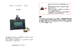
![AISER [USER MANUAL OF AISER] - Internet Banking](http://vs1.manualzilla.com/store/data/005712358_1-d8e4e34a51ac40b22276b6e3d3c9bbc0-150x150.png)