1
7
4,197,427
The concentrator 8 system further provides for sub
scriber line or system trunk lockout. If the PCC 12, 22
8
processor with the use of the S0, S1, S2 and SYNC
cannot establish data link communication on a given
output control lines generated by the INTEL 8008. In
the present embodiment S0, S1, S2 and SYNC are de
trunk, or if maintenance personnel have manually input
coded in the state decoder 212 to create in a conven
ted to the PCC 12, 22 that a trunk be taken out of ser
tional manner, many of the microprocessor 60 control
signals. These include the control signals defined as the
vice, then the trunk is locked out from being used again
by storing these occurrences in the trunk status RAM
76 memory location corresponding to that trunk. If the
PCC 12, 22 cannot establish or maintain data link com
munication on a given trunk then that trunk status word 0
is marked system maintenance out of service (MOS).
Attempts to use this trunk for communication will be
automatically made when all other trunks are busy.
Line lockout can, however, only be done manually by
OE, mitt, ENE, our 1, our 2, and WRITE EN
ABLE (WE) signals.
The various registers in the INTEL 8008 include the
input/output register 202, the arithmetic and logic unit
204, which implements the addition, subtraction and
logic operations called for by the instruction set, and the
accumulator, memory, and program counter registers
206, which among other functions provides temporary
maintenance personnel. Note that no E-coils need to be 5 storage for data being operated on and temporary stor
pulled, as was required in older electromechanical sys
age for program and subroutine addresses.
tems. To manually lockout either a line or a trunk, one
The instruction decode and control unit 208 provides
need only load in the number of the desired line or trunk
the logic for manipulating the registers 202, 206 and the
to be locked out into the PCC 12, 22 via keyboard 110
arithmetic unit 204, based on the type of instructions
along with the lockout command. This lockout ability is 20 read in and decoded by the INTEL 8008. The timing is
needed especially during bad weather conditions, when
regulated by a clock generator 210 that operates from
lines shorting together look to the concentrator 8 sys
an external two-phase clock 86 (see FIG. 2).
tem like a service request that never goes away, thus
It should be noted that in the present embodiment,
the two-phase clock 86 comprises two crystal oscilla
tying up the system as a result. In addition, with the
PCC 12, 22, the concentrator 8 can automatically bring
tors, wherein one is the backup of the other. Therefore,
the malfunctioning line back into service if it detects
if one oscillator has a frequency variation that is more
that the short has gone away. This function is entirely
than minor, circuitry in the two-phase clock 86 unit
control program initiated. Reference is suggested to the
automatically switches in the other oscillator.
System Operation section of this speci?cation for fur
The Watchdog Timer (WDT) 82 is a counter that
ther details regarding the above and regarding the vari
generates timing pulses by counting increments of time
ous other command functions available for externally
de?ned by an input clock pulse from the two-phase
controlling concentrator 8 operation.
clock 86 unit. These timing pulses are used as a micro
A. The Processor Common Control
processor 60 programming aid. The longest time
counted by the WDT 82 is 472 ms. This time interval is
As impliedly stated above, the processor common 35 used as the WDTO signal that generates a microproces
control, both in the COT 10 and in the RT 20, normally
controls virtually every aspect of concentrator 8 system
microprocessor 60 and restart the control program. The
operation. Relay switching commands, trunk status
storage operations, subscriber line scanning, in general
processor 60, so that it never counts up to the 472 ms
sor 60 INTERRUPT, to thus initialize or reinitialize the
WDT 82 is normally periodically reset by the micro
almost all functions are controlled in the present inven 40 time interval, and thus never generates an INTER
tion by these PCC units 12 and 22. Since this aspect of
RUPT. Only when the microprocessor 60 gets stuck,
the concentrator 8 is the most pervasive, the main sub
for example performing an erroneous program task, or
if it has halted, will an INTERRUPT occur. This fea
systems of the PCC 12, 22 will be discussed separately
below.
ture, therefore, automatically frees the system at least
45 temporarily from microprocessor 60 or control pro
(I) The Microprocessor and Watchdog Timer
gram malfunctions. Also, on power start-up, since the
microprocessor 60 has not begun operating, the WDT
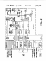
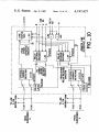
As shown in FIG. 2, the microprocessor 60 is the
82 is never reset but is allowed to count until the 472 ms
main manipulator of data and normally the controller or
has elapsed, creating a WDTO signal and a resultant
supervisor of all aspects of the processor common con
trol 12, 22. All input data passes through the micro
microprocessor 60 INTERRUPT, thereby automati
cally starting up the system without the need for any
processor 60 and all output data, control, and memory
maintenance personnel interaction. More about the
address information is generated through this unit. A
typical type of microprocessor includes the INTEL
8008 8-bit parallel word microprocessor unit, as de
operation of this circuitry is given below in the System
Initialization section of this specification.
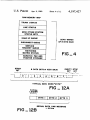
As shown in FIGS. 2 and 3, the state decoder 212
scribed in the INTEL 8008 User’s Manual, Rev. 4, 55
takes the S0, S1, S2 and SYNC outputs of the INTEL
November 1973, with some additional control circuitry
as described below.
8008 along with three lines (AH-A15) from the address
Referring to FIG. 3, the microprocessor 60 communi
register 80 (illustrated in FIG. 2) and the SYNC-diZ line
to generate the above-listed output signals. The OE and
cates over 8 bidirectional lines on the processor bus 90.
TN signals control the input data multiplexer 88, whose
Time multiplexing of the processor bus 90 allows con
function is to input data to the microprocessor 60 either
trol information, addresses and data to be transmitted
from one of the eight input ports 62 or from the ROM
between the processor and external subsystems on this
74 or RAM 76. The IN signal is also used to strobe the
bus. The microprocessor 60 is controlled internally by
input port select 64 to enable data from the desired port
an instruction set of 48 instructions, including data ma
nipulation, binary arithmetic, and jump-to-subroutine 65 to connect through to the input data multiplexer 88
input line. The OUT 1 and OUT 2 signals control
instructions. Microprocessor 60 control is also obtained
whether the latching output ports or the non-latching
via the Watchdog Timer Output (WDTO) line, dis
output ports obtain and output control data from the
cussed below. Other devices may be controlled by the