1
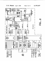
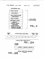
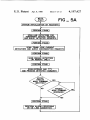
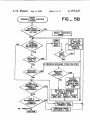
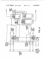
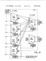
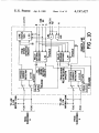
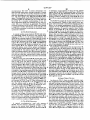
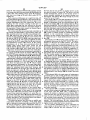
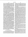
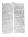
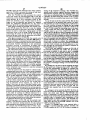
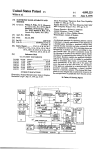
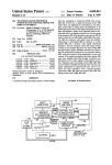
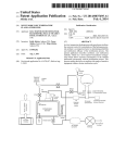
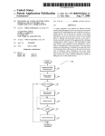
United States Patent ‘[19]
Hutcheson et al.
[54]
DUAL-PROCESSOR LINE CONCENTRATOR
Attorney, Agent, or Firm—Phillips, Moore,
Weissenberger, Lempio & Majestic
[57]
[73] Assignee:
Glaser, Bonham, Tex.; Richard D.
Ross, Reno, Nev.; Wook R. Shim,
Rohnert Park, Calif.
is included at both ends of the concentrator system.
These processors communicate with each other over a
Lynch Communication Systems, Inc.,
randomly chosen idle trunk, thereby negating the need
Reno, Nev.
for a dedicated communication link between the proces
sors. Each processor controls the switching functions at
[21] Appl. No.: 850,592
[22] Filed:
its end of the concentrator, independently monitors and
retains trunk status, subscriber line status and system
Nov. 11, 1977
operational status, and provides system fault detection,
Int. CI.2 ............................................. ,. H04Q 3/60
U.S. Cl. .............................................. .. 179/18 FC
Field of Search .................................. .. 179/18 FC
[56]
diagnosis and recovery including communication to
maintenance personnel of trouble codes based on the
detected fault and its diagnosis. Manual interaction with
References Cited
the system is also enabled at either end of the concentra
tor system via display and input/output units or remote
from both ends.
U.S. PATENT DOCUMENTS
3,592,970
ABSTRACT
A switching system is disclosed for the concentration of
a plurality of telephone lines onto a lesser plurality of
intermediate trunks, wherein an independent processor
both of Reno, all of Nev.; James H.
7/l97l
Capetti et al.
179/18 FC
Primary Examiner--William C. Cooper
c.o.
27 Claims, 14 Drawing Figures
L "E CONCENTRATOR 8
Jk
CENTRAL ?cE TERMINAL
I
— 'FEMOTE TERMINAL _' _ 7d
FI
I0
Lilli
..\
U21:
"
tm
c.o.
I
LINE
I
I
/-~-
TRUNK
---2 sure:
I
"II-Em
no:
I
2 STAGE 0 LINE
I 'I I . FACE
l
I
i
I
'
i
I
| I
I
Il
I
l
II
I I
"'g MATRIX
$W~
i INTER- I ||
I FACE
I
l
I
E
I
I
g
i
I
|
5
I‘
I“
a
I
II
I iI
I
II
I
I
| I
|
I I
I
I
I
I
' |
l
‘
I
1 I
‘
I
I‘I
|
l
I I
L00
I
I
Is
I
___
'
I I
40
PULSER a
con-gem.
I
as
I
‘4
|
ITRANSMITTER
a REcEIvEa
I
I
24
I
so
II I
I 3:35;“
J L ‘°
PROCESSOR
common
coIgaoI.
|
|
' DATA-LINK
TRANSMITTE
I
a REcEIvER
PROCES
commonson
sw. 25cm:
i
Ttnli
amt-LINK
I4
I
I
Is
sus
SCRIBERS
5“
u
I
I
'
l
5‘?
In
INTER_
I I I
8“ REMOTE
..__
rnuux
Tm
I
|
I
_
I I FACE I
l
20
Tm
I I INTER’ I MATRIX
5W-
2
Apr. 8, 1980
SWITCHING SYSTEM
[75] Inventors: Alan G. Hutcheson, Sparks; William
R. Bonham; Calvin H. DeCoursey,
[51]
[52]
[58]
4,197,427
[I ll
[45]
II
I I
23
st"
i
PULSER a
L sw. DECODE
52
I
I
_I
4
US. Patent
Apr. 8, 1980
Sheet4 of 12
4,197,427
RAM MEMORY MAP
TRUNK STATUS
LINE STATUS
MISC. OTHER SYSTEM
STATUS BITS
HANG UP QUEUE
r
DISCONNECT QUEUE
2048 wonos
0'’ 8 BITS EACH
SERVICE
REQUEST QUEUE
SWITCHING
MATRIX STATUS
_4
SCRATCH PAD AND
POINTER STORAGE
Y
TYPICAL DATA WORD "BYTE"
FIG ._ 12A
5-IO IIIS
LEADER
F-’%
BYTE I
BYTE 2
BYTE 3
L
J
Y
SERIAL DATA LINK MESSAGE
FIG -125
US. Patent
Apr. 8, 1980
Sheet 5 of 12
U
[SYSTEM INITIALIZATION OR RECOVERY]
PERFORM PTASK
SCAN LINE DETECTORS FOR
SUBSCRIBER SERVICE REQUEST
AND QUEUE DETECTED REQUESTS
I
PERFORM PTASK
SCAN TRUNK LOOP CURRENT
DETECTORS AND QUEUE DISCONNECTION REQUESTS
PERFORM PTASK
SCAN RINGING DETECTORS
(AT REMOTE ONLY)
I
PERFORM PTASK
SCAN KEYBOAD AND TTY
AND PROCESS DETECTED COMMANDS
ENTER
FRE EZE
MODE COMMAND
INPUTTED ’?
FREEZE
MODE COMMAND
RESCINDED?
PERFORM PTASK
PERFORM ALARM PROCESSING
OR ON-LINE DIAGNOSTICS
I
4,197,427
U.S. Patent
Apr. 8, 1980
Sheet 6 of 12
4,197,427
(PERlODlCST-Ag;
(PTASK) ROUTINE)
IS
WATCHDOG
_
YES
TIMER OVERFLOW
i
B'T 0“?
RESET WATCHDOG
TIMER
I
NO
LOAD
BYTE
UART
No
I
IN NEED
sET FLAG
TO RECEIVE
-—-> INTO
OF MESSAGE
UART DATA
UART
AND SCHEDULE
PROCESSING
RECEIVE
?
TIMEouT.
YEs
YES
YEs
PRocEss MESSAGE FRoM FAR END |
MESSAGE
RECEIVED?
MESSAGE
YES
REPLY
REQUIRED ?
NO
FORMAT
HAS A
XMTR/ RCVR
REQUIRED
REPLY, START
LEADER AND
SET TIMEOUT
TIME
YES
SELECT A MESSAGE
TO SEND ACCORDING
To PRIoRITY OF
No
REQuEsTs, START LEADER
AND sET TIMEouT TIME
sEcDRhDQSETTAsK
o
YES
‘
PERFORM REQ'D I
OCCURRED‘
N0 TIMEouTs
m
PRIMARY TASK "—’lI
.
_
PERFORM REQ'D
SECONDARY TASK
US. Patent
Apr. 8, 1980
4,197,427
Sheet 9 0f 12
TO/FROM I
SUBSCRIBERS
OR 0.0.
l Sf STAGE
I
ORIGINATING
CALLS
L(l)
'-—
TH)
'rglrslcgm
RU
33353035
INTERFACE
42.52
[6,26
-— I118)
'2-
PULSER a
sw oecoos
42 52
I
.
'
SIO
I
I
1
8
7
I
/
'
42,52
2
\\
I6
I
l
'6" 8
é a
: LINES
"ATR'X
sw
:'
SIO
1*
'“ As
I‘ -—— [119)
ISxB
: SW
=
lI
a| _—
I MATR'X
SIO
/
5W DEQODE
42, 52
42,52
2
PULSER 8|
SW DECODE
42, 52
INTERFACE
T(l6)
l
PULSE" 8'
sw oecom»:
D— - N
‘2.45:?
I
I
PULSER a
2O
I
a
NES
i
l
I
|
_ __ _ _ _ __ ___l
OUTPUT DATA BUS 98 AND
SW MATRIX SELECT LINES
IN FROM PCC l2,22
1
4, 197,427
2
No. 3,917,908, issued Nov. 4, 1975, a call concentrator
DUAL-PROCESSOR LINE CONCENTRATOR
SWITCHING SYSTEM
BACKGROUND OF THE INVENTION
l. Field of the Invention
The present invention relates generally to telephone
line concentrator switching systems and, more particu
larly, to a concentrator system that includes a processor
at each end of the concentrator for independent control,
at both ends of the concentrator, of switching functions,
error checking, and other functions.
2. Description of the Prior Art
control system.
5
SUMMARY OF THE INVENTION
The present invention consists of two units or termi
nals, a central office terminal and a remote terminal
interconnected by up to 32 trunks. Both terminals con
tain circuitry that function almost identically. The pres
ent invention is designed to switch up to 128 lines onto
a maximum of 32 trunks. Either terminal can accept
incoming requests for service from one of its respective
lines and can create a subscriber signal path through its
own switching network, through an idle trunk, and
?nally through the other terminal‘s switching network.
Since not all subscribers require service at any one
The
two terminals continuously communicate with
time, there is no need to have an equal number of con
each other over a data link, maintained on an idle trunk,
nections between a group of subscribers and a telephone
for the exchanging of the requisite switching status
central oflice. Line concentrators were therefore devel
information and other data. The present invention can
oped to concentrate the number of subscriber lines into
be used on a trunk facility that is made up of physical
a lesser number of trunks which would then be ex 20
cable pairs, carrier trunks, or any other types of trans
tended to the central of?ce. Such an arrangement, how
mission facility, and is electronically transparent to the
ever, was found to be cost-competitive compared to
in-place cable only for relatively simple line concentra
tor switching systems.
subscriber line, introducing no loss or gain. Also, no
the remote end of the concentrator except on the most
expensive of systems, because there was little or no way
of checking whether an error correction made by main
tenance personnel at the remote unit was effective in
The processor common control consists of a micro
processor controlled by a control program stored in a
alterations or modi?cations to the associated central
office subscriber lines is necessary to install the present
In the past, line concentrators tended to be large 25 invention.
electromechanical devices, requiring a high degree of
Each terminal contains ?ve main sections: ( 1) a pro
maintenance, or devices that could operate only using a
cessor common control; (2) data link generation and
subscriber carrier or only if a system were connected to
reception means; (3) a line interface; (4) a trunk inter
a certain type of telephone switching system.
face; and (5) a two-wire stage switching matrix net
Also, maintenance could not be easily performed at
work.
eliminating the problem. This is because system fault or
malfunction indicators were minimal or nonexistent at
the remote unit. In addition, except for the most basic of
maintenance routines, any check-out of a line concen
trator required the interaction of maintenance personnel
to enable the detection of errors and error diagnosis.
Often a system had to be taken out of service before
such error correction tests could be performed. Only
recently have separate monitoring systems been devel
oped to aid in the maintenance of such switching sys
tems. Even these systems, however, have not hereto
fore been inexpensively incorporated as an integral part
of a line concentrator system.
The present invention takes advantage of state-of-the
art microcircuits to create a flexible and powerful line
concentrator system that is cost competitive in compari
son with the alternative of adding further trunk paths,
non-destructive read-only memory (ROM), a random
access memory (RAM), and terminal input/output
means. The RAM is used to store the current status of
lines and trunks, for scratch pad use by the micro
processor, for storage of system errors discovered, and
for storage of certain other indicators periodically
needed by the microprocessor. The microprocessor is
capable of performing arithmetic and logical operations
as well as control and sensing functions. The input/out
put functions of the processor common control are
performed via a plurality of input and output ports and
their related control circuitry under the overall control
of the microprocessor and control program. Finally,
maintenance personnel interaction with a terminal is via
the terminal input/output means of the common control
unit. This means includes a keyboard for inputting of
commands or data requests, a four-digit hexadecimal
display for displaying data and trouble codes, a teletype
interface, and various alarm indicators. Monitoring of
while allowing substantial improvements in operation
the interterminal communications via the data link is
over prior concentrator devices to be made. The pres
also possible at a distance from the concentrator system,
ent invention allows full system check-out to be made,
as will be described herein.
at either the central of?ce unit or the remote unit, of any
The line and trunk interface units provide detection
system faults or errors which have been automatically
of subscriber service requests, trunk idle status, data link
discovered by the unit. Full control over system opera
switching from one idle trunk to the next, etc. A trans
tion and access to trouble codes and systems status is
mitter/receiver in each terminal allows the processor
available to maintenance personnel at both the central 60 common control units to converse with each other via a
office terminal and at the remote terminal. The inven
data link path on an idle trunk. The data is transmitted
tion also provides other unique features in the areas of
as a serial bit string, and at a slow enough bit rate such
real-time maintenance of trunks and lines, intercommu
that no special high speed transmission characteristics
nication between the central office terminal and remote
are needed for the host trunk.
terminal over idle trunks, and other advantages as de 65
Accordingly, it is a principal object of the present
scribed herein. Patents of general interest include U.S.
invention to provide a line concentrator system that
Pat. No. 3,980,839 issued Sept. 14, 1976, a maintenance
monitor for telephone switching systems, and U.S. Pat.
takes advantage of the inherent ?exibility, low cost, and
expanded system control of co~equally operating, mi
3
4,197,427
croprocessor controlled, terminals at both ends of the
concentrator.
Another object of the present invention is to provide
a system that takes advantage of the compactness and
hardware simpli?cations inherently made possibly by
state-of-the-art microcircuits.
Yet another object of the present invention is to pro
vide for data link communication between concentrator
terminals over an idle trunk, thus negating the need for
a dedicated trunk useable only for such communication.
Note that in the present invention if all trunks are busy,
there is no need for data link communication.
A further object of the present invention is to enable
performance of real-time system maintenance checking
from either terminal, both automatically by the system
and via maintenance personnel commands, without
requiring system shutdown. Also enabled is the read
control program executed by the microprocessor unit
of FIG. 2;
FIG. 6 is a schematic of one of the trunk interface
units shown in FIG. 1, and related circuits;
FIG. 7 illustrates an embodiment of the transmitter/
receiver and data link generator shown in FIG. 1;
FIG. 8 is a detailed block diagram of a two-stage
switching matrix shown in FIG. 1;
FIG. 9 illustrates the circuitry of one of the switch
matrices of FIG. 8;
FIG. 10 is a detailed block diagram of the remote
terminal line interface unit shown in FIG. 1;
FIG. 11 is a detailed block diagram of the central
office terminal line interface unit shown in FIG. 1; and
FIGS. 12A and B illustrate the timing and format of
a typical data link message.
DESCRIPTION OF THE PREFERRED
EMBODIMENT
out at either terminal of system errors discovered in
cluding error diagnosis, such that maintenance person
nel are directed to speci?c repairs to be performed.
Still another object of the present invention is to take
advantage of the processor common control in each
terminal for the independent retention in both terminal
of line and trunk status, to enable the retention of system
operational status by at least one terminal in case of
power failure at the other end.
A still further object of the present invention is to
insure that a trunk is operational before a path is
switched through it, by periodically using this intended
trunk as the temporary processor common control data
link, for intercommunication between the terminals. If
either of the process common control units find the
trunk to be inoperative, neither will switch in a sub
scriber over this path but will instead search for a new
idle trunk that is operational.
Yet still another object of the present invention is to
provide for each processor common control to have the
ability to automatically discover, store, and display
system operational faults or errors, to lock out the lines
or trunks corresponding to these errors if possible until
repaired, and to tell maintenance personnel how to
repair the detected errors, to thereby minimize mainte
nance personnel training required for maintaining
proper system operation and to enable maintenance
personnel interaction with the system to be minimal
when such interaction is required.
Yet another object of the present invention is to pro
vide automatic traffic usage analysis for determination
of heavy subscriber usage on a particular line, group of
lines, etc. Such analysis enables the even distribution of
high usage and low usage subscribers over all line
groups.
4
FIGS. 5A and B illustrate a flow diagram of the
1. GENERAL
The line concentrator switching system 8 is illus
trated in block diagram form in FIG. I. The concentra
tor 8 is composed of a central office terminal (COT) l0
and a remote terminal (RT) 20. A service request origi
nating either from the central office (CO) 2 or from a
remote subscriber 4 is processed in virtually the same
way by either terminal except for minor variations to be
described herein. Therefore, referring to the remote
terminal‘s operation as an example, the processor com
mon control (PCC) 22 regularly scans the subscriber
lines S(1)—S(N) connected to RT 20 for detection of the
next concentrator 8 system service request. Circuitry in
a line interface 28, accessed and controlled by the PCC
22, enables this process.
During the scanning process, a data link between the
remote terminal PCC 22 and the central office terminal
PCC 12 is maintained if an idle trunk exists. If no idle
trunks are available, the PCC‘s must wait until a trunk
goes idle before interterminal communication over a
data link can be reestablished. Note that a data link path
is not needed by the concentrator 8 if all trunks are
busy, since no new switching can occur until a trunk
goes idle.
The content of data link communication, if no re
quests for service are detected, consists usually of just
the comparing by each terminal of the other terminal‘s
status. Note that the time interval between the sending
of a message and the reception back of a reply and the
times available between segments of messages are when
the terminal does its scanning for new service requests
and any other routines needing to be performed, so that
it is ready to respond when the next message time oc
BRIEF DESCRIPTION OF THE DRAWINGS
These and other objects and advantages of the pres
ent invention will become more apparent upon refer
ence to the following description and the accompany
curs.
ing drawings in which:
is assuming a data link already has been established. If
FIG. 1 illustrates in general block diagram form a line
concentrator system according to the present invention;
the other terminal has not received an error free mes
FIG. 2 is a more detailed block diagram of the pro
cessor common control unit shown in FIG. 1;
FIG. 3 illustrates an embodiment of the microproces
sor unit shown in FIG. 2;
FIG. 4 is a block diagram depicting memory alloca
tions of the RAM memory shown in FIG. 2;
When a service request is detected by the PCC 22 as
described above, it sends to the other terminal this fact,
and including the selected switch path and trunk chosen
by the PCC 22 to complete the requested call path. This
sage, a request that the message be retransmitted is sent
back. If the message is error free, both of the PCC‘s
switch off of the trunk used as the data link and enable
the line requesting service to be switched onto this
trunk or onto another chosen trunk depending on traffic
load parameters. Both terminals then switch to the next
idle trunk to attempt the reestablishment of the data link
5
4, 197,427
on this new trunk. Stored trunk status tables in each
PCC 12, 22 are what the terminals use to ?nd which
trunks are idle and which are presently in use. If more
than one idle trunk exists, an algorithm is performed by
each terminal to choose which of the available trunks
will be used to reestablish the data link.
The data link switching circuits described above and
trunk status indicators comprise the trunk interface 26
in the RT 20 and the trunk interface 16 in the COT 1D.
Ringing detectors 34 are also provided at the RT 20 to 0
verify a ringing signal from the COT 10. The switching
of a line requesting service to an available trunk is per
6
takes 40 milliseconds (ms) to complete. Further details
on the operation of the XMTR/RCVR 40, 50 is pro
vided in the Data Link section of the speci?cation here
inbelow.
As illustrated in FIG. 2, interaction by maintenance
personnel with the line concentrator system is via a
4-digit hexadecimal display 106, a front panel keyboard
110, a teletype interface 108, and various alarm circuits
in an alarm and power unit 104 which exist both at the
COT 10 and at the RT 20. Maintenance of the concen
trator system is made easy by diagnostic routining, via
programs stored in the ROM 74, and by system mainte
nance monitoring, via the maintenance monitor 100,
formed in a two-stage switching matrix 24 in the RT 20
both of which are periodically automatically performed
and in an identical switching matrix 14 in the COT 10.
Lastly, battery means 30 are also included at the RT 20 5 by each PCC and which may also be requested to be
to provide auxiliary power automatically switched in
performed by maintenance personnel. Any errors dis
during power failure. Such failures are more likely at a
covered as a result of this process are analyzed and
remote terminal since they tend to be located in rural
and developing areas. Battery means 30 is rated to pro
vide eight hours to emergency power.
diagnosed by the PCC, such that maintenance personnel
FIG. 2 illustrates, in block diagram form, the proces
sis of the errors, is stored in trouble number codes to
will be directed to predetermined corrective proce
dures. The errors detected, including the PCC‘s diagno
sor common control unit of both terminals, i.e. PCC 12
and 22. The processor common control comprises a
await readout by maintenance personnel. Operational
microprocessor unit 60 controlled by a control cycle
program stored in a read only memory (ROM) 74. A
above routines are also stored in trouble number format.
Note that these maintenance routines are designed to
operate so that they do not interfere with normal con
errors detected by the PCC 12, 22 independently of the
ROM is used because the control program is the perma
centrator 8 system operation.
nent system controller of the terminal. No change in the
Initialization of stored system status during system
control program is desired or normally possible once
start up, and reinitialization of stored system status, also
the ROM has been modi?ed to re?ect the steps of the
control program therein. The PCC also includes a ran 30 involves special provisions. When the concentrator 8 is
initially turned on, both terminals establish data link
dom access memory (RAM) 76 which is used to store
communication on an arbitrary trunk. If data link com
the current status of lines and trunks in the concentrator
munication is successfully established on this ?rst trunk,
8 system and to store other subscriber service data. The
or if after an arbitrary number of attempts, communica
RAM 76 is also used for the storage of any system oper
tion is not established over this trunk, each PCC 12, 22
ating errors detected and for the storage of trunk ser
records this fact in its trunk status table and then contin
vice requests, if more than one request is pending at a
ues on to a next trunk to attempt communication on this
given time. Access to the ROM 74 and the RAM 76 is
new trunk. This procedure is repeated until all trunks
via a bidirectional processor bus 90 for the outputting of
have been checked and their operational status re
data to the RAM memory and via an input data multi
plexer 88 for the inputting of data to the microprocessor 40 corded in trunk status tables for future reference. These
tables are stored in each terminal‘s respective RAM.
60 from the RAM and ROM memory units. An address
With the data link established on the last trunk checked
register 80 loaded by the microprocessor 60 via the
by the PCC 12, 22, the PCC’s 12, 22 begin their respec
processor bus 90 de?nes what storage location in mem
tive scans for subscriber requests for service, while
ory 74, 76 is accessed by the microprocessor 60.
The PCC 12, 22 also contains various input and out 45 continuing to communicate, one with the other, as was
brie?y described above.
put ports 62, 66 and 70 and associated port selection
If either terminal loses its line and trunk status infor»
registers 64, 68 and 72 for the outputting of data and
control signals and for the inputting of data and the
monitoring of control signals, as will be described in
more detail herein.
Referring again to FIG. 1, before data from a PCC
can be put out on a trunk for transmission to the other
terminal’s PCC or received from that other terminal, it
must pass through the data link transmitter/receiver
(XMTR/RCVR) 40 in the COT 10 and the data link
transmitter/receiver (XMTR/RCVR) 50 in the RT 20.
These units are needed to slow down the data, because
the trunks are not designed with the ability to transmit
information at the speed that the PCC operates at. Only
voice grade signals can be transmitted thereon. The
data link data is formatted as a serial bit string which is
transmitted via an FSK (frequency shift keying) coding
system. The XMTR/RCVR 40, 50 accepts a plurality
of parallel digital 8-bit words from the PCC 12, 22 and
mation due to a power failure, subscriber lines that are
presently coupled through the concentrator 8 system
50 are able to continue to be so, since magnetically latching
relays are used in the concentrator switching matrix 14,
24. These relays do not require any power to retain their
present state. When power is returned to the terminal
that has lost its data, it indicates to the other terminal
that is has resumed operation and that it is in need of
system status updating. With the other terminal storing
a duplication system status, knowledge of the position
of each switch in the switch matrix 14, 24 in both termi
nals is retained. Thus the terminal that has not lost its
power has the ability to transmit this system status data
over the data link to the requesting terminal, to thereby
automatically bring this terminal back into an opera
tional state.
If both terminals lose power, system status is irre
converts these words into a serial data bit string. The 65 trievably lost, i.e., neither terminal knows which sub
scriber line is switched onto a given trunk. Therefore
XMTR/RCVR 40, 50 further performs the opposite
both terminals will clear down their line and trunk
function for messages received by it from the other
relays to insure starting at a known state.
terminal. In the present embodiment, each message
7
4,197,427
The concentrator 8 system further provides for sub
scriber line or system trunk lockout. If the PCC 12, 22
8
processor with the use of the S0, S1, S2 and SYNC
cannot establish data link communication on a given
output control lines generated by the INTEL 8008. In
the present embodiment S0, S1, S2 and SYNC are de
trunk, or if maintenance personnel have manually input
coded in the state decoder 212 to create in a conven
ted to the PCC 12, 22 that a trunk be taken out of ser
tional manner, many of the microprocessor 60 control
signals. These include the control signals defined as the
vice, then the trunk is locked out from being used again
by storing these occurrences in the trunk status RAM
76 memory location corresponding to that trunk. If the
PCC 12, 22 cannot establish or maintain data link com
munication on a given trunk then that trunk status word 0
is marked system maintenance out of service (MOS).
Attempts to use this trunk for communication will be
automatically made when all other trunks are busy.
Line lockout can, however, only be done manually by
OE, mitt, ENE, our 1, our 2, and WRITE EN
ABLE (WE) signals.
The various registers in the INTEL 8008 include the
input/output register 202, the arithmetic and logic unit
204, which implements the addition, subtraction and
logic operations called for by the instruction set, and the
accumulator, memory, and program counter registers
206, which among other functions provides temporary
maintenance personnel. Note that no E-coils need to be 5 storage for data being operated on and temporary stor
pulled, as was required in older electromechanical sys
age for program and subroutine addresses.
tems. To manually lockout either a line or a trunk, one
The instruction decode and control unit 208 provides
need only load in the number of the desired line or trunk
the logic for manipulating the registers 202, 206 and the
to be locked out into the PCC 12, 22 via keyboard 110
arithmetic unit 204, based on the type of instructions
along with the lockout command. This lockout ability is 20 read in and decoded by the INTEL 8008. The timing is
needed especially during bad weather conditions, when
regulated by a clock generator 210 that operates from
lines shorting together look to the concentrator 8 sys
an external two-phase clock 86 (see FIG. 2).
tem like a service request that never goes away, thus
It should be noted that in the present embodiment,
the two-phase clock 86 comprises two crystal oscilla
tying up the system as a result. In addition, with the
PCC 12, 22, the concentrator 8 can automatically bring
tors, wherein one is the backup of the other. Therefore,
the malfunctioning line back into service if it detects
if one oscillator has a frequency variation that is more
that the short has gone away. This function is entirely
than minor, circuitry in the two-phase clock 86 unit
control program initiated. Reference is suggested to the
automatically switches in the other oscillator.
System Operation section of this speci?cation for fur
The Watchdog Timer (WDT) 82 is a counter that
ther details regarding the above and regarding the vari
generates timing pulses by counting increments of time
ous other command functions available for externally
de?ned by an input clock pulse from the two-phase
controlling concentrator 8 operation.
clock 86 unit. These timing pulses are used as a micro
A. The Processor Common Control
processor 60 programming aid. The longest time
counted by the WDT 82 is 472 ms. This time interval is
As impliedly stated above, the processor common 35 used as the WDTO signal that generates a microproces
control, both in the COT 10 and in the RT 20, normally
controls virtually every aspect of concentrator 8 system
microprocessor 60 and restart the control program. The
operation. Relay switching commands, trunk status
storage operations, subscriber line scanning, in general
processor 60, so that it never counts up to the 472 ms
sor 60 INTERRUPT, to thus initialize or reinitialize the
WDT 82 is normally periodically reset by the micro
almost all functions are controlled in the present inven 40 time interval, and thus never generates an INTER
tion by these PCC units 12 and 22. Since this aspect of
RUPT. Only when the microprocessor 60 gets stuck,
the concentrator 8 is the most pervasive, the main sub
for example performing an erroneous program task, or
if it has halted, will an INTERRUPT occur. This fea
systems of the PCC 12, 22 will be discussed separately
below.
ture, therefore, automatically frees the system at least
45 temporarily from microprocessor 60 or control pro
(I) The Microprocessor and Watchdog Timer
gram malfunctions. Also, on power start-up, since the
microprocessor 60 has not begun operating, the WDT
As shown in FIG. 2, the microprocessor 60 is the
82 is never reset but is allowed to count until the 472 ms
main manipulator of data and normally the controller or
has elapsed, creating a WDTO signal and a resultant
supervisor of all aspects of the processor common con
trol 12, 22. All input data passes through the micro
microprocessor 60 INTERRUPT, thereby automati
cally starting up the system without the need for any
processor 60 and all output data, control, and memory
maintenance personnel interaction. More about the
address information is generated through this unit. A
typical type of microprocessor includes the INTEL
8008 8-bit parallel word microprocessor unit, as de
operation of this circuitry is given below in the System
Initialization section of this specification.
As shown in FIGS. 2 and 3, the state decoder 212
scribed in the INTEL 8008 User’s Manual, Rev. 4, 55
takes the S0, S1, S2 and SYNC outputs of the INTEL
November 1973, with some additional control circuitry
as described below.
8008 along with three lines (AH-A15) from the address
Referring to FIG. 3, the microprocessor 60 communi
register 80 (illustrated in FIG. 2) and the SYNC-diZ line
to generate the above-listed output signals. The OE and
cates over 8 bidirectional lines on the processor bus 90.
TN signals control the input data multiplexer 88, whose
Time multiplexing of the processor bus 90 allows con
function is to input data to the microprocessor 60 either
trol information, addresses and data to be transmitted
from one of the eight input ports 62 or from the ROM
between the processor and external subsystems on this
74 or RAM 76. The IN signal is also used to strobe the
bus. The microprocessor 60 is controlled internally by
input port select 64 to enable data from the desired port
an instruction set of 48 instructions, including data ma
nipulation, binary arithmetic, and jump-to-subroutine 65 to connect through to the input data multiplexer 88
input line. The OUT 1 and OUT 2 signals control
instructions. Microprocessor 60 control is also obtained
whether the latching output ports or the non-latching
via the Watchdog Timer Output (WDTO) line, dis
output ports obtain and output control data from the
cussed below. Other devices may be controlled by the
9
4, 197,427
microprocessor 60. OUT 1 strobes information into
eight latching output ports, having a plurality of output
lines per port and OUT 2 strobes information into the
eight non-latching ports with each port having onlme
line. The final signal is the WRITE ENABLE (WE)
signal. This signal tells the RAM 76 whether the micro
processor wishes to read data out of or load data into
the RAM 76. A detailed understanding of how the
above-described signals are produced by the state de
coder 212 is not necessary to appreciate the present
10
is addressed, except instead of using just the address
register 80, the ROM 74 additionally uses a ROM chip
select register 78. The addressing scheme for both the
ROM 74 and RAM 76 memories is set up so that every
memory location, whether it be in the ROM 74 or the
RAM 76, is uniquely addressable by the microprocessor
60.
The ROM 74 contains all the stored programs for the
line concentrator 8. Details of this control cycle pro
gram will be discussed in the System Operation section
invention. Reference to the INTEL 8008 User’s Manual
is suggested if further information on the speci?c con
below. In the present embodiment, the ROM 74 has a
capacity of over 14,000 words. It is further designed to
trol circuitry necessary to provide the described signal
operations is desired.
enable expansion of memory capacity when needed.
(2) The RAM Subsystem
A typical random access memory (RAM) and mem
ory addressing scheme is shown in the system block
diagram of FIG. 2. In the present embodiment, the
RAM 76 has a storage capacity of 2048 eight-bit words.
Memory addresses from the microprocessor 60 are cou
pled by the processor bus 90 to a sixteen-bit address
Stored in the ROM 74 is the concentrator 8 system
15 control program for use by and control of the micro
processor 60. The advantages of ROM controlled sys
tems is that once data or instructions are stored in the
ROM, the information cannot be affected by system
power failure or processor re-programming, whereas
information in a RAM is alterable in these ways. Note
that ROM’s can be initially programmed only by special
devices at the factory, and although some ROM’s have
the capability of being re-programmed, this also can
register 80. Control signals CLR, Eli, and E'r? from
only be accomplished by special devices which are not
the microprocessor 60, strobe an address into the ad
dress register 80 as two eight-bit bytes to create the 25 a part of the present invention.
The ROM 74, if addressed by the microprocessor 60,
sixteen-bit address word. In the present embodiment,
outputs data onto the same memory bus 92 as does the
only 12 of these sixteen address bits are used in address
RAM 76. This data is coupled to the processor 60 via
ing the RAM 76. The address register 80 is required to
the input data multiplexer 88 and processor bus 90. The
retain the address desired, since the processor bus 90 is
also used in a later part of the microprocessor 60 mem 30 addressing scheme for the ROM 74 is slightly different
from that of the RAM 76, in that the address register 80
ory cycle as a data bus, wherein data is either received
only feeds the ?rst eight bits of address directly to the
by the microprocessor 60 or sent out from it to be stored
ROM 76 for word selection, while four additional ad
in the RAM 76.
dress bits (e.g. A8-All) are coupled to the ROM chip
During a read cycle, the RAM 76 outputs data to the
microprocessor 60 on the memory data bus 92. During 35 select register 78. In the present embodiment, the regis
ter 78 comprises a plurality of chip select registers, one
such a read cycle, the data is coupled to the micro
each on each memory board containing ROM chips.
processor 60 from the memory data bus 92 through an
The register 78 functions to selectively enable the ad
input multiplexer 88, which is used to give the micro
dressing of a given ROM chip based on the state of
processor 60 the choice of inputting either RAM 76 or
ROM 74 memory information or data from one of the 40 address bits A8-A13. Each ROM chip presently con
tains 256 eight-bit words, so that address bits A¢—A7
input ports 62. The output from the input multiplexer 88
are used to select a specific word location on the ROM
is coupled to the microprocessor 60 by the bidirectional
chip selected by the register 78. It is within the scope of
processor bus 90. Data is inputted to the RAM 76 for
the present invention to incorporate ROM’s of higher
storage directly from the microprocessor 60 by means
of the processor bus 90. As mentioned above, the RAM 45 bit density as they become available, e.g. ROMs having
2024 eight-bit words.
76 is told whether or not the microprocessor 60 wishes
to write data into the RAM 76 or read data from the
RAM 76 by means of the WRITE ENABLE (W—E) line,
as illustrated in FIGS. 2 and 3. When information is to
be read from the RAM 76 to the micgprocessor 60,
only the address need be given, the WE line is not
strobed. Writing informatirmnto the RAM 76, how
ever, does require that the WE line be strobed.
As shown in FIG. 4, the RAM 76 is organized into
(4) Input/Output Devices
As shown in FIG. 2, there are eight latchable regis
ters of eight bits each that comprise the output ports 66,
and eight strobing output ports 70 of one bit each. These
output ports 66, 70 communicate control functions and
data to the respective devices, corresponding to a given
port, that the microprocessor 60 wishes to access. The
different sub-blocks, including blocks of storage space 55 ports 66, 70 connect to subsystems both within the PCC
12, 22 and external to it. The means for choosing which
for trunk and switching matrix status, a scratch pad for
port passes information to its respective subsystem com
temporary storage of numbers being operated on, a
prises two output port select units 68, 72. The port
queue for the storage of detected service requests that
select 68 selects one of the eight latching output ports 66
have not yet been switched through, and various pro
for information transfer, and the port select 72 selects
gram pointers for enabling the microprocessor 60 to
one of the eight strobing ports 70 for information trans
return to routines that have been temporarily stopped in
fer. Each port select unit 66, 72 decodes three input
order to perform routines of higher priority.
lines (A9-All) from the address/data bus 92 into eight
(3) The ROM Subsystem
output lines for individual selection of one of the eight
A typical, non-destructive, read only memory 65 output ports. The OUT 1 and OUT 2 signals, originat
ing from the microprocessor 60 also input to the port
(ROM) 74 and memory addressing scheme is also
select units. Signal OUT 1 enables operation of port
shown in the system block diagram of FIG. 2. The
select 68, and signal OUT 2 enables operation of port
ROM 74 is addressed in the same way that the RAM 76
11
4,197,427
12
select 72. The output port 66 latchablc registers remain
62. Note that as seen in FIG. 1, backup power can be
in a chosen state until microprocessor 60 modi?cation at
provided by means of battery 30. The power unit 104
would automatically switch in this backup power if
a later time. The strobing output ports 70, however,
only stay on as long as the port select pulse OUT 2
power normally available at the remote terminal was
remains on.
interrupted. The battery 30 is large enough to provide
Each output port 66 passes up to eight bits (Adi-A7)
from the address/data bus 96 out to the selected device.
Each output port 70 only passes one bit per port. In the
power for up to 8 hours.
The display 106 is a four-digit hexadecimal read-out
with associated drive circuitry. Information to be dis
present embodiment, since the output port 70 is non
played is transmitted from the microprocessor 60 di
latching, the only circuitry existing in this unit is a
buffer gate connecting the line selected by the port
rectly to the display 106 via the address/data bus 96 on
select 72 and the selected device. For further details on
indicate the numeral or letter desired and the next three
the operation of these units, consult the System Opera
tion section of this speci?cation.
bits (A4-A6) selects which of the four digits will obtain
the new data. A control signal from the output port 70
enables the display 106 to accept this data. The display
106 is used to con?rm receipt of commands manually
inputted to the concentrator terminal. The micro
lines Arb through A6. The low order four bits (Acb-A3)
The various units that are accessed and controlled via
the output ports 66 include: a switch matrix select unit
102, an alarm and power unit 104, and a teletype inter
face 108, which are units within the PCC 12, 22; and
include the line interface 18, 28, the trunk interface 16,
26, and the XMTR/RCVR 40,50, which are units exter
nal to the PCC 12, 22. The output port 66 also includes
one port for the PCC output data bus 98, and one port
for maintenance monitor 100 control. In the present
embodiment, all of these above-mentioned ports 66
mation is in the form of trouble numbers. The trouble
number is coded by the microprocessor 60 to allow
contain eight output signal paths except for the
XMTR/RCVR 40, 50 which needs only six, the tele
ble number dictionary for an explanation of what type
type interface 108 which only needs three, and the
maintenance monitor 100 which also only needs three.
The various units that are accessed and controlled by
the output ports 70 include the display 106 (one line),
the WDT 82 reset (one line), the teletype interface 108
(two lines), and the XMTR/RCVR 40, 50 (four lines).
The PCC 12, 22 also contains eight input ports 62 of
eight bits each. These input ports 62 receive information
processor can also output system status and other data
or request the user to input additional data via the dis
play 106.
The display unit 106 is further used to display error
information discovered by the PCC 12, 22. This infor
maintenance personnel to look up the number in a trou
of error has been detected and what the suggested re
pair procedure is. The microprocessor 60 and control
program perform the system error analysis that makes
this possible (see the System Operation section below).
The ?rst trouble number of a detected error automati
cally appears on the display 106. Subsequent trouble
numbers are stored in the RAM 76 for later readout by
maintenance personnel.
As mentioned above, the display 106 also is capable
from both internal PCC 12, 22 subsystems and from
of displaying other data. Such data includes subscriber
subsystems external to it. The output bus of the input
port 62 is the input port data bus 94 which couples
line trat'?c information, or the contents of speci?c mem
ory words in the RAM 76. Maintenance personnel can
selected inputted information to the input data multi
even enable the display to continuously read-out a word
plexer 88, and thereby to the microprocessor 60. The
means for selecting which input port receives and 40 from memory to enable the monitoring of data stored at
that memory location as it changes. Maintenance per»
passes information to the input port data bus 94 com
sonnel can control what is displayed by means of the
prises an input port select 64. This unit operates simi
keyboard 110 or the teletype 108 as further described
larly to the output port select 68 in that it decodes three
below.
input lines (A9-A11) from the address/data bus 96 into
eight output lines for individual input port selection. 45 The keyboard 110 is the main means of maintenance
personnel input to and control of the line concentrator
The various units that input data via the input ports
8 system. Using the keyboard 110, maintenance person
62 include: the keyboard 110, the maintenance monitor
nel can request that system diagnostics be performed,
100, and the teletype interface 108, which again are
request that other special command routines be per
internal to the PCC 12, 22; and trunk interface 16, 26
status, line interface 18, 28 status, an input data bus, an
output data bus (fed back from an output port 66), and
XMTR/RCVR 40, 50 status and data, all of which
originate from sources external to the PCC 12, 22.
Turning now to the operation of the various input
/output subsystems mentioned as being internal to the
PCC 12, 22, reference is ?rst made to the switching
matrix select 102. This unit merely takes the eight out
put port lines selectively inputted to it, under the con
trol of the output port select 68, and decodes these into
32 lines for switching matrix 14, 24 selection, as will be
further described in the Switching Matrix and Matrix
Decode section of this speci?cation.
The alarm and power unit 104 turns on audible and
formed by the microprocessor 60, e.g., request a traf?c
analysis routine, request system status information, tell
the PCC 12, 22 to lockout a line if it is malfunctioning,
force the switching of a particular line to trunk path,
and other functions.
The keyboard 110 is a standard telephone push-but
tom unit whose outputs are digitized and coupled to one
of the input ports 62. Each time a push-button is
pressed, the number is displayed on the display 106 to
verify that the PCC 12, 22 has correctly received that
input. Access to the PCC 12, 22 via the keyboard does
not interrupt system operation. The microprocessor 60
fits in any keyboard request within normal system cycle
periods. The microprocessor 60 only acknowledges
maintenance personnel requests when it is ?nished with
visual alarm indicators, including a front panel alarm
light, to indicate to maintenance personnel that the PCC 65 higher priority subscriber service operations.
12, 22 has detected a system malfunction such as a
power failure. The fact that an alarm has occurred is
then fed back to the microprocessor 60 via an input port
In the present embodiment, once a command has
been entered on the keyboard 110, if an “A" appears on
display 106 it indicates that the command is not ac
13
4,197,427
cepted. A “B” indicates that the system is presently
busy with call processing. A “C” indicates that the
command has been successfully completed. An “E"
indicates that a keyboard 110 data entry is expected.
Finally, an “F” indicates that the system is in a freeze
mode. In the freeze mode, the system will not process
new calls but will continue calls in progress. In this
14
indicating an on-hook state. It may be easier to under
stand these terms if one pictures a subscribers request
for service as his act of taking his phone off of its cradle
or hook in order to make a phone call and the replacing
of the phone back on the hook when the call is finished.
There is, therefore, one off-hook detector for every
subscriber line serviced by the line concentrator 8 re
mote terminal 20.
FIG. 10 illustrates a typical embodiment of an off
mode, certain system modules may be replaced without
requiring system power shut-down.
A teletype interface 108 enables communication to 10
hook detection scheme at a remote terminal 20. In the
and from the PCC 12, 22 to be performed using a stan
present embodiment, there are sixteen lines (A-X) ser
dard teletype unit with attached paper tape reader. This
teletype interface 108 is relatively standard, comprising
mainly a teletype clock and a universal asynchronous
transmitter and receiver (a UART, e.g. a TMS 6011 as
made by Texas Instruments) for input/output to and
from the teletype and control thereof. A teletype con
viced by each line interface 28 board, so that a system
with 64 subscriber lines would contain four such boards.
The use of 16 circuits per line interface board allows for
?exibility in concentrator 8 system subscriber servicing
size. Note that each subscriber line really is two lines,
nector is provided at each concentrator 8 terminal to
the tip and ring lines required for telephone operation in
simplify connection of a teletype thereto. A person
reasonably skilled in the art should be able to construct
such a unit without difficulty.
the present embodiment. The signal that controls which
line interface board 28 is enabled is the 0E(Y) signal,
wherein Y equals ‘the number of interface boards in the
system. This signal is coupled from the PCC 22 to the
line interface 28 boards via an output port 66. Four line
One advantage of having teletype capability in a
concentrator 8 system is that it is easy to remotely hook
up such a teletype unit. That is, it allows the teletype to
interface 28 boards, therefore, require four signals,
operate at a distance from the concentrator 8 system, 25 0131-0134, for individual selection of each board. The
with connection to the concentrator 8, for example,
establishable over an independent telephone line using a
modem. This would enable not only the remote moni
toring of the concentrator 8 system but remote control
as well. For example, multiple concentrator 8 systems
could be monitored at a common location for traffic
studies, etc., or be used to disable a particular subscrib
er’s access to the concentrator 8 system due to that
subscriber’s failure to pay his bill while yet still allowing
microprocessor 60 selects a given OE(Y) signal by load
ing a single bit from address bus 96 into the output port
66 selectively enabled by the port select unit 68. As
mentioned above, one output port is used only for en
abling commands to selected line interface boards.
Referring again to FIG. 10, a relay L4 keeps the
subscriber line hooked up to an off-hook current detec
tor L2 whenever the associated subscriber line is idle.
After an off-hook condition has been detected, relay L4
such a subscriber to receive calls through the concen 35
enables the current detector L2 to be switched out of
trator system. It should be noted that since the micro
processor 60 and control program assert virtually total
control over the PCC 12, 22, the possibilities herein
exempli?ed should not be limiting, except to the extent
that program size is limited in the absolute.
Finally, the concentrator 8 input/output subsystem
includes a maintenance monitor 100. The maintenance
monitor 100 performs the function of wrapping around
the data from all output ports, except for the output data
the subscriber’s loop by the PCC 22. Note that the
subscriber line path is not switched by the line interface
28, i.e. the continuity of this path stays the same. The
relay L4 only allows the off-hook detector to detect the
electrical state of the subscriber line. Note that there is
no automatic on-hook detection for the purpose of re
connecting the off-hook current detector to the sub
scriber line. As a result, the PCC 22, after it has detected
bus 98 which has its own input port 62, and connects 45 by other means that a subscriber’s use of the line has
ended, must access the line interface 28 board to release
this information to one of the input ports 62 for separate
microprocessor 60 checking of all output port 66 states.
The monitor 100 function is performed by means of a
multiplexer within the maintenance monitor 100 having
six eight line input channels and one eight line output.
Note that the lines marked A through D indicate the
various port wrap-arounds that exist. The monitor 100
the corresponding relay L4.
The PCC 22 receives subscriber line off-hook detec
tor status one line at a time. The PCC 22 controls this
status read-out process by means of four output data bus
98 lines (0-3). These four data bus 98 lines are inputted
to a line status multiplexer L30, which uses the state of
multiplexer is controlled by three lines originating in the
the four lines to control which of the sixteen off-hook
microprocessor 60 and fed to the maintenance monitor
detector status lines on a given board is read-out on an
100 on lines “E” via one of the output ports 66.
55 LS(Y) line. No OE(Y) signal is required for line status
With regard to the other control and data lines which
selection. A separate LS line from each line interface
are either coupled from external systems to the PCC 12,
board (LS(1)—LS(4)) connects to one of the PCC 22
22 input ports 62, or outputted from ports 66, 70, these
signal lines will be discussed as each corresponding
system is discussed hereinbelow.
B. The Line Interface
(1) Remote Terminal Line Interface
The remote terminal 20 line interface 28 provides one
input ports 62.
The PCC 22 controls which of the L4 relays on each
board is actuated and released also by means of the
output data bus 98 lines (0—3). These lines are decoded
into sixteen outputs in the L32 and L34. The decision of
whether relay L4 actuation via L32, or relay L4 release
via L34, is accomplished, is controlled by the Fri) and
function, that of off-hook detection. Off-hook is de?ned 65 F1 lines. Recall that each board is selected by a separate
as a subscriber loop closure (request for service) indi
OE(Y) strobe line for relay L4 control. Gates L40 and
cated as a resultant current flow of at least [0 ma. Cur
L42 enable this F4), F1 relay state selection process,
rent detected in the range less than 10 ma is de?ned as
allowing either the Fri) or F1 signal to pass only to the