1
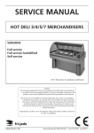
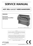
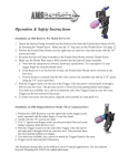
INSTALLATION MANUAL
Bake Basic
MODELS
BB 3-e
BB 3-p
BB 5-e
BB 5-p
Model BB 5-p
- NOTICE This manual is prepared for the use of trained Service Technicians and should
not be used by those not properly qualified. If you have attended a training
for this product, you may be qualified to perform all the procedures in this
manual.
This manual is not intended to be all encompassing. If you have not attended a
training for this product, you should read, in its entirety, the repair procedure
you wish to perform to determine if you have the necessary tools, instruments and skills required to perform the procedure. Procedures for which you
do not have the necessary tools, instruments and skills should be performed
by a trained technician.
Reproduction or other use of this Manual, without the express written consent of
Fri-Jado, is prohibited.
WWW.FRIJADO.COM
Installation Manual Bake Basic form 9123764 rev. 06/2009
TABLE OF CONTENTS
EMPTY PAGE
Page 2
Installation Manual Bake Basic form 9123764 rev. 06/2009
TABLE OF CONTENTS
Index
Index........................................................................................................................................................... 3
General technical data............................................................................................................................... 4
Technical Data . ...................................................................................................................................... 4
Installation procedures.............................................................................................................................. 6
Unpacking and removing the unit from the pallet.............................................................................. 6
Location................................................................................................................................................... 6
Electrical supply...................................................................................................................................... 6
Test run.................................................................................................................................................... 6
Instructions for operators....................................................................................................................... 6
Installation of stand-alone units............................................................................................................... 7
BB 3-p drop in or mounted on skirting bracket .................................................................................. 7
BB 3-p drop in
(with downfalling door ).......................................................................................... 8
BB 5-p drop in or mounted on skirting bracket .................................................................................. 9
Bake Basic “footprint” and air-grids.................................................................................................. 10
Underframes and stacking...................................................................................................................... 11
Assembly instructions underframe 2x9 tray........................................................................................ 11
Assembly instructions underframe 2x5 tray........................................................................................ 13
Stacking of Bake Basic units with kit 3709535................................................................................... 15
Installation examples of units on underframe...................................................................................... 16
BB 3-p on underframe (2x9)................................................................................................................. 16
BB 3-p + 3-P on underframe (2x9) with hood.................................................................................... 17
BB 3-p + 3-P on underframe (2x5) with hood.................................................................................... 18
BB 5-p on underframe (2x9)................................................................................................................. 19
BB 5-p + 5-P on underframe (2x5) with hood.................................................................................... 20
BB 3-p + 5-P on underframe (2x5) with hood..................................................................................... 21
BB 3-p with down faling door on underframe (2x9) . ...................................................................... 22
BB 3-p + 3-P with downfaling door on underframe (2x5) ............................................................... 23
Installation Manual Bake Basic form 9123764 rev. 06/2009
Page 3
GENERAL TECHNICAL DATA
General technical data
This manual covers the Bake Basic series bake-off ovens. The Bake Basic comes in 2 sizes with 3 or 5 baking levels for standard 40x60 cm baking trays. The ovens are also available in stacked versions of 3+3, 3+5 and 5+5.
•
BB 3-e Bake-off oven with 3 levels
•
BB 3-p Bake-off oven with 3 levels, programmable
•
BB 5-e Bake-off oven with 5 levels
•
BB 5-p Bake-off oven with 5 levels, programmable
All of the information, illustrations and specifications contained in this manual are based on the
latest product information available at the time of printing.
Technical Data
STANDARD MODELS
BS 3-e
BB 3-p
BB 5-e
BB 5-p
Power
2840W
2840W
5760W
5760W
230V 1~ 50/60Hz
230V 1~ 50/60Hz
400V 3N~ 50Hz
400V 3N~ 50Hz
Voltage
Max. rated current
13A
13A
9,5
9,5
Fuses needed with power connection400V 3N~50…60Hz ( 3 phases with
neutral)
----------
-----------
3x10A
3x 10A
Fuses needed with power connection
230V 3~50…60Hz (3 Phases without
neutral)
----------
----------
3x 20A
3x 20A
Fuses needed with power connection
230V 1~50…60Hz (1 Phases)
13A
13A
25A
Note: mount
other mains cable
25A
Note: mount
other mains cable
1x EURO Plug
1x UK Plug, 13A
1x EURO Plug
1x UK Plug, 13A
16A 3P+N+E
5 pole CEEFORM
(according to IEC
60309)
16A 3P+N+E
5 pole CEEFORM
(according to IEC
60309)
5x2,5 mm² 2,5mtr
5x2,5 mm² 2,5mtr
92 kg
92 kg
Standard plug from factory
(according to IEC 60309 and CEE-form)
Default cable
Gross weight
Net weight
3x2,5 mm²
2mtr
77 kg
3x2,5 mm²
2mtr
77 kg
63 kg
63 kg
75 kg
75 kg
Hight
460 mm
460 mm
650 mm
650 mm
Width
840 mm
840 mm
840 mm
840 mm
Depth
787 mm
787 mm
787 mm
787 mm
n/a
¾”
n/a
¾”
1 pc of 1”
2 pc of 1”
1 pc of 1”
2 pc of 1”
Waterinlet connection
Fume outlet
Page 4
Installation Manual Bake Basic form 9123764 rev. 06/2009
GENERAL TECHNICAL DATA
Tools
•
Standard set of tools.
•
Metric wrenches, sockets and hex socket key wrenches.
•
Multi-meter and AC current clamp meter.
•
Temperature tester.
•
Insulation value tester (Megger).
•
Field Service Grounding Kit.
•
Puller (part nr. 9191244)
Installation Manual Bake Basic form 9123764 rev. 06/2009
Page 5
INSTALLATION PROCEDURES
Installation procedures
•
Unpacking of the unit.
•
Remove the pallet under the unit with the help of a fork lift or at least 3 people.
•
Put the unit on his location.
•
Check if there is enough free space around the unit (see label.).
•
Check the electrical supply.
•
Check all settings and make a test run with all functions switched on.
•
Give instructions to the operator.
Unpacking and removing the unit from the pallet
Immediately after unpacking the oven, check for possible shipping damage. If the oven is found to be damaged, save the
packaging material (make pictures) and contact the carrier within 15 days of delivery. Remove the pallet under the unit with
the help of a fork lift or at least 3 people.
Location
The oven must be installed on a level and flat surface. The installation location must allow adequate clearances for servicing
and for proper operation.
Make sure that a free airflow for airgrids is ensured. See also chapter “Bake Basic “footprint”and airgrids.
Electrical supply
Prior to installation, test the electrical service to assure that it agrees with the specifications on the machine data plate located on the backpanel. The connecting cable for the unit must be equipped with an approved plug connection. If use is to be
made of a permanent connection, the connecting cable must be connected to a manual on/off switch that is installed near
the unit in a clear visible way.
Test run
Operate the Bake Basic oven at a temperature setting of 250°C, for 30 minutes. Within these 30 minutes the bakestar oven
could release some unpleasant odour as a result of the first heating of some metal parts
Instructions for operators
After installation of the oven, the operator of the unit has to be instructed.
The instruction has to cover the following subjects:
•
Programming and options.
•
Working of the unit.
•
Free space of unit for servicing and for proper operation.
•
Run through the user manual.
•
Cleaning of the unit.
•
How to react for obtaining information or making service calls.
Page 6
Installation Manual Bake Basic form 9123764 rev. 06/2009
PLACING AND CONNECTING
Installation of stand-alone units
BB 3-p drop in or mounted on skirting bracket
205
100
1415
DESCRIPTION OF THE LABELS
7
4 Fume outlet oven, 25mm (all models)
4p Fume outlet oven, 25mm (only p models)
5 Exhaust pipe hood, 180mm
4p
7 Space between the oven and a wall, 100mm
8 Location for wall socket (in conformity with CE)
9 Location for aired tap
“G” ¾ inch (only p models)
946
340
1 Power cable
3 e and p models, 2mtr.
5 e and p models, 2,5 mtr.
2 Watersupply inlet “G”¾”
Tube length 1,5 mtr.
4
47
2
1
7
840
205
5
8
9
777
340
727
4p
4
15
7
460
410
7
8
9
1
2
50
540
50
Mounted on skirting bracket
840
205
5
777
340
727
4p
4
15
7
465
410
7
8
9
1
2
55
798
Installation Manual Bake Basic form 9123764 rev. 06/2009
631
Page 7
PLACING AND CONNECTING
BB 3-p drop in
(with downfalling door )
205
1060
DESCRIPTION OF THE LABELS
7
4 Fume outlet oven, 25mm (all models)
4p Fume outlet oven, 25mm (only p models)
5 Exhaust pipe hood, 180mm
4p
7 Space between the oven and a wall, 100mm
8 Location for wall socket (in conformity with CE)
9 Location for aired tap
“G” ¾ inch (only p models)
946
340
1 Power cable
3 e and p models, 2mtr.
5 e and p models, 2,5 mtr.
2 Watersupply inlet “G”¾”
Tube length 1,5 mtr.
4
47
2
1
7
840
205
5
8
9
777
340
727
4p
4
15
7
460
410
7
8
9
1
2
50
540
50
Mounted on skirting bracket
840
205
5
777
340
727
4p
4
15
7
465
410
7
8
9
1
2
55
798
Page 8
631
Installation Manual Bake Basic form 9123764 rev. 06/2009
PLACING AND CONNECTING
BB 5-p drop in or mounted on skirting bracket
205
100
1420
DESCRIPTION OF THE LABELS
7
4 Fume outlet oven, 25mm (all models)
4p Fume outlet oven, 25mm (only p models)
5 Exhaust pipe hood, 180mm
4p
7 Space between the oven and a wall, 100mm
8 Location for wall socket (in conformity with CE)
9 Location for aired tap
“G” ¾ inch (only p models)
946
340
1 Power cable
3 e and p models, 2mtr.
5 e and p models, 2,5 mtr.
2 Watersupply inlet “G”¾”
Tube length 1,5 mtr.
4
47
2
1
7
840
205
5
8
9
782
340
732
4p
4
20
7
650
7
8
9
600
1
2
50
540
55
Mounted on skirting bracket
840
205
5
782
340
732
4p
4
20
7
655
7
8
9
600
1
2
55
798
Installation Manual Bake Basic form 9123764 rev. 06/2009
636
Page 9
PLACING AND CONNECTING
Bake Basic “footprint” and air-grids
These drawings give a view from the top
“through” the oven to the bottom.
782
The upper drawing is a drop-in unit standing
on its legs.
732
C
The lower drawing gives details from a unit
mounted on a skirting bracket.
750
Top view
D
B
A
Ø75
Ø40 (4x)
58
137
C
840
D
C
540
Airgrids:
Take care of a free airflow towards or from
the airgrids!!
243
A = Airsuction grid cooling fan at bottom side.
B = Airoutlet grid at bottom side.
C = Airoutlet grids at the rear (top).
D = Airoutlet from double door at top side.
Mounted on skirting bracket
782
732
C
D
798
Mounted with 5 screws
max. Ø 6mm
C
840
Top view
D
A
C
58
B
616
96
243
Page 10
Installation Manual Bake Basic form 9123764 rev. 06/2009
PLACING AND CONNECTING
Underframes and stacking
Assembly instructions underframe 2x9 tray
This underframe is suitable for a single BB3, a single BB5 and a double BB3 with standard
door (which is not the “downfalling door”!).
The description below is delivered with the underframe.
Underframe high Bake Basic
H
3706194
3701261
1x
L
3706196
4x
1x
3706197
3706195
2x
1x
3706230
1x
4288325
80x
3706198
3706199
1x
1x
3500148
3706204
3701255
1x
8x
3706202
4x
1x
3706196 (4x)
4288325 (16x)
3706194
3500148 (4x)
A
4288325 (16x)
3706195
Installation Manual Bake Basic form 9123764 rev. 06/2009
B
Page 11
PLACING AND CONNECTING
3706198
! 180
4288325 (16x)
o
3706197
3706197
4288325 (4x)
C
D
! 180
o
3706199
4288325 (9x)
4288325 (5x)
E
F
4288325 (3x)
3701255 (8x)
3706230
H
G
4288325 (4x)
3706202
4288325 (4x)
I
Page 12
J
Installation Manual Bake Basic form 9123764 rev. 06/2009
PLACING AND CONNECTING
Assembly instructions underframe 2x5 tray
This underframe is suitable for a stacked BB3 + BB3, a stacked BB3 + BB5 and a stacked BB5 +
BB5.
The description below is delivered with the underframe.
Underframe middle Bake Basic
H
3706194
3701261
1x
L
3706209
4x
1x
3706211
3706195
2x
1x
3706230
1x
4288325
80x
3706213
3706212
1x
3706210
3701255
1x
1x
3500148
8x
3706202
4x
1x
3706194
3706296 (4x)
3500148 (16x)
3500148 (4x)
4288325 (16x)
A
3706195
B
Installation Manual Bake Basic form 9123764 rev. 06/2009
Page 13
PLACING AND CONNECTING
3706213
4288325 (16x)
3706211 (2x)
4288325 (4x)
C
D
4288325 (9x)
! 180
o
3706212
4288325 (5x)
E
F
3706210
3701255 (8x)
4288325 (3x)
3706230
H
G
4288325(4x)
3706202
4288325 (4x)
I
Page 14
J
Installation Manual Bake Basic form 9123764 rev. 06/2009
PLACING AND CONNECTING
Stacking of Bake Basic units with kit 3709535.
This stacking kit is meant for stacking 2
Bake Basic units.
BB 3+3, BB 3+5, BB 5+5
The kit consists of:
• metal skirting bracket
• 2 pcs of 80 cm silicon tube
(3706202)
(3500608)
Working method:
• Put the first oven on the underframe.
• Remove 5 screws and mount the connection bracket. The position of the air
suction grid is on the right-hand side.
• Put the top oven on the lower one. The
legs will fit in the holes of the bracket.
• Open the back side of both units.
• Nock-out 2 disc-shaped plates in the top
and 2 in the bottom of the top oven.
Note !!: When the lower unit is an -Eversion, only 1 top hole and 1 bottom hole
needs to be nocked-out.
• Remove the short silicon tubes from the
exhaust of the lower unit.
• Put the delivered hoses on the exhaust
of the lower unit and lead them through the top oven like the picture shows.
(The left hose will be situated against
the heating element, which is no problem.)
• Cut the hoses on the desired lenght.
Installation Manual Bake Basic form 9123764 rev. 06/2009
Page 15
PLACING AND CONNECTING
Installation examples of units on underframe
BB 3-p on underframe (2x9)
205
100
1415
4
DESCRIPTION OF THE LABELS
4 Fume outlet oven, 25mm (all models)
4p Fume outlet oven, 25mm (only p models)
5 Exhaust pipe hood, 180mm
4p
958
7
946
340
1 Power cable
3 e and p models, 2mtr.
5 e and p models, 2,5 mtr.
2 Watersupply inlet “G”¾”
Tube length 1,5 mtr.
47
2
1
7 Space between the oven and a wall, 100mm
8 Location for wall socket (in conformity with CE)
9 Location for aired tap
“G” ¾ inch (only p models)
7
8
683
9
695
777
840
205
5
4
340
727
4p
410
8
1470
7
7
9
1
2
55
1005
100
Page 16
Installation Manual Bake Basic form 9123764 rev. 06/2009
PLACING AND CONNECTING
BB 3-p + 3-P on underframe (2x9) with hood
100
1415
DESCRIPTION OF THE LABELS
5
958
7
946
1 Power cable
3 e and p models, 2mtr.
5 e and p models, 2,5 mtr.
2 Watersupply inlet “G”¾”
Tube length 1,5 mtr.
8
9
4 Fume outlet oven, 25mm (all models)
4p Fume outlet oven, 25mm (only p models)
5 Exhaust pipe hood, 180mm
2
1
7 Space between the oven and a wall, 100mm
8 Location for wall socket (in conformity with CE)
9 Location for aired tap
“G” ¾ inch (only p models)
7
683
695
840
5
840
420
5
2135
8
7
410
200
1
2095
1935
7
8
9
1
2
55
7
410
1470
7
8
9
1
2
55
100
1005
Installation Manual Bake Basic form 9123764 rev. 06/2009
Page 17
PLACING AND CONNECTING
BB 3-p + 3-P on underframe (2x5) with hood
100
1415
DESCRIPTION OF THE LABELS
5
958
7
946
1 Power cable
3 e and p models, 2mtr.
5 e and p models, 2,5 mtr.
2 Watersupply inlet “G”¾”
Tube length 1,5 mtr.
4 Fume outlet oven, 25mm (all models)
4p Fume outlet oven, 25mm (only p models)
5 Exhaust pipe hood, 180mm
2
1
7 Space between the oven and a wall, 100mm
8 Location for wall socket (in conformity with CE)
9 Location for aired tap
“G” ¾ inch (only p models)
7
8
683
9
695
840
840
5
420
5
1775
410
8
1735
7
1575
200
1
7
8
9
1
2
55
1110
410
8
9
1
2
55
100
645
Page 18
Installation Manual Bake Basic form 9123764 rev. 06/2009
PLACING AND CONNECTING
BB 5-p on underframe (2x9)
205
100
1420
4
DESCRIPTION OF THE LABELS
1 Power cable
3 e and p models, 2mtr.
5 e and p models, 2,5 mtr.
2 Watersupply inlet “G”¾”
Tube length 1,5 mtr.
4 Fume outlet oven, 25mm (all models)
4p Fume outlet oven, 25mm (only p models)
5 Exhaust pipe hood, 180mm
4p
958
946
340
7
47
2
1
7 Space between the oven and a wall, 100mm
8 Location for wall socket (in conformity with CE)
9 Location for aired tap
“G” ¾ inch (only p models)
7
8
683
9
695
782
840
205
4
340
732
4p
1660
5
600
7
7
8
9
1
2
55
1005
100
Installation Manual Bake Basic form 9123764 rev. 06/2009
Page 19
PLACING AND CONNECTING
BB 5-p + 5-P on underframe (2x5) with hood
100
1420
DESCRIPTION OF THE LABELS
5
958
7
946
1 Power cable
3 e and p models, 2mtr.
5 e and p models, 2,5 mtr.
2 Watersupply inlet “G”¾”
Tube length 1,5 mtr.
4 Fume outlet oven, 25mm (all models)
4p Fume outlet oven, 25mm (only p models)
5 Exhaust pipe hood, 180mm
2
1
7 Space between the oven and a wall, 100mm
8 Location for wall socket (in conformity with CE)
9 Location for aired tap
“G” ¾ inch (only p models)
683
695
840
5
7
8
9
840
420
5
200
2155
8
1
2115
1955
7
600
8
7
9
1
2
55
1300
600
8
9
1
2
55
100
645
Page 20
Installation Manual Bake Basic form 9123764 rev. 06/2009
PLACING AND CONNECTING
BB 3-p + 5-P on underframe (2x5) with hood
100
1420
DESCRIPTION OF THE LABELS
5
958
7
946
1 Power cable
3 e and p models, 2mtr.
5 e and p models, 2,5 mtr.
2 Watersupply inlet “G”¾”
Tube length 1,5 mtr.
8
9
4 Fume outlet oven, 25mm (all models)
4p Fume outlet oven, 25mm (only p models)
5 Exhaust pipe hood, 180mm
2
1
7 Space between the oven and a wall, 100mm
8 Location for wall socket (in conformity with CE)
9 Location for aired tap
“G” ¾ inch (only p models)
7
683
695
840
5
840
420
5
200
1965
8
7
410
1
1925
1765
7
8
9
1
2
55
1300
600
8
9
1
2
55
100
645
Installation Manual Bake Basic form 9123764 rev. 06/2009
Page 21
PLACING AND CONNECTING
BB 3-p with down faling door on underframe (2x9)
205
1060
4
DESCRIPTION OF THE LABELS
4 Fume outlet oven, 25mm (all models)
4p Fume outlet oven, 25mm (only p models)
5 Exhaust pipe hood, 180mm
4p
958
7
946
340
1 Power cable
3 e and p models, 2mtr.
5 e and p models, 2,5 mtr.
2 Watersupply inlet “G”¾”
Tube length 1,5 mtr.
47
2
1
7 Space between the oven and a wall, 100mm
8 Location for wall socket (in conformity with CE)
9 Location for aired tap
“G” ¾ inch (only p models)
7
8
683
9
695
777
840
5
205
4
340
727
4p
410
8
1470
7
7
9
1120
1005
55
1
2
Page 22
Installation Manual Bake Basic form 9123764 rev. 06/2009
PLACING AND CONNECTING
BB 3-p + 3-P with downfaling door on underframe (2x5)
205
1060
4
DESCRIPTION OF THE LABELS
1 Power cable
3 e and p models, 2mtr.
5 e and p models, 2,5 mtr.
2 Watersupply inlet “G”¾”
Tube length 1,5 mtr.
4 Fume outlet oven, 25mm (all models)
4p Fume outlet oven, 25mm (only p models)
5 Exhaust pipe hood, 180mm
4p
958
946
340
7
47
2
1
7 Space between the oven and a wall, 100mm
8 Location for wall socket (in conformity with CE)
9 Location for aired tap
“G” ¾ inch (only p models)
7
8
683
9
695
777
840
205
5
4
340
727
4p
7
410
1575
7
8
9
1
2
1225
55
1110
410
8
9
55
760
1
2
645
Installation Manual Bake Basic form 9123764 rev. 06/2009
Page 23
Fri-Jado B.V. • P.O. Box 560 • 4870 AN • Etten-Leur • The Netherlands • tel +31 76 50 85 400 • fax +31 76 50 85 444 • [email protected] • www.frijado.com