1
R
Appendix A: RocketIO Transceiver Timing Model
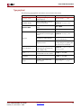
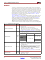
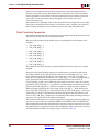
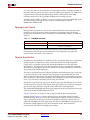
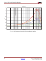
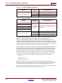
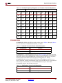
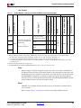
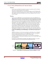
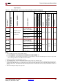
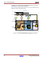
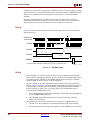
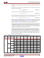
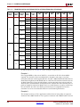
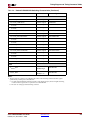
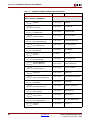
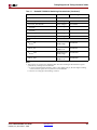
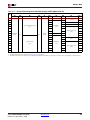
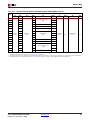
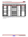
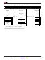
Timing Parameters
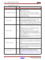
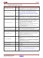
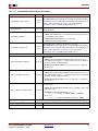
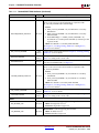
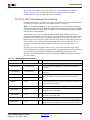
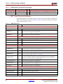
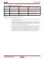
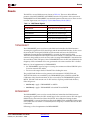
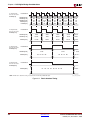
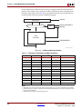
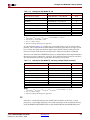
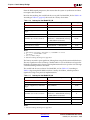
Parameter designations are constructed to reflect the functions they perform, as well as the
I/O signals to which they are synchronous. The following subsections explain the meaning
of each of the basic timing parameter designations used in the tables.
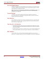
Input Setup/Hold Times Relative to Clock
Basic Format:
ParameterName_SIGNAL
where
ParameterName = T with subscript string defining the timing
relationship
SIGNAL = name of RocketIO signal synchronous to the clock
ParameterName Format:
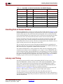
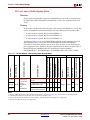
TGxCK = Setup time before clock edge
TGCKx = Hold time after clock edge
where
x = C (Control inputs)
D (Data inputs)
Setup/Hold Time (Examples):
TGCCK _RRST/TGCKC _PLB Setup/hold times of RX Reset input
relative to rising edge of RXUSRCLK2
TGDCK _TDAT/TGCKD _TDAT Setup/hold times of TX Data inputs
relative to rising edge of TXUSRCLK2
Clock to Output Delays
Basic Format:
ParameterName_SIGNAL
where
ParameterName = T with subscript string defining the timing
relationship
SIGNAL = name of RocketIO signal synchronous to the clock
ParameterName Format:
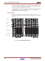
TGCKo = Delay time from clock edge to output
Output Delay Time (Examples):
TGCKO _CHBO Rising edge of RXUSRCLK to Channel Bond outputs
TGCKO_RDAT Rising edge of RXUSRCLK2 to RX Data outputs
TGCKO _TBERR Rising edge of TXUSRCLK2 to TX Buffer Err output
Clock Pulse Width
ParameterName Format:
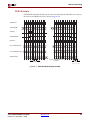
TxPWH = Minimum pulse width, High state
TxPWL = Minimum pulse width, Low state
where
x = REF (REFCLK)
TX (TXUSRCLK)
TX2 (TXUSRCLK2)
RX (RXUSRCLK)
RX2 (RXUSRCLK2)
Pulse Width (Examples):
TTX2PWL Minimum pulse width, TX2 clock, Low state
TREFPWH Minimum pulse width, Reference clock, High state
274
www.xilinx.com
Virtex-4 RocketIO MGT User Guide
UG076 (v4.1) November 2, 2008