1
R
Appendix D
Special Analog Functions
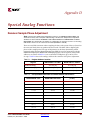
Receiver Sample Phase Adjustment
Note: The Receiver Sample Phase Adjustment function is for ADVANCED USERS ONLY and
should be used only after a complete understanding of the Receiver Sample Phase Adjustment
attributes has been attained. INCORRECT USE COULD RESULT IN UNDESIRABLE SYSTEM
OPERATION. This functionality only applies for configurations in which the receiver is set in analog
CDR mode or the PLL is set to lock to receiver data (RXDIGRX = FALSE).
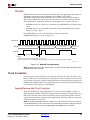
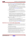
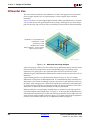
There are serial-link situations where sampling the data at the center of the eye (based on
the recovered clock) does not produce the best results. The MGT allows adjusting the
phase of this sample point. This type of adjustment can be done dynamically, which
requires that the Dynamic Reconfiguration Port (DRP) be used in conjunction with the
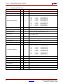
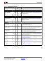
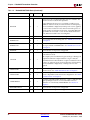
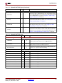
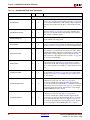
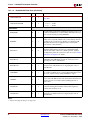
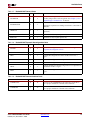
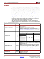
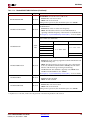
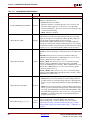
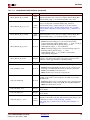
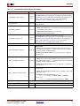
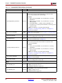
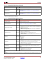
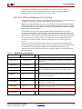
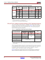
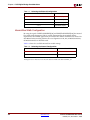
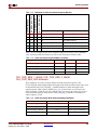
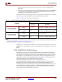
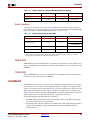
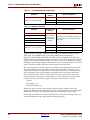
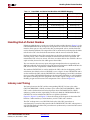
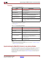
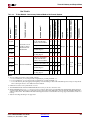
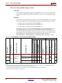
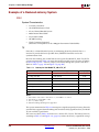
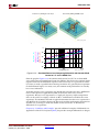
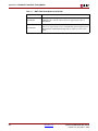
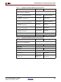
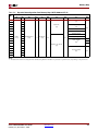
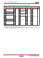
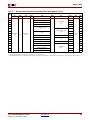
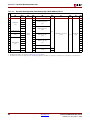
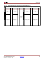
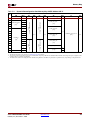
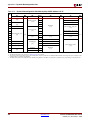
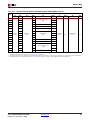
RXSELDACFIX[4:0] and RXSELDACTRAN[4:0] registers. These registers (whose DRP
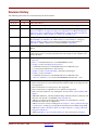
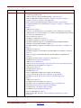
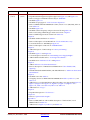
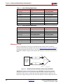
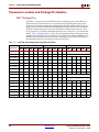
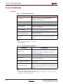
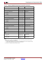
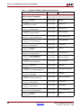
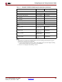
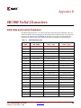
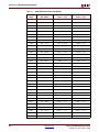
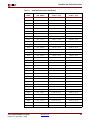
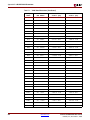
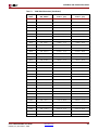
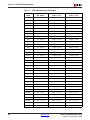
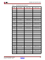
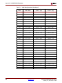
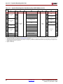
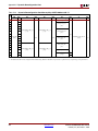
addresses are shown inTable D-1) can co-control the CDR phase up to ±46.9% UI in
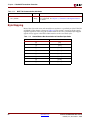
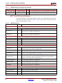
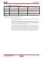
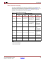
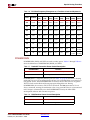
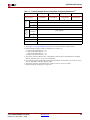
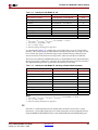
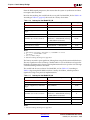
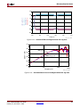
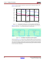
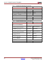
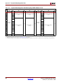
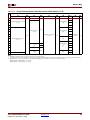
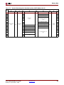
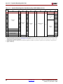
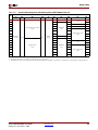
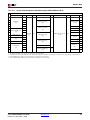
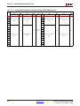
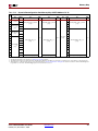
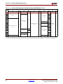
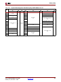
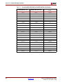
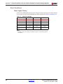
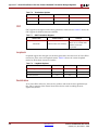
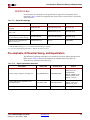
31 steps. Table D-2 shows the settings and how this correlates to UI phase adjustment.
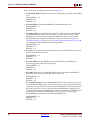
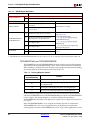
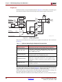
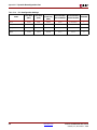
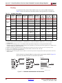
Table D-1:
Register Address Location
Register
MGTA Address and Bits
MGTB Address and Bits
0x56 bit [14]
0x72 bit [14]
RXSELDACFIX[3:0]
0x46 bit [14:11]
0x62 bit [14:11]
RXSELDACTRAN[4:0]
0x46 bit [10:6]
0x62 bit [10:6]
RXSELDACFIX[4]
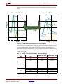
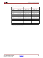
Table D-2:
Example RXSELDACTRAN and RXSELDACFIX Combinations
RXSELDACFIX value
RXSELDACTRAN Value
Phase Adjustment
(in UI%)
11111
00001
–46.875
11110
00010
–43.750
11101
00011
–40.625
11100
00100
–37.500
11011
00101
–34.375
11010
00110
–31.250
11001
00111
–28.125
11000
01000
–25.000
10111
01001
–21.875
10110
01010
–18.750
Virtex-4 RocketIO MGT User Guide
UG076 (v4.1) November 2, 2008
www.xilinx.com
321