1
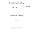
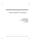
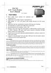
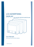
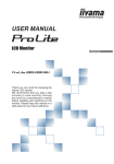
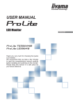
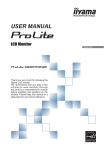
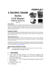
LKM-9358
Eight Input Port
LCD/Keyboard/Mouse
/Speaker Drawer
User Manual
Version 1.0
October 31, 2005
©Copyright
2005
by
IEI
Te c h n o l o g y
Gorp.
All
rights
Reserved.
Copyright Notice
This document and product is copyrighted, October 2005, by IEI Technology Crop. All rights
are reserved. No part of this manual may be reproduced, copied, or translated without prior
notice to IEI Technology Crop.
The information provided in this document is for reference only. We do not assume any
responsibility arising out of the application of the products. This manual is subject to change
without any notice.
LKM-9358 and IEI are trademarks of IEI Technology Crop.
1
Table of Contents
1. Introduction ..............................................................................................3
1.1 Features of LKM-9358 ........................................................................3
1.2 Package Contents ..............................................................................3
2. Specifications...........................................................................................4
3. Component Installation..........................................................................5
3.1 LCD Installation ..................................................................................5
3.2 Keyboard Installation ..........................................................................6
3.3 Touch-pad Installation .........................................................................7
3.4 Power Supply Installation....................................................................7
4. Using LKM-9358 .....................................................................................8
4.1 Captive Fasteners of LKM-9358 .......................................................10
4.2 Overall View of LKM-9358 ................................................................ 11
4.3 Overall View of Keyboard Cover .......................................................12
5. Station Name Editing ...........................................................................14
6. OSD Control for LCD Display Settings ............................................15
Appendix 1: User Mode OSD Information ...........................................16
2
1. Introduction
Thank the user for choosing LKM-9358. Our LKM series provides switch unit integrated with a
LCD display, a keyboard, a mouse and two speakers. This all-in-one design is a user’s best
choice for easy set-up and user-friendly operation in the industrial environment. The
LKM-9358 can control up to 8 different computer stations and is able to cascade with IEI
KVMA switches. The LKM-9358 is a switch unit with a 15” LCD display, a keyboard/touch pad
and speakers.
1.1 Features of LKM-9358
1. Able to connect up to 8 computers
2. Able to cascade with external IEI KVMA switches (the KVMA switches can be purchased
separately)
3. Connection ports with each computer: keyboard, mouse, audio and VGA display
4. 15” high brightness TFT LCD display (Panel Interface: 15 pin D-Sub connector for
standard VGA)
5. Standard (PS/2) keyboard & touch pad. The language settings for keyboard include
English, Japanese, German, French & Italian.
6. Two internal speakers for stereo audio output.
7. Slim body design with 1U height, which can save user’s rack space
8. LCD module (LCM) to view the station setting
9. Able to put each station’s name on the LCM
10. OS Supports: Windows 98SE, 2000, XP, ME, Linux & Unix
1.2 Package Contents
1. One LKM-9358 rack mount drawer with 8 input switch/15” LCD/keyboard/touch
pad/internal speaker
2. One adapter
3. One hard copy of user manual
4. One set of accessory kit
5. One power cable
6. One set of rack-mount kit
3
2. Specifications
(1)
Power Supply:
Input Voltage: +12V, +5 VDC
Input Current: 1.35A
(2)
LCD Display:
AUO G150XG01 15" high brightness TFT LCD
Resolution: 1024x768
LCD Display Colors: 262,144colors (RGB 6-bits data)
Luminance: 350cd/m2
Operating Temperature: 0-50oC
LCD MTBF: 50,000 hrs
Backlight MTBF: 30,000 hrs
(3)
Environmental Specifications:
Operating Temperature : 0 ~ 50℃
Relative Humidity: 5-85% @40 ℃, non-condensing
Vibration: 5 to 17 Hz 0.1" double-amplitude displacement,
17 to 640 Hz 1.5 G Peak to peak
(4)
Dimensions: The following diagram illustrates the dimensions of LKM-9358.
436
536
482
31.75
44
465
UNIT : mm
4
3. Component Installation
3.1 LCD Installation
Set up the LCD Display module first and then fasten the module to the housing of LKM-9358
in the fashion shown in the following figures.
5
3.2 Keyboard Installation
To install the keyboard, please follow the below steps:
1.
First connect the keyboard to LKM-9358 control board.
2.
Then fasten the keyboard carrier using four screws after that place the keyboard.
3.
Fasten the keyboard cover to the housing of LKM-9358.
6
3.3 Touch-pad Installation
Install the touch-pad to the keyboard cover as shown in the figure below and then assemble
the cover to the housing of LKM-9358.
3.4 Power Supply Installation
DC +12V,+5V IN
Power Supply
AC IN
7
4. Using LKM-9358
Step 1.
Unpack the package and mount the LKM-9358 onto the rack. LKM-9358 supplies
the rear bolster to make rack mounting easier.
FOR RACK MOUNT
Please note that we strongly recommend the user to power off the computer and
unplug adapter before connect/disconnect to LKM-9358.
Step 2.
Connect the designated computers to the LKM-9358 using standard VGA,
keyboard (PS/2), mouse (PS/2) and audio cable. The user can connect up to 8
computer stations to the LKM-9358. Each computer station has four connecting
ports, a VGA port, a PS/2 mouse port, a PS/2 keyboard port and an audio port.
Please
refer
to
Figure
1
for
port
connections.
MOUSE
KEYBOARD
Audio
VGA Port
Figure 1
Step 3.
Plug the adapter into the LKM-9358. Please refer to Figure 2 for the connections.
8
DC +12V,+5V IN
Power Supply
AC IN
Figure 2
Please be aware of the static electricity when each connection is established.
Step 4.
Switch on user’s computers. Figure 3 shows the computer station number from
station 0 to 7.
+5
~ +12VDC
INPUT
MS
KB
Audio
7
VGA
Audio
VGA
6
MS
MS
KB
KB
Audio
5
VGA
Audio
VGA
4
MS
MS
KB
KB
Audio
3
VGA
Audio
VGA
2
MS
MS
KB
KB
MS
Audio
1
VGA
Audio
VGA
0
KB
Figure 3
9
4.1 Captive Fasteners of LKM-9358
To loosen, please turn loose the two captive fasteners found in the front part of LKM-9358 as
shown in the figure below:
10
4.2 Overall View of LKM-9358
Please refer to Figure 4 for overall view of the LKM-9358. The keyboard cover in Figure 4
contains keyboard, touch pad, speaker, LCM, station control buttons, OSD control buttons,
LCD monitor switch and audio switch.
15"TFT LCD Display
Speaker
Keyboard
LCM
Touch Pad
Figure 4
11
4.3 Overall View of Keyboard Cover
There are two control switches on the keyboard cover.
The “SPK ON/OFF” switch is used to turn on/off the speakers.
The “LCD ON/OFF” switch is used to turn on/off the TFT LCD Display.
Please refer to Figure 5 for detail view of the keyboard cover.
MENU/ENTER
AUTO
LEFT
RIGHT
LCD on/off
Speaker
on/off
LED
AUTO/EDIT
UP
Caps Lock
DOWN
Scroll Lock
Num Lock
Figure 5
(1)
The LCM is used to show the switching status. From the LCM, users will be able to tell
which station is currently being controlled. When the user switch on the power, the first
thing shows up on the LCM is “Power On”. After that, the user will see “Station 001” on
the LCM. Users can press the “UP” and “Down” button to select the station. The station
range is from “station 000” to “station 007” for one LKM-9358. However, if the user
cascade other external IEI KVMA switches with LKM-9358, the user will be able to have
more stations. Please refer to Figure 6 for LCM and control buttons.
LED
A
AUTO/EDIT
Up
Down
Figure 6
12
(2)
Press “AUTO/EDIT” button to activate the automatic switching function. Press the
“AUTO/EDIT” button and the LKM-9358 will switch between all available stations with an
interval of 10 seconds. Please refer to Figure 6 for the “AUTO/EDIT” button position.
(3)
There are two control switches on the keyboard cover. Please refer to Figure 5. The
“SPK ON/OFF” switch is used to turn on/off the speakers. The “LCD ON/OFF” switch is
used to turn on/off the TFT LCD display.
(4)
Please refer to Chapter 5 for station name editing.
(5)
The OSD control for LCD display settings is described in Chapter 6.
(6)
The indicator LED above the AUTO/EDIT key indicates the status of the LED. If the light
is on, it means the LCD is in either in Auto Scan mode or Edit mode.
13
5. Station Name Editing
Name editing function allows users to input the name of each computer station on the LCM.
The maximum number of input characters is 16.
The following procedures tell the user how to add the name “ICP ALPHA SERVER” for station
001.
(1)
Switch the stations until the user see “Station 001” on the LCM.
(2)
Press the “AUTO/EDIT” button for more than 3 seconds. (or until the user see a blinking
cursor on the LCM.) This action lets LCM enter into Edit mode.
(3)
Press “UP/DOWN” button until the user see the character “I”. Then press “AUTO/EDIT”
button to select the “I” character.
(4)
Press “UP/DOWN” button until the user see the character “C”. Then press
“AUTO/EDIT” button to select the “C” character.
(5)
Repeat the above procedures until the user get “ICP ALPHA SERVER” on the LCM.
(6)
Press the “AUTO/EDIT” button for more than 3 seconds (or until the blinking cursor on
the LCM disappears.)
The available characters are: A to Z, 0 to 9, space and symbols (! “ # $ % & / ( ) * + , - . / = <
>?@[]_
14
6. OSD Control for LCD Display Settings
The LCD display setting can be adjusted from the OSD control button in Figure 7.
Figure 7
MENU/ENTER
AUTO
LEFT
LCD on/off
RIGHT
Speaker on/off
LED
AUTO/EDIT
UP
Caps Lock
Num Lock
DOWN
Scroll Lock
LCD ON/OFF Button
Control LCD ON/OFF button
Menu/Enter Button
Press it to open OSD window and enter user mode to do the function
adjustment or selection of the item. It may have many levels in one
item. As you select this kind of item, you will enter the next level and
see the sub-items.
Right Button
Press it to Scroll item Right or to decrease the value or to switch the selected item to
another.
Left Button
Press it to Scroll item Left or to increase the value or to switch the
selected item to another.
Speaker ON/OFF Button
Control Speaker ON/OFF button
15
Appendix 1: User Mode OSD Information
User Mode OSD Structure
Function include :
[Brightness]
[Contrast]
[Exit]
It is used to adjust the brightness of screen .
This function will adjust the offset value of ADC .
Setting this value too high or too low will destroy
the quality of image.
It is used to adjust the contrast of screen, this
function will adjust the gain value of ADC . Adjust
this value too high or too low will destroy the quality
of image.
Press the EXIT key to upper level.
16
Function include :
[Auto color]
[S RGB]
[Color temp]
[Exit]
This item will automatically adjust color.
Standard RGB mode
This item include user color , 4200K , 5000K , 6500K , 7500K ,
9300K .
RGB User color value from 0 to 255 .
Press the EXIT key to upper level.
17
Function include :
[Auto adjust]
[Extend screen]
[Phase adjust]
[H position adjust]
[V position adjust]
[Exit]
This item will automatically adjust the H/V position,
frequency, phase, and black level.
Extend screen in display .
Value from 0 to 100
This item will adjust the sampling Phase.
Value from 0 to 32 .
It is used to adjust horizontal display position of image .
Value from 0 to 100
It is used to adjust vertical display position of image .
Value from 0 to 100
Press the EXIT key to upper level.
18
Function include :
[OSD detail]
[Factory reset]
[Sharpness]
[640 / 720]
[Exit]
OSD detail function , include OSD maintain time ( Value from 0
to 60) , OSD icon H/V position adjust ( Value from 0 to 100) .
Factory reset , press this item to load default value.
Sharpness function .
Value from 0 to 6
640 / 720 mode change .
Press the EXIT key to upper level.
19