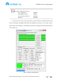
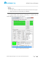
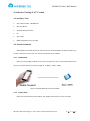
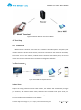
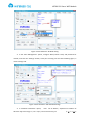
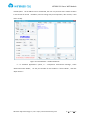
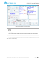
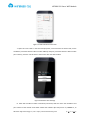
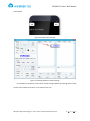
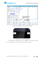
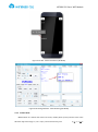
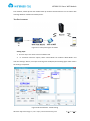
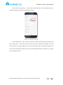
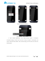
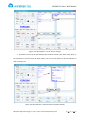
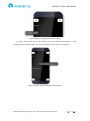
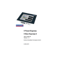
1
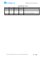
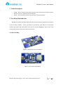
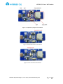
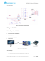
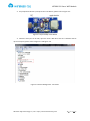
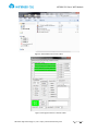
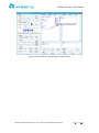
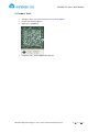
Xiao e WiFi Module (WT8266-S1) Extreme / Open / Small / Easy User Manual Version 2.0 2015 / 9 / 20 WT8266-S1 Xiao e WiFi Module Disclaimer and Copyright Notice Information in this document, including URL address for reference, may change without notice. Document "AS IT IS", WITHOUT ANY WARRANTY, including warranties of merchant ability、 for any particular purpose or non-infringement guarantee, and any proposal, any guarantee of specification or sample mentioned in other place. This document assumes no liability, including liability for infringement of any patent behavior of the use of this information in the document produced. This document is not to prohibit reverse speech or other ways to authorize any intellectual property permission, whether express or implication. Wi-Fi Alliance logos are owned by all the Wi-Fi Alliance. All trade names mentioned in the text, trademarks and registered trademarks are the property of their respective owners, and are hereby acknowledged. Note As the product upgrade or other reasons, this manual is may change. Shenzhen Wireless-Tag Technology Co., Ltd has right to modify the contents of this manual without any notice or warning. This manual is only as a guide,Wireless-Tag Technology Co., Ltd blind every effort to provide accurate information in this manual, but the Wireless-Tag blind manual does not ensure that there is no error, all statements in this manual, information and suggestions do not constitute any guarantee of express or implication. Symbol Conventions The following symbols may appear in this article, they are defined as follows. Symbol Description Text with this symbol indicates a potentially hazardous situation, which if ignored, could result in equipment damage, Warning data loss, performance degradation or unexpected results. Text with this mark is the additional information of main body Description Wireless-Tag Technology Co.,Ltd which is to emphasize and supplement http://www.wireless-tag.com 第 2 页 共 29 页 WT8266-S1 Xiao e WiFi Module Contents 1. TERM DESCRIPTION................................................................................................................ 4 2. TEST BOARD INTRODUCTION .................................................................................................. 5 2.1 PHYSICAL MAP............................................................................................................................ 5 2.2 SCHEMATICS ............................................................................................................................... 7 3. PROGRAM GUIDELINES........................................................................................................... 7 3.1 AUXILIARY TOOL AND CONDITIONS .................................................................................................. 7 3.2 TEST STEPS ................................................................................................................................. 7 4. SOFTWARE TESTING OF AT VERSION ..................................................................................... 12 4.1 AUXILIARY TOOL ........................................................................................................................ 12 4.2 TEST ENVIRONMENT................................................................................................................... 12 4.2.1 SoftAP Mode............................................................................................................... 12 4.2.2 Station Mode .............................................................................................................. 12 4.3 TEST STEPS ............................................................................................................................... 13 4.3.1 SoftAP Mode............................................................................................................... 13 4.3.2 Station Mode .............................................................................................................. 21 5. PRODUCT TRIAL .................................................................................................................... 29 Wireless-Tag Technology Co.,Ltd http://www.wireless-tag.com 第 3 页 共 29 页 WT8266-S1 Xiao e WiFi Module Amendment record Version V1.0 Changed by Lemme Time Reason 2015.08.24 Original Details Change Test Board picture; V2.0 Lemme 2015.09.20 Update Change Figure 2-6 Schematics of Test Baseboard; Change 4.2.1 and 4.2.2 description; Wireless-Tag Technology Co.,Ltd http://www.wireless-tag.com 第 4 页 共 29 页 WT8266-S1 Xiao e WiFi Module 1. Term Description SoftAP:That is a wireless access point just like a central node of the wireless network. Wireless router is a typical wireless access point. Station:That is wireless terminal, the terminal is a wireless network. 2. Test Board Introduction WT8266-S1 provides specialized UART_WiFi functional test board to facilitate the customers to test the Wi-Fi module . Via the test board, it can simulate serial devices to access WiFi network and realize data transmission, but also can simulate WT8266-S1 works as the main control chip to access data of other devices and control. 2.1 Physical Map Figure 2-1 Perspective View of Test Board Figure 2-2 Front View of Test Board Wireless-Tag Technology Co.,Ltd http://www.wireless-tag.com 第 5 页 共 29 页 WT8266-S1 Xiao e WiFi Module Figure 2-3 Explanatory Diagram of Test Board Figure 2-4 download mode of Test Board Figure 2-5 normal mode of Test Board Wireless-Tag Technology Co.,Ltd http://www.wireless-tag.com 第 6 页 共 29 页 WT8266-S1 Xiao e WiFi Module 2.2 Schematics Figure 2-6 Schematics of Test Baseboard 3. Program Guidelines 3.1 Auxiliary tool and Conditions Xiao e WiFi module(WT8266-S1) WiFi Test Board Xiao e WiFi Burn ToolsV1.2 Program Copy USB PC Minitool xiaoeWiFi Figure 3.1 Test Logic Diagram 3.2 Test Steps 1、To build test environment according to figure 3-1, figure 3-2 Wireless-Tag Technology Co.,Ltd http://www.wireless-tag.com 第 7 页 共 29 页 WT8266-S1 Xiao e WiFi Module 2、Use jumped test board J1, and press the reset button, please refer to figure 3-2: Figure 3.2 Physical Map of Test Board 3、Check the serial port on PC side, open the "Xiao e WiFi burn tool V1.2" software and set up the serial port, please refer to figure 3-3 and figure 3-4: Figure 3-3 Device Management - Serial Port Wireless-Tag Technology Co.,Ltd http://www.wireless-tag.com 第 8 页 共 29 页 WT8266-S1 Xiao e WiFi Module Figure 3-4 Executable File of Xiao e WiFi Figure 3-5 Program Tool V1.2 of Xiao e WiFi Wireless-Tag Technology Co.,Ltd http://www.wireless-tag.com 第 9 页 共 29 页 WT8266-S1 Xiao e WiFi Module Description: Program Place of File boot_v1.4(b1).bin user1.4096.new.4.bin esp_init_data_default.bin blank.bin 0x00000 0x1000 0x3fc000 0x3fe000 4、Import the files need to be programmed in program software "Download Path Config" and set SPI SPEED, SPI MODE, FLASH SIZE and BAUDTATE parameters, click "START" button, splats change from "Waiting" to "downloading", which means program download started, please refer to figure 3-6: Figure 3-6 Program Downloading Wireless-Tag Technology Co.,Ltd http://www.wireless-tag.com 第 10 页 共 29 页 WT8266-S1 Xiao e WiFi Module Description: Xiao eWiFi module use a 32 Mbit external FLASH, please pay attention when program Design of the baud rate is recommended to use 115200 bps; 4、In program software, splats change from "downloading" to "complete" means the program download is complete, please refer to figure 3-7: Figure 3-7 Program Download Complete Wireless-Tag Technology Co.,Ltd http://www.wireless-tag.com 第 11 页 共 29 页 WT8266-S1 Xiao e WiFi Module 4. Software Testing of AT Version 4.1 Auxiliary Tool Xiao e WiFi module(WT8266-S1) WiFi Test Board Andriod4.0 Version above PC Xiao e APP 8266 configuration tool ( PC side) 4.2 Test Environment WIFI module and mobile phone (or PC) need to be connected within the same network, you can also connect to a router, you can connect your phone to the module. 4.2.1 SoftAP Mode Phone (or PC) and WIFI module on the router, the phone (or PC) is connected directly to the router, the module link to the router through AT + CWJAP = "SSID", "PWD" Figure 4-1 SoftAP Network Connection Mode 4.2.2 Station Mode Phone (or PC) connected to the module, the module needs to be set in server mode. Wireless-Tag Technology Co.,Ltd http://www.wireless-tag.com 第 12 页 共 29 页 WT8266-S1 Xiao e WiFi Module Figure 4.2 Station Network Connection Mode 4.3 Test Steps 4.3.1 SoftAP Mode Module acts as a wireless access node in the network role, mobile phones, computers, WIFI modules and other wireless access devices, etc. can be connected to the module as the Station, formed into a LAN. In this example, module wireless connected with mobile phone, PC terminal monitor the module's data transceiver situation via configuration software. Test Environment: Figure 4-3 SoftAP Test System Diagram Setting Steps: 1. Open the testing software of Xiao eWiFi module, the software will automatically recognize port numbers, and module current mode, the baud rate to 115200. Click "Open serial port" button, the software will display "OK" in the receiving areas , it indicates that the module has been successfully connected with the test software. Wireless-Tag Technology Co.,Ltd http://www.wireless-tag.com 第 13 页 共 29 页 WT8266-S1 Xiao e WiFi Module Figure 4-3 Testing Software of Xiao eWiFi Module Figure 4-4 Test Software - Module Connection 2、In "common functions" options , please select "AP Mode" in "working mode" and click the "Settings Button". when serial receiving area shows "OK" , it means the setting is completed.Please refer to figure 4-5. Wireless-Tag Technology Co.,Ltd http://www.wireless-tag.com 第 14 页 共 29 页 WT8266-S1 Xiao e WiFi Module Figure 4-5 Test Software- AP Mode Setting 3、In the "WiFi Management" option, configure SSID (network name) and password for module, and click the "Settings" button, serial port receiving area will show following figure, it means setting is OK. Figure 4-6 Test Software -SSID Password Settings 4、In "Network Parameters" option, Wireless-Tag Technology Co.,Ltd read "AP IP Address", acquisition IP address of http://www.wireless-tag.com 第 15 页 共 29 页 WT8266-S1 Xiao e WiFi Module module (Note: the IP address can be customized, the user only need to enter custom IP values in the format of normal IP address, and can change it by write operation, after success, it will return to OK). Figure 4-7 Test Software--- Read and Write IP 5 、 In "Network Application" option, in " Transparent Transmission Settings", select "Multi-Connection Mode", set the port number for the module in "Server Mode" , and click "Open Service." Wireless-Tag Technology Co.,Ltd http://www.wireless-tag.com 第 16 页 共 29 页 WT8266-S1 Xiao e WiFi Module Figure 4-8 Test Software - Connection Mode Description: Here, the port number is "6666", later when test module with APP, need to be consistent. 6、Open the terminal device which needs to connect with the module, connected to module WiFi network in WiFi settings. Wireless-Tag Technology Co.,Ltd http://www.wireless-tag.com 第 17 页 共 29 页 WT8266-S1 Xiao e WiFi Module Figure 4-9 APP- Network Connection 7、Open the "Xiao e APP" in the terminal equipment, in the customer terminal mode, set the IP address (consistent with the WiFi module address) and port (consistent with the WiFi module port number), click the "TCP Protocol" and connect with the WiFi module. Figure 4-10 APP-IP Port Settings 8、After APP and WiFi module successfully connected, APP will return the IP address and port number of the module. Xiao eWiFi module test software (PC end) returns "0, CONNECT", as Wireless-Tag Technology Co.,Ltd http://www.wireless-tag.com 第 18 页 共 29 页 WT8266-S1 Xiao e WiFi Module shown below. Figure 4-11 APP-IP Port Settings Figure 4-12 Testing Software -IP Port Settings 9、Send data to the APP from Xiao e WiFi module testing software (PC) through WiFi module, need to select "Multi-Connection" in the transmission area. Wireless-Tag Technology Co.,Ltd http://www.wireless-tag.com 第 19 页 共 29 页 WT8266-S1 Xiao e WiFi Module Figure 4-13 Testing Software - Data Transmission (AP mode) Figure 4-14 APP - Data Receiving (AP Mode) 10、Send data to the module by the APP, input "WT8266-S1" in the input box , click send. On PC testing software, you can view the data transmitted from the APP. Wireless-Tag Technology Co.,Ltd http://www.wireless-tag.com 第 20 页 共 29 页 WT8266-S1 Xiao e WiFi Module Figure 4-15 APP - Data Transmission (AP Mode) Figure 4-16 Testing Software - Data Receiving (AP Mode) 4.3.2 Station Mode Module work as a station and connect to router, mobile phone (or PC) connect to the same Wireless-Tag Technology Co.,Ltd http://www.wireless-tag.com 第 21 页 共 29 页 WT8266-S1 Xiao e WiFi Module local network, mobile phone and module build up network communications so as to realize data exchange between module and mobile phone. Test Environment: Figure 4-17 Test System Figure of Station Setting Steps: 1、The first step is the same to that of softAP mode. 2、 In "Common Functions" option, select "Client Mode" for module's "Work Mode" and click the "Settings" button, serial port receiving area will display the following figure which means the setting is completed. Figure 4-18 Test Software - Mode Setting Wireless-Tag Technology Co.,Ltd http://www.wireless-tag.com 第 22 页 共 29 页 WT8266-S1 Xiao e WiFi Module 3、In the "WiFi Management" option, click "Scan WiFi", find existed WiFi network, set the network's name and password that need to add in"Join WiFi network" option. When serial reception area display as figure 4-20, it means complete to join in the network. Figure 4-19 Testing Software - Scan WiFi Figure 4-20 Test Software - Join WiFi Wireless-Tag Technology Co.,Ltd http://www.wireless-tag.com 第 23 页 共 29 页 WT8266-S1 Xiao e WiFi Module 4、Open the terminal device, connect the terminal device to WiFi network firstly, the network need to be consistent to that of WiFi module. Figure 4-21 APP-WiFi Settings 5、Open APP, select "server" mode, set the port to "6666" (random setting, consistent with the PC side), click "TCP Protocol" to enter the receive and transmission interface. Click the "Start" button in the upper right corner, so that the terminal device successfully created a TCP server. After successfully created, the server will automatically obtain an IP address, set a good server port before return. Wireless-Tag Technology Co.,Ltd http://www.wireless-tag.com 第 24 页 共 29 页 WT8266-S1 Xiao e WiFi Module Figure 4-22 APP- Server Settings Figure 4-23 APP- IP Port of Server 6 、 Select "Network Applications", select "Multi-Connection Mode" in "Transparent Transmission Settings", and then enter the server's IP and port number in "Client Mode", and click the "Multi-Connection Mode". After successful setting, the serial receive area returns the following figure. Wireless-Tag Technology Co.,Ltd http://www.wireless-tag.com 第 25 页 共 29 页 WT8266-S1 Xiao e WiFi Module Figure 4-24 Test Software - Server IP Port Settings 7、Sent data to server by the test software data via WiFi module, enter data "xiaoe_WiFi" in the transmission area and click "AT Send" button. You can see the data from PC test software in APP receiving area. Figure 4-25 Test Software - Data Transmission (Station Mode) Wireless-Tag Technology Co.,Ltd http://www.wireless-tag.com 第 26 页 共 29 页 WT8266-S1 Xiao e WiFi Module Figure 4-26 APP - Data Reception (Station Mode) 8、Server (APP) sends data to the module, input data "www.wireless-tag.com" in APP sending area , click "send" button, you can see the data sent from APP in receiving area. Figure 4-27 APP - Data Transmission (Station Mode) Wireless-Tag Technology Co.,Ltd http://www.wireless-tag.com 第 27 页 共 29 页 WT8266-S1 Xiao e WiFi Module Figure 4-28 Test Software - Data Reception (Station Mode) Wireless-Tag Technology Co.,Ltd http://www.wireless-tag.com 第 28 页 共 29 页 WT8266-S1 Xiao e WiFi Module 5. Product Trial Aliexpress store: http://www.aliexpress.com/store/1784058 Forum: bbs.wireless-tag.com QQ Group : 214946279 Support E-mail:[email protected] Wireless-Tag Technology Co.,Ltd http://www.wireless-tag.com 第 29 页 共 29 页