1
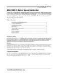
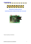
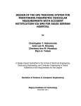
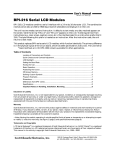
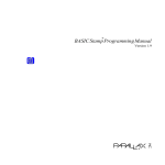
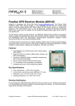
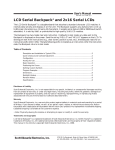
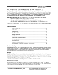
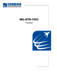
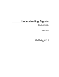
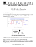
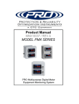
User’s Manual
SSC-ASD2 • v2.1 • 07/00 • pg 1
™
Mini SSC II Serial Servo Controller
The Mini SSC II is an electronic module that controls eight pulse-proportional (“hobby”) servos according
to instructions received serially at 2400 or 9600 baud. Two Mini SSC II units can share the same serial
line to control a total of 16 servos. This addressability is expandable—you can order units programmed
with other ranges of servo addresses so that a total of up to 32 Mini SSC IIs (controlling up to 255
servos) can share a single serial line.
Table of Contents
Connections and Configuration Jumpers ..................................................................................2
Configuring the Mini SSC II.......................................................................................................2
Connecting the Mini SSC II .......................................................................................................3
Initial Checkout..........................................................................................................................5
Programming for the Mini SSC II ..............................................................................................5
Multiple Mini SSCs ....................................................................................................................5
Theory of Operation ..................................................................................................................6
Program Examples....................................................................................................................7
Disclaimer of Liability
Scott Edwards Electronics, Inc. is not responsible for any special, incidental, or consequential damages resulting
from any breach of warranty, or under any legal theory, including lost profits, downtime, goodwill, damage to or
replacement of equipment or property, and any costs or recovering, reprogramming, or reproducing of data
associated with the use of the hardware or software described herein.
Warranty
Scott Edwards Electronics, Inc. warrants this product against defects in materials and workmanship for a period
of 90 days. If you discover a defect, we will, at our option, repair, replace, or refund the purchase price. Return
the product with a description of the problem. We will return your product or its replacement via standard shipping.
Expedited shipping is available at the customer’s expense.
• Note: Physically abusing the module, or attempting to repair or modify it, voids this warranty.
Trademarks and Copyrights
Mini SSC™ is a trademark of Scott Edwards Electronics, Inc.; BASIC Stamp® is a registered trademark of Parallax
Inc. All trademarked names referenced herein are the property of their respective holders. This manual in its
entirety is copyright Scott Edwards Electronics, Inc., 1999.
Scott Edwards Electronics, Inc.
1939 S. Frontage Road, Suite F, Sierra Vista, AZ 85635 USA
ph: 520-459-4802 • fax: 520-459-0623 • www.seetron.com
User’s Manual
SSC-ASD2 • v2.1 • 07/00 • pg 2
Connections and Configuration Jumpers
Figure 1 shows the layout of the Mini SSC II circuit board with the locations of connectors and
configuration jumpers.
Serial Input
(SSC-CBL; see figs. 2, 3)
configuration jumpers
Jumper
Function
Power for SSC
(9V battery snap)
off
on
Description
Serial in
always never
Serial in
always never
Do not jumper!
Do not jumper!
range
90°
180°
Range of motion
identification
0–7
8–15
Servo addresses
baud rate
2400
9600
Baud rate
to servo
Red wire is +
connection for
power—do not
reverse.
PWM
+V (red)
notch
GND (black)
Power for Servos
(4.8–6Vdc)
servo
connector
servo
connectors
36.0 by 54 mm
(1.4 by 2.1 in.)
servo header
servo
number
Do not reverse power polarity, even momentarily. Reversed power will destroy the electronics.
Do not exceed 10V into SSC 9V input. Overvoltage may damage the unit or shorten its life.
The “phone” jack is for serial input only. Connecting it to the telephone system will damage the unit.
Figure 1. Layout of the Mini SSC II circuit board.
Configuring the Mini SSC II
The Mini SSC II’s default configuration (all jumpers removed) is:
2400 baud • servos 0 through 7 • range of motion = 90°
To change a setting, install a jumper block across the appropriate pair of header posts
as shown in the drawing at right. Changes take effect the next time the SSC is powered
Here are more details on the configuration options:
(R)ange: With no jumper at R, the Mini SSC II controls servos over a 90° range of motion. Servos’
positions are expressed in units from 0 to 254, so each unit corresponds to a 0.36° change in the servo’s
position. With a jumper at R, the Mini SSC II controls servos over as much as 180°, with each unit
corresponding to a 0.72° change in position.
Scott Edwards Electronics, Inc.
1939 S. Frontage Road, Suite F, Sierra Vista, AZ 85635 USA
ph: 520-459-4802 • fax: 520-459-0623 • www.seetron.com
User’s Manual
SSC-ASD2 • v2.1 • 07/00 • pg 3
Configuring the Mini SSC II (continued)
Note Regarding Range: Some servos cannot move through a 180° range. They may stall when
positions less than 50 or greater than 200 are used with the Mini SSC II in 180° mode. Always check
out unfamiliar servos before using them with the Mini SSC II in 180° mode. Move the servo a few units
at a time toward the end of travel and see whether it stalls. If it does, either use the servo only in 90°
mode, or restrict position values to the safe range.
Please understand that servos are designed for 90° motion. The 180° mode exploits additional range
that is meant as allowance for mechanical and electrical tolerances. In other words, it cheats a little
to allow you to get the most from a given servo. There’s nothing wrong with a servo that won’t do 180°.
(I)dentification: With no jumper at I, servo addresses match the numbers printed next to the servo
headers—0 through 7. With a jumper at I, the Mini SSC adds 8 to these addresses, so that the servo
connected to “0” is addressed as 8, “1” as 9 ... and “7” as 15. This allows you to connect two Mini SSC
IIs to the same serial port and address each of the servos individually. See Multiple Mini SSCs for
information on controlling more Mini SSC IIs from a single serial port.
(B)aud: With no jumper at B, the Mini SSC II receives serial data at 2400 baud; with B jumpered the
baud rate is 9600. In either case, the data should be sent as 8 data bits, no parity, 1 (or more) stop
bit(s); abbreviated N81. In addition, the data should be inverted—just the way it comes from a standard
Connecting the Mini SSC II
Servos: The Mini SSC II connector accepts standard three-conductor servo plugs (e.g., Futaba-J
connectors). See figure 1 for the correct way to attach these connectors.
Servo Power: Connect power for the servos (4.8 to 6Vdc) to the red (+) and black (–) wires marked
SVO on the Mini SSC II board. Do not reverse + and –, even momentarily. This will damage the
servos. For a power source, use a four-pack of alkaline C or D cells. For an ac power supply, use a
regulated linear (not switching) supply rated for 5Vdc at 1A (or more). For more specific power-supply
recommendations, see www.seetron.com/ssc_faq.htm.
Mini SSC II Power: Connect a 9V battery to the battery snap. If you want to use another power
source, cut off the snap and connect 7 to 15Vdc to the wires, + to red and – to black. Do not reverse
+ and –, even momentarily. This can damage the electronics. The SSC power input is protected
against accidental 9V battery reversal, but higher input voltages can defeat this protection.
Serial Input: The Mini SSC II requires only two connections to a computer—serial data and signal
ground. There are two places to make these connections; a modular ‘phone’ jack and two pairs of pins
marked S(in) on the configuration header. It doesn’t matter which you use—pick the connection that
is most convenient.
With single-board computers like the BASIC Stamp® you will probably
use the header pins. Connect the Stamp I/O pin that your program will
use for serial output to S on the Mini SSC II. This will be one of pins 0—7
on the Stamp I, or pins P0—P7 on the BS2. (Don’t use BS2 pin Sout; it’s
for communicating with your PC during programming.) In either case,
connect Stamp Ground (Vss) to G.
serial
data
signal
ground
Note that there are two S pins and two G pins. These make a convenient tie point for connecting
multiple Mini SSC IIs to the same serial input. See Multiple Mini SSCs.
Scott Edwards Electronics, Inc.
1939 S. Frontage Road, Suite F, Sierra Vista, AZ 85635 USA
ph: 520-459-4802 • fax: 520-459-0623 • www.seetron.com
User’s Manual
SSC-ASD2 • v2.1 • 07/00 • pg 4
DB-9 Female
GREEN
(SOLDER SIDE)
Serial
1
5
Phone Base (not handset) Cable
GND
RED and BLACK unused
YELLOW
Figure 2. Wiring DB9 serial connector to a modular cable for use with SSC.
Connecting the Mini SSC II (continued)
Figure 2 above shows how to wire an SSC cable for use with the DB9 connector found on PCs and other
computers. If you prefer not to make your own cable, a ready-made one is available from Scott Edwards
Electronics Inc. as part number SSC-CBL (online, www.seetron.com). You may purchase the components
used in this cable from James Electronics (www.jameco.com or 1-800-831-4242). Figure 3 shows how
the cable is assembled:
DB-to-modular adapter
7-foot modular cable
(Jameco PN 115553)
DB9 female: Jameco PN 114737
Adapter Setup /DB9
YELLOW:
GREEN:
RED:
BLACK:
pin 5
pin 3
cut off
cut off
Figure 3. Solderless SSC cable (equivalent to SSC-CBL).
The DB9-to-modular adapter comes disassembled. To assemble it, push the pin sockets into the numbered
holes in the housing as indicated in the drawing above. Snap the adapter housing together and plug
in the modular cable. Note that you can use most any modular cable intended for connecting a phone
to the wall jack. The only requirement is that the cable be a four-wire type (with yellow, green, red,
and black wires all connected). Two-wire cables that come with cheap telephones have only the red and
black wires, and won’t work. You can check by looking through the transparent phone-plug body—if
you see four wires, it’s OK.
NEVER connect the Mini SSC II to the phone line!
25-pin Serial Ports: These are almost extinct, but if your computer has one, just use a commercial
DB25-to-DB9 adapter and one of the cables shown above.
Scott Edwards Electronics, Inc.
1939 S. Frontage Road, Suite F, Sierra Vista, AZ 85635 USA
ph: 520-459-4802 • fax: 520-459-0623 • www.seetron.com
User’s Manual
SSC-ASD2 • v2.1 • 07/00 • pg 5
Initial Checkout
When the Mini SSC II is first powered up, it will turn on the Sync LED and move all servos to the
centered position (see Theory of Operation). Once you have connected servos, servo power, and Mini
SSC power, the servos will immediately swing to center. If they are already centered, they may not
move much, but you can confirm proper operation by trying to move a servo with your fingers (gently).
The servo will resist your efforts to move it. If it doesn’t, recheck servo and power connections.
The Green Light: At powerup, the green Sync LED indicates not only that the Mini SSC II is receiving
power, but also that its microcontroller is working properly (passed startup initialization). If the green
light comes on, but servos don’t appear to be responding correctly, the problem is most likely with servo
connections, servo power, or serial hookup, not with the Mini SSC II.
Serial Checkout: To verify proper serial hookup, run one of the demonstration programs, a commercial
Mini SSC II software package (see www.seetron.com/ssc.htm for a list), or a serial-test program (such
as Serial Sender, available free from www.seetron.com/dl.shtml). Make sure that the program’s baud
rate matches the Mini SSC II’s setting, and that the I/O pin or comm port selected for serial output is
the one the Mini SSC II is connected to.
Programming for the Mini SSC II
To command a servo to a new position requires sending three bytes at the appropriate serial rate (2400
or 9600 baud, depending on the setting of the B jumper; see Configuring the Mini SSC II). These bytes
Byte 1
Byte 2
Byte 3
[sync marker (255)]
[servo # (0-254)
[position (0-254)]
These must be sent as individual byte values, not as text representations of numbers as you might
type at a keyboard. The example programs at the back of this manual show how to convert numbers
to byte values. In PBASIC, you just omit any text- formatting functions (# for the BS1; DEC, HEX, ?,
etc. for the BS2). In other BASICs, use the CHR$ function to convert numbers to bytes.
The Sync LED on the Mini SSC II board can help you debug your serial routines. It lights steadily
when power is first applied to the board and stays on until the first complete three-byte instruction
is received. Thereafter, the LED lights only after a valid sync marker and servo address are received.
It stays on until a position byte is received, then turns off. If your program is sending lots of data to
the Mini SSC II, the LED will appear to light steadily, but will actually be blinking very rapidly.
Windows 95/98/NT programming: A 32-bit Windows DLL is available free from our web site at
www.seetron.com/ssc_an1.htm. Documentation includes a complete description of the DLL, plus program
examples for Microsoft Visual BASIC 6 and Borland Delphi 5. The DLL may be used with any Windows
programming environment that supports DLLs.
Multiple Mini SSCs
To control two Mini SSC IIs, connect them in parallel to the same serial line; see wiring suggestions
on the next page. Set both units for the same baud rate. Install a jumper at the I configuration header
of one; leave this header open on the other. Address the servos as follows:
Jumper at I?
no
yes
Scott Edwards Electronics, Inc.
Servo Numbers
0–7
8–15
1939 S. Frontage Road, Suite F, Sierra Vista, AZ 85635 USA
ph: 520-459-4802 • fax: 520-459-0623 • www.seetron.com
User’s Manual
SSC-ASD2 • v2.1 • 07/00 • pg 6
Multiple Mini SSCs (continued)
Wiring suggestions for multiple Mini SSC IIs: Once you have one Mini SSC II connected to a
computer, connecting additional units is easy. Just wire the S and G pins of the first Mini SSC II to
the S and G pins of the second. Do the same for the second and third, third and fourth, and so on. Since
there are two S pins and two G pins on each Mini SSC II, this is simple.
To make these connections without soldering, use Connectamundos jumper wires (CNX-010) from Scott
Edwards Electronics, Inc. These have sockets that fit the pins on the Mini SSC II board (or any 0.025"
More than 16 servos: With a jumper installed at I, the Mini SSC II adds 8 to the servo addresses,
so that servo 0’s address is 8, servo 1 is 9...and servo 7 is 15. If you need to control more than 16 servos,
you may special-order Mini SSC IIs with higher address ranges from the manufacturer. For example,
your third and fourth Mini SSC IIs would have a base address (the address corresponding to servo 0
with no I jumper) of 16. Part numbers for these special Mini SSC IIs is SSC-ASD2-n, where n is the
base servo number. The table below lists the first five part numbers and the range of servo numbers
they cover.
Part Number
Servo #s (no jumper at I)
SSC-ASD2 (standard)
SSC-ASD2-16
SSC-ASD2-32
SSC-ASD2-48
SSC-ASD2-64
Servo #s (jumper at I)
0—7
16—23
32—39
48—55
64—71
8—15
24—31
40—47
56—63
72—79
Theory of Operation
Pulse-proportional servos are designed for use in radio-controlled (R/C) cars, boats and planes. They
provide precise control for steering, throttle, rudder, etc. using a signal that is easy to transmit and
receive. The signal consists of pulses ranging from 1 to 2
1.5 ms
milliseconds long, repeated 60 times a second. The servo
positions its output shaft in proportion to the width of the
servo
pulse, as shown in Figure 5.
centered
In radio-control applications, a servo needs no more than a
90° range of motion, since it is usually driving a crank
mechanism that can’t move more than 90°. So when you send
pulses within the manufacturer-specified range of 1 to 2 ms,
you get a 90° range of motion. With no jumper at the (R)ange
header, a position value of 0 corresponds to 1-ms pulses; 254
to 2.016 ms. A 1-unit change in position value produces a 4microsecond change in pulse width. Positioning resolution
is 0.36°/unit (90°/250).
1 ms
servo
–45°
2 ms
servo
+45°
Figure 5. Servos are controlled by
Most servos have more than 90° of mechanical range, though,
1to 2-ms pulses repeating at 60Hz.
in order to allow adjustment for component variations,
mounting position, etc. The Mini SSC II lets you use this
extra range. With a jumper at (R)ange, a position value of 0 corresponds to 0.5-ms pulse; 254 to 2.53
ms. A 1-unit change in position value produces a 8-microsecond change in pulse width. Positioning
resolution is 0.72°/unit (180°/250).
Scott Edwards Electronics, Inc.
1939 S. Frontage Road, Suite F, Sierra Vista, AZ 85635 USA
ph: 520-459-4802 • fax: 520-459-0623 • www.seetron.com
User’s Manual
SSC-ASD2 • v2.1 • 07/00 • pg 7
Program Examples
' Listing 1. BASIC Stamp I Program Demonstrating the Mini SSC
' Program: SCAN.BAS (BS1 servo control demo)
' This program demonstrates servo control using the MiniSSC.
' It commands servo 0 slowly and smoothly through its full
' range of travel. To run this program, leave all configuration
' jumpers off the Mini SSC board. Connect:
'
BS1
Mini SSC
Purpose
'
------------------------'
pin0
S(in) pin S
Serial signal
'
Vss
S(in) pin G
Ground
' Plug a servo into Mini SSC output 0 and connect power as described
' in the manual. Run this program. The servo will slowly scan back
' and forth. Change for/next step values to change servo movement.
SYMBOL svo = 0
' Use servo 0.
SYMBOL sync = 255
' Mini SSC sync byte.
SYMBOL pos = b2
' Byte variable b2 holds position value.
again:
for pos = 0 to 254 step 1
' Rotate clockwise in 1-unit steps.
serout 0,n2400,(sync,svo,pos) ' Command the Mini SSC.
next pos ' Next position.
for pos = 254 to 0 step -1
' Rotate counter-clock, 1-unit steps.
serout 0,n2400,(sync,svo,pos) ' Command the mini SSC.
next pos
' Next position.
goto again
' Do it again.
' Listing 2. BASIC Stamp II Program Demonstrating the Mini SSC
' Program: SCAN.BS2 (BS2 servo control demo)
' This program demonstrates servo control using the MiniSSC.
' It commands servo 0 slowly and smoothly through its full
' range of travel. To run this program, install a jumper at
' B on the Mini SSC board; leave all other jumpers off.
' Connect:
'
BS2
Mini SSC
Purpose
'
------------------------'
P0
S(in) pin S
Serial signal
'
Vss
S(in) pin G
Ground
' Plug a servo into Mini SSC output 0 and connect power as described
' in the manual. Run this program. The servo will slowly scan back
' and forth. Try changing the step values in the for/next loops
' to see the effect on servo movement.
svo con 0 ' Use servo 0.
sync con 255
' Mini SSC sync byte.
pos var byte
' Byte variable holds position value.
n96n con $4054
' Baudmode: 9600 baud (BS2-SX, change to $40F0).
n24n con $418D
' Baudmode: 2400-baud (BS2-SX, change to $43FD).
(more on next page)
Scott Edwards Electronics, Inc.
1939 S. Frontage Road, Suite F, Sierra Vista, AZ 85635 USA
ph: 520-459-4802 • fax: 520-459-0623 • www.seetron.com
User’s Manual
SSC-ASD2 • v2.1 • 07/00 • pg 8
' BS2 program example, continued.
again:
for pos = 0 to 254 step 1
'
serout 0,n96n,[sync,svo,pos]
'
next
'
for pos = 254 to 0 step 1
'
serout 0,n96n,[sync,svo,pos]
'
next
'
goto again
'
Rotate clockwise in 1-unit steps.
Command the mini SSC.
Next position.
Rotate counter-clock, 1-unit steps.
Command the mini SSC.
Next position.
Do it again.
' Listing 3. QBASIC Program for PCs Demonstrating the Mini SSC
' Note:This program is written for QBASIC, an old, but still common
' MS-DOS programming language. For programming under Windows 95 or
' greater with Visual BASIC see www.seetron.com/ssc_an1.htm .
DEFINT A-Z
Sync.byte = 255
' The line below assumes that the B jumper is installed for
' 9600-baud operation.
OPEN "com1:9600,N,8,1,CD0,CS0,DS0,OP0" FOR OUTPUT AS #1
CLS
PRINT "
MINI SERIAL SERVO CONTROLLER"
PRINT : PRINT
PRINT "At the prompt, type the servo number (0 to 7), a comma,
PRINT "and a position value (0 to 254)."
PRINT "Press <CNTL> - <Break> to end."
Again:
LOCATE 8, 1
PRINT "
"
LOCATE 8, 1
INPUT "Servo,position>", Servo, Position
' Perform some basic error trapping
IF Servo > 7 THEN Servo = 7
IF Servo < 0 THEN Servo = 0
IF Position > 254 THEN Position = 254
IF Position < 0 THEN Position = 0
PRINT #1, CHR$(Sync.byte); CHR$(Servo); CHR$(Position);
GOTO Again
For more Mini SSC program examples
plus links to users’ Mini SSC projects
see www.seetron.com/ssc.htm
Scott Edwards Electronics, Inc.
1939 S. Frontage Road, Suite F, Sierra Vista, AZ 85635 USA
ph: 520-459-4802 • fax: 520-459-0623 • www.seetron.com