1
Micrel, Inc.
MIC2870 Evaluation Board
Evaluation Board Description
The flash inhibit (FI) pin can be used to synchronize the
flash current to a handset GSM pulse event to prevent
excessive battery droop. When FEN and FI pins are both
high, the flash mode current is limited to the torch mode
current setting. The FI Pin is also functional when the flash
2
mode current is enabled through the I C flash register.
Torch Mode
The maximum torch mode level can be adjusted through
an external resistor connecting to the TRSET pin
according to Equation 2:
ILED(MAX) =
Flash Mode
The maximum current level in the flash mode is 750mA
per channel. This current level can be adjusted through an
external resistor connecting to the FRSET pin according to
Equation 1:
7500
R FRSET
Like the flash mode current, the torch mode current can be
set to a fraction of the maximum torch mode level (either
default or set by the TRSET resistor) by selecting the
desired torch current level percentage in the torch register
2
(Address 02h) through the I C interface. The torch current
is the product of the maximum torch current setting and
the percentage selected in the torch register.
Eq. 1
Alternatively, the default maximum value of 750mA per
channel is used when the FRSET pin is grounded.
Overvoltage Protection
When the output voltage rises above the OVP threshold,
the MIC2870 is turned off automatically to avoid
permanent damage to the IC.
The flash mode current can be initiated at the preset
FRSET brightness level by asserting FEN pin high or by
2
setting the I C flash control register (address 01h) for the
desired flash duration, subjected to the flash safety timeout
setting. The flash mode current is terminated when the
2
FEN pin is brought low and the I C flash register is
cleared.
Open Circuit Detection
The open-circuit detector (OCD) is active only when the
LED current regulator is turned on. When the external LED
is missing or fails open, the LED1/2 pin voltage is pulled to
near the ground potential by the internal current sink. If
both LEDs are open or missing, the open-circuit detector
would force the boost regulator and LED current regulator
to turn off. The MIC2870 will try to turn on the boost
regulator and LED current regulator again after a 100ms
timeout. However, in most practical cases, the boost
output voltage would rise above the OVP threshold, when
both LED channels have an open fault. The OVP function
would cause the MIC2870 to shut down.
Flash mode current can be adjusted to a fraction of the
maximum flash mode level (either default or set by the
FRSET resistor) by selecting the desired flash current level
percentage in the flash control register (Address 01h)
2
through the I C interface. The flash current is the product
of the maximum flash current setting and the percentage
selected in the flash register.
The flash safety timeout feature automatically shuts down
the flash current if the flash mode is enabled for an
extended period of time. Refer to the “Flash Safety Timer”
setting in Table 4.
September 24, 2013
Eq. 2
Alternatively, the default maximum value of 187.5mA per
channel is used when the TRSET pin is grounded. The
torch mode operation is activated by asserting the TEN pin
2
high or by setting the I C torch register (address 02h) for
the desired duration. The torch mode current is terminated
2
when the TEN pin is brought low and the I C torch register
is cleared.
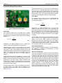
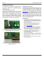
Figure 1. MIC2870 Evaluation Board
ILED(MAX) =
7500
4R TRSET
3
Revision 1.2