1
Micrel, Inc.
MIC2870 Evaluation Board
Getting Started (Continued)
5. Enable/Disable flash inhibit.
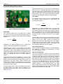
The FI (TP3 upper pin) is the flash inhibit pin. When
this pin is high in flash mode, both LED1 (D1) and
LED2 (D2) currents are changed from the flash mode
current level to the torch mode current level. When this
pin is low, both LED1 (D1) and LED2 (D2) currents are
changed from torch mode current level back to the
original flash mode current level. Setting a jumper at
TP3 can connect FI to VIN through a resistor. If this
pin is left floating, it is pulled-down internally by a builtin 1µA current source when the device is enabled.
6. Graphic user interface support.
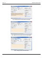
Graphical user interface software can be used with the
MICUSB Dongle EV allowing configuration and testing
of the MIC2870 with a standard computer. For more
detail, refer to the Evaluation Software section.
September 24, 2013
2
Revision 1.2