1
Micrel, Inc.
MIC2870 Evaluation Board
Evaluation Software
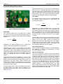
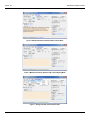
The MIC2870 evaluation software graphic user interface
(GUI) is shown in Figure 5 and Figure 6. When the
evaluation software is just started, it is default in offline
mode as shown on the right of the top menu bar in Figure
5. The offline mode is only for running the software without
the communication or connection with the MIC2870
evaluation board.
At the right side of the GUI panel which is the MIC2870
Control panel, user can perform the following MIC2870
operation:
1. Check or uncheck the “Enabled” option to enable or
disable the MIC2870 device.
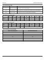
2. Change the flash safety timer duration setting from 0
to 7 which corresponding to 8 options from 156ms to
1250ms. Please refer to Table 4 for details.
To control the MIC2870 evaluation board with the software
GUI, the user firstly has to click the “Test” button. If the
connection from the PC to the dongle and then to the
MIC2870 EVB is fine as instructed in Connecting the USB2
to-I C Adapter section and in steps 4 and 5 in the Getting
Started section, the “Target OK” will be shown up at the
status bar at the bottom of the GUI as shown Figure 5.
3. Adjust the flash brightness with the slide bar from
100% to 18% of the maximum LED current in flash
mode in 16 steps. The maximum is on the left and the
minimum is on the right.
4. Fire flash or reset flash by clicking the flash mode
enable button.
If the connection is not good, the “Target Not Detected” will
be shown up at the status bar and the user has to check
with the cable connections before proceeding to the next
step. When the “Target OK” status is shown, the user can
click on the “Offline Mode” at the menu bar to change it to
“Direct Editing Mode”. When the “Direct Editing Mode” is
shown up at the top menu bar and the “Direct Editing
Mode Active” is indicated at the status bar as shown in
Figure 6, the software GUI allows the user to control the
operation of the MIC2870 evaluation board.
5. Check or uncheck flash inhibit option to enable or
disable the flash inhibit function.
6. Adjust the torch brightness with the slide bar from
100% to 18% of the maximum LED current in torch
mode in 16 steps. The maximum is on the left and the
minimum is on the right.
7. Set or reset torch by clicking on the torch mode enable
button.
8. Click the “Breath” button, “Strobe” button, and set
delay time options for special effects demonstration.
Introduction to the GUI Panel
At the left side of the GUI panel, user can check with the
MIC2870 registers information and perform read and write
operation to the IC registers. At the middle of the GUI
panel, user can click the “Enable” option to enable the
register polling.
9. Fault indication will be shown at the bottom of the
control panel if the register polling is enabled and fault
conditions are detected. The current detected fault
value can be cleared by clicking the “Clear” button.
2
Setting of I C Data Rate
2
The data rate of the I C communication can be set at the
2
pull-down menu from the “I C” menu at the top menu bar
as shown in Figure 7. User can set the data rate to
100kbps, 400kbps, or 3.4Mbps from the pull-down menu.
September 24, 2013
9
Revision 1.2