1
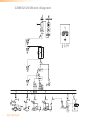
COM12/24 Mk2
User Manual
www.audac.eu
2
Index
Introduction5
COM12/24 Block Diagram6
Precautions7
Safety requirements7
Caution servicing7
EC Declaration of Conformity7
Waste of Electrical and Electronic Equipment (WEEE)
8
Caution8
Chapter 1: Pin connections and connectors 9
Connection standards9
Chapter 2: Front & rear panel
11
Front panel overview11
Front panel description11
Rear panel overview12
Rear panel description12
Chapter 3: Setting up the system
14
Connecting the loudspeakers14
Connecting the audio sources14
Priorities16
Phantom power16
Using the priority mute contact17
Pre-announcement chime selection17
Chapter 4: Additional information18
Technical specifications18
Notes20
3
4
Introduction
Public address amplifiers
The COM12/COM24 public address amplifier was developed as an easy to use, flexible
solution for multifunctional use.
During the development of the COM12/COM24, the AUDAC-engineers wanted to achieve
fourn goals:
- Delivering a flexible audio solution to control multiple functions
- Easy to use
- Excellent sound quality
- Modern and advanced design
The COM12/COM24 has 2 stereo unbalanced line level inputs, 2 mono balanced line level
inputs, 2 mono balanced line level inputs with priority settings and phantom power, 5 high
impedance 100V mono output zones, 1 low impedance 4ohm mono output zone, a link input
and output, an amp input and pre-amp output, a remote microphone input and the possibility
to connect a telephone pager unit.
The COM12/COM24 can be used in commercial applications such as restaurants, hotels,
shops, warehouses, professional offices, public buildings, …
A simple example: when installed in a shop, you could connect: a tuner to play your favorite
radiostation, a microphone to make announcements, a telephone pager, … and off course
the doorbell of the shop.
5
COM12/24 Block diagram
6
Precautions
READ FOLLOWING INSTRUCTIONS FOR YOUR OWN SAFETY
ALWAYS KEEP THESE INSTRUCTIONS. NEVER THROW THEM AWAY
ALWAYS HANDLE THIS UNIT WITH CARE
HEED ALL WARNINGS
FOLLOW ALL INSTRUCTIONS
NEVER EXPOSE THIS EQUIPMENT TO RAIN, MOISTURE, ANY DRIPPING OR SPLASHING
LIQUID. AND NEVER PLACE AN OBJECT FILLED WITH LIQUID ON TOP OF THIS DEVICE.
DO NOT PLACE THIS UNIT IN AN ENCLOSED ENVIRONMENT SUCH AS A BOOKSHELF
OR CLOSET. ENSURE THERE IS ADEQUATE VENTILATION TO COOL THE UNIT. DO NOT
BLOCK THE VENTILATION OPENINGS.
DO NOT STICK ANY OBJECTS THROUGH THE VENTILATION OPENINGS.
DO NOT INSTALL THIS UNIT NEAR ANY HEAT SOURCES SUCH AS RADIATORS OR
OTHER APPARATUS THAT PRODUCE HEAT
DO NOT PLACE THIS UNIT IN ENVIRONMENTS WHICH CONTAIN HIGH LEVELS OF DUST,
HEAT, MOISTURE OR VIBRATION
THIS UNIT IS DEVELOPED FOR INDOOR USE ONLY. DO NOT USE IT OUTDOORS
PLACE THE UNIT ON A STABLE BASE OR MOUNT IT IN A STABLE RACK
ONLY USE ATTACHMENTS & ACCESSORIES SPECIFIED BY THE MANUFACTURER
UNPLUG THIS APPARATUS DURING LIGHTNING STORMS OR WHEN UNUSED FOR LONG
PERIODS OF TIME
ONLY CONNECT THIS UNIT TO A MAINS SOCKET OUTLET WITH PROTECTIVE
EARTHING CONNECTION
CAUTION - SERVICING
This product contains no user serviceable parts. Refer all servicing to
qualified service personnel. Do not perform any servicing (unless you
are qualified to)
EC DECLARATION OF CONFORMITY
This product conforms to all the essential requirements and further
relevant specifications described in following directives: 2004/108/EC
(EMC) and 2006/95/EC (LVD)
7
WASTE ELECTRICAL AND ELECTRONIC EQUIPMENT (WEEE)
The WEEE marking indicates that this product should not be disposed
with regular houshold waste at the end of its life cycle. This regulation
is created to prevent any possible harm to the environment or human
health.
This product is developed and manufactured with high quality materials
and components which can be recycled and/or reused. Please
dispose this product at your local collection point or recycling centre
for electrical and electronic waste. This will make sure that it will be
recycled on an environmentally friendly manner, and will help to protect
the environment in which we all live.
CAUTION
The symbols shown are internationally recognized symbols that warn about potentional
hazards of electrical products. The lightning flash with arrowpoint in an equilateral
triangle means that the unit contains dangerous voltages. The exclamation point in
an equilateral triangle indicates that it is necessary for the user to refer to the users
manual.
These symbols warn that there are no user serviceable parts inside the unit. Do not
open the unit. Do not attempt to service the unit yourself. Refer all servicing to qualified
personnel. Opening the chassis for any reason will void the manufacturer’s warranty. Do
not get the unit wet. If liquid is spilled on the unit, shut it off immediately and take it to a
dealer for service. Disconnect the unit during storms to prevent damage.
8
Chapter 1
Pin connections and connectors
CONNECTION STANDARDS
The in- and output connections for AUDAC audio equipment are performed corresponding
to international wiring standards for professional audio equipment.
RCA (Cinch):
For unbalanced line input connections.
Tip: Signal
White:Left
Sleeve:Ground
Red: Right
XLR:
For balanced signal input connections
Pin 1: Ground
Pin 2: Signal +
Pin 3: Signal -
6.3 mm (1/4”) balanced Jack:
For balanced line in & output connections.
Tip: Signal +
Ring: Signal Sleeve: Ground
6.3 mm (1/4”) unbalanced Jack:
For unbalanced line in & output connections.
Tip:Signal
Sleeve: Ground
9
10
Chapter 2
Front & rear panel
Front panel overview
Front panel description
The front panel for both COM12 and COM24 amplifiers is identical and enables you to
control the level for every input and the overal output volume. A two band tone control
is provided for the main output, allowing adjustment of the overal system frequency
response while zone (output) switches allows enabling / disabling of the different speaker
zone outputs.
Input level controls:
Using the input level controls, the individual level for each connected input can be set.
This way, multiple inputs can be mixed with each other between zero and maximum level.
Chime:
When pressing the chime button, the selected chime tone as pre-announcement for
paging will be played once (identical as a contact closure on remote mic ‘SW’ terminal on
rear panel). How the selection for this pre-announcement tone can be done, is described
in a later chapter of this instruction manual.
Two band tone control:
Using the bass and treble rotary dials, the overall system frequency response can be
adjusted within a range of ± 12 dB. The level will be increased while clockwise rotating,
while counter-clockwise will result in a level decrease. In center position, both dials are
set to neutral level.
Master volume control:
Using the master volume control, the overal system volume will be adjusted in a range
between minimum and maximum level.
LED indicators:
The current system operation is indicated on the 7 digit LED bar graph. The bottom LED is
the power indicator which illuminates in blue colour when the system is switched on. The
5 LED’s above monitor the current output level within a range of -20 dB and +3 dB, while
the upper protect LED (red) illuminates when the system is in protect mode (some failure /
overload on the outputs occured). All outputs will be muted when this LED illuminates.
11
Zone 1-5 (output) switches:
The different connected loudspeaker lines (1-5) can be switched on and off by pressing
the switches with the corresponding numbers. When the ‘All’ switch is pressed, all
loudspeaker outputs will be enabled.
Rear panel overview
Rear panel description
The rear panel for both COM12 and COM24 is identical and contains all connection and
configuration controls. Configuration controls include the settings which should be made
once when setting up the system and doesn’t have to be changed by the user afterwards.
Power inlet:
The AC power inlet is implemented on the COM12/24 series amplifiers using a fixed lead
with fixed plug, depending of the amplifier region. (CEE 7/7 for EU, type G for UK, ... ) A
fuse holder with mains fuse is located on top of the power inlet. When replacing the fuse,
make sure the replacement matches the specifications of the original fuse. (T2AL/250V
for COM12 & T4AL/250V for COM24)
Loudspeaker output connections (Terminal block connectors):
Output connections for both low impedance and constant voltage distributed audio
systems are provided. The low impedance loudspeaker output is connected using a 2-pin
terminal block, while different zone (1-5) outputs are provided on a 10-pin terminal
block connector. More information about loudspeaker output connections is described in a
further chapter of this instruction manual.
Amp in & pre-amp out connections (6.3 mm jack connectors):
These connections can be used for connecting external equalizers & effect processors.
The pre-amp out is connected after the pre-amplifier section of the COM amplifier and
the amp-in connection is inserted before the power amplifier section. When adding an
external equalizer or effect processor between these connections, the internal 2-band
tone control will be overruled.
Link in & link out connections (6.3 mm jack connectors):
These connections can be used when expanding your system by adding a second COM
amplifier in your system. Connect the ‘link in’ connection of the second amplifier with the
‘link out’ of the master amplifier in your setup.
12
Balanced line / mic inputs 1 & 2 (combination 6.3 mm jack & XLR):
Channels 1 and 2 are implemented using combination connectors accepting both XLR
and 6.3 mm jack plugs. The gain for these inputs is adjustable within a range of -6 dB
and -50 dB which can accept either microphone or line level signals. A priority switch on
top of both inputs will mute all other channels when a signal is present on the connected
microphones / inputs. Phantom power switches enable 15 Volts phantom power for powering condenser microphones when connected. Switch 1 will enable phantom power to
channel 1, while switch 2 enables phantom power to channels 2, 3 and 4 simultaneously.
Balanced line / mic inputs 3 & 4 (XLR):
Channels 3 and 4 are implemented using XLR connectors. The gain for these inputs is
adjustable within a range of -6 dB and -50 dB which can accept either microphone or
line level signals.
Unbalanced line / balanced mic inputs 5 & 6 (RCA & 6.3 mm jack):
Channels 5 and 6 are implemented using both RCA and 6.3 mm jack connections.
Selection can be made whether a stereo line input is connected using RCA connections
or a microphone is connected using 6.3 mm jack connections. The gain for the line (RCA)
input is adjustable within a range of +14 and -30 dB, while the gain for the mic (6.3 mm
jack) input is adjustable within a range of -6 and -50 dB.
Remote mic (Terminal block):
A remote paging microphone can be connected to this 4-pin terminal block connector
while the input sensitivity can be adjusted using the trim potentiometer located above it.
This remote microphone input has priority over other inputs. More details regarding priorities are described in a further chapter of this manual. The balanced input microphone
connections should be made to the ‘H’ (Hot or Signal +), ‘C’ (Cold or Signal -) and ‘G’
(Ground) terminals. Using the ‘SW’ terminal, a pre-announcement chime will be played
when a contact closure is made with the ‘G’ (Ground) terminal.
Tele-paging (Terminal block):
The amplifier can be connected to any business telecom system using the tele-paging
input, allowing announcements to be made from any handset. It is a line level input with
priority, to be connected to the line output of the telecom system. Balanced input connections should be made to the ‘H’ (Hot or Signal +), ‘C’ (Cold or Signal -) and ‘G’ (Ground)
terminals.
System muting (except tele-paging) can be achieved by a contact closure between the
‘EXT MUTE’ contacts. This can be useful for overal system muting, in situations where
a fire-alarm or other priority system has a contact output for muting background music
systems.
Music on hold (Terminal block):
The music on hold connection allows the COM amplifiers being used in combination with
a business telephone system, having background music from an external source when the
call is placed on hold. The signal inserted on channel 6 (EXT MOH) will be available on this
output. The level can be adjusted using the trimmer located on top of it.
13
Chapter 3
Setting up the system
ATTENTION
Make sure the power of the device is turned OFF before any connections or wiring
adjustments are made. Disregarding this rule can lead to permanent damage of the
equipment.
1) Connecting the loudspeakers
The loudspeakers should be connected to the euro terminal block connectors on the back
panel of the device. First, the decision should be made which kind of loudspeakers will be
used, between low impedance (4 Ohm) or constant voltage (100V / 70V / ... ) depending
on the projects requirements. It is only possible to use one (either constant voltage or low
impedance) of both options at a time.
For operating using the low impedance (4 ohm) output, any loudspeaker with a minimum
impedance load of 4 ohms (that is 4 ohms or greater) can be used.
Example diagram low impedance connections
For operating using constant voltage (100V / 70V / ... ) audio distribution systems, the
positive output should be connected to the positive terminal of the loudspeakers, while the
negative terminal of the speaker should be connected to the COM (ground) terminal of the
amplifier.
14
Example diagram constant voltage connections
The constant voltage output is standard set to 100 Volts, but can be adjusted to 70 Volts
or 25 Volts depending of the country requirements. These adjustments can be made
through re-plugging internal transformer wires on the output selection PCB (including
the zone selection switches) on front of the amplifier. Following image shows which
tranformers wires should be connected to the related terminal for the corresponding
voltages.
T10
T11
T12
T13
100V
RED wire
GREEN wire
YELLOW wire
BLACK wire
70V
GREEN wire
YELLOW wire
RED wire
BLACK wire
25V
YELLOW wire
RED wire
GREEN wire
BLACK wire
15
2) Connecting the audio sources
The next step is making the signal input connections. Depending of the type, connection
and output level of the available audio sources they should be plugged into the matching
channel / connection.
Before connecting, turn all the channel input and master colume controls on the front
panel of the amplifier fully counterclockwise (to their minimum setting) and put the gain
control trimmers on the rear panel in a central position. Then connect all the available
sources to their corresponing channels and switch on the power of the amplifier and all
the connected audio sources. The power and protection LED will light-up now. After
approximately five seconds, the protection LED will stop illuminating (a click will be heard
when this occurs)
Apply a signal to the inputs as it will be used in normal operation circumstances and turn
the channel input level control up about 50%. Slowly raise the master volume control till a
certain level until the desired sound level is achieved. Depending of the output level of the
connected music sources, the input gain might need adjustment. Adjust these trimmers
on the rear panel until the desired level is achieved.
For the best signal to noise ratio, the COM series amplifier should run in normal
circumstances with the master level control near maximum position and the peak
indicator (+3 dB) of the VU meter on front should light occasionally (but not frequently)
during peak levels. If the signal is too loud or distorted, use the input level controls to
attenuate as necessary to achiee the desired speaker level.
3) Priorities
Channel 1 and 2 contain a priority switch, whereby the priorities for the corresponding
channels can be enabled or disabled. When the priority is switched ‘ON’, other input
channels will be muted in case a signal is present on the corresponding input.
In addition to the priority muting on channels 1 and 2, some priorities are available which
are always active. They are set in four different levels in the following order:
1) Chime & tele-paging (highest priority)
2) Remote mic
3) Channels 1 and 2 (priority enabling by switch)
4) Channels 3 to 6 (no priority)
If a tele-paging call occurs or the chime switch is pressed, all other inputs are muted. If a
signal is present on the remote mic input, channels 1 to 6 will be muted. Signals with the
same priority level will stay on simultaneously.
4) Phantom power
Channel 1 to 4 contain the possibility for supplying 15 Volts phantom power for powering
condenser microphones. Enabling of the phantom power can be done by the switches
located above channel 1 & 2 connections. The first switch is only effective on channel 1,
while the second switch enables phantom power for channels 2 to 4.
16
5) Using the priority mute contact
A priority mute contact connection is implemented along the tele-paging input. This input
allows complete muting of background music at presence of a contact closure between
both terminals. It has the same priority level as the tele-paging input, meaning that all
inputs except tele paging and chime will be muted.
This contact is convenient for situations where a for example a separate emergency
system is installed and complete background music muting is required at occasion of a
fire alarm. The emergency system contact outputs can be linked to this contact input.
6) Pre-announcement chime selection
A pre-announcement chime will be heard when the ‘Chime’ button on the front panel is
pressed or a contact closure between ‘G’ and ‘SW’ terminals of the remote mic input is
made. This pre-announcement chime can be selected out of four different tones, whereof
one siren and three chime tones. This selection can be done through changing jumper
settings internally in the device.
17
Chapter 4
Additional information
Technical specifications
RMS Output PowerCOM12120 Watt
(1 kHz, THD 1%)COM24240 Watt
Frequency response
20 Hz - 20 kHz
Signal to Noise Ratio
> 90 dB
THD+N< 0.5%
Common Mode Rejection70 dB
Crosstalk> 70 dB
Inputs
Channel 1-4 Type
4 x Balanced mic / line
Sensitivity-6 dB ~ -50 dB
Connectors 2 x XLR/Jack combo & 2 x XLR
Phantom power15 V DC (4x)
PriorityYes (2x - Channel 1 & 2)
Channel 5-6
Type2 x Stereo line
Sensitivity+14 dB ~ -30 dB
ConnectorsRCA
Channel 5-6 Type
2 x Balanced mic / line
Sensitivity-6 dB ~ -50 dB
Connectors 6.3 mm jack
Remote mic
TypePriority mic input
Connectors4-pin terminal block ~ 3.5 mm
Tele-paging
TypePriority line input
Connectors5-pin terminal block ~ 3.5 mm
Outputs Voltage / Impedance
4Ω / 22V
100 Volt (83.3Ω/COM12 - 41.7Ω/COM24)
70 Volt (41.7Ω/COM12 - 20.8Ω/COM24)
25 Volt (5.2Ω/COM12 - 2.6Ω/COM24)
Connectors 2-pin terminal block (4Ω) ~ 5.08 mm
10-pin terminal block (100V) ~ 5.08 mm
IndicatorsPower
Protect
-20 dB / -10 dB / -4 dB / 0 dB / +3 dB
ProtectionDC-Short Circuit
Over Heating
Over Load
Limiter
18
Cooling systemConvection cooled
Amplifier technologyCOM12Class A/B
COM24Class D
Power supplyTypeTransformer Range
230 V AC / 50 ~ 60 Hz
19
Notes
20