Download PROGRAMMING AND USER MANUAL TC543
Transcript
PROGRAMMING AND USER MANUAL TC543 Read this manual carefully and keep it together with the unit. E9109013-2 2 Contents 1. INTRODUCTION....................................................................................................................... 4 1.1 USING TELECONTROL ......................................................................................................... 5 1.2 ABOUT THIS MANUAL .......................................................................................................... 5 1.3 DIFFERENCES TO TC42I+ AND TC84I+ MODELS .................................................................... 5 2. FEATURES .............................................................................................................................. 6 2.1 DEVICE PARTS ................................................................................................................... 6 2.1.1 Status Light............................................................................................................... 6 2.1.2 Commands ............................................................................................................... 7 2.1.3 Command Interpreter................................................................................................ 7 2.2 FEATURES IN BRIEF .......................................................................................................... 10 2.2.1 Inputs...................................................................................................................... 10 2.2.2 Alarm Channels ...................................................................................................... 10 2.2.3 Event Counter......................................................................................................... 10 2.2.4 Outputs................................................................................................................... 10 2.2.5 Timed Messages..................................................................................................... 10 2.2.6 Non-Volatile Memory............................................................................................... 10 2.2.7 Alarm Messages ..................................................................................................... 10 2.3 OPERATING MODES .......................................................................................................... 11 2.3.1 Programming Mode ................................................................................................ 11 2.3.2 Normal Mode .......................................................................................................... 11 2.3.3 Disable Mode.......................................................................................................... 11 3. INSTALLATION AND TESTING ............................................................................................. 12 3.1 PIN CODE AND START-UP ................................................................................................. 12 3.2 SETTINGS ........................................................................................................................ 12 3.2.1 HyperTerminal ........................................................................................................ 12 3.2.2 Uploading Settings from Text File............................................................................ 13 3.2.3 Printing Settings through Serial Port........................................................................ 14 3.2.4 Modem ................................................................................................................... 14 3.3 TESTING INSTALLATION ..................................................................................................... 14 3.3.1 Installation Report ................................................................................................... 14 3.3.2 State Information..................................................................................................... 15 3.3.3 GSM Module Information ........................................................................................ 15 4. BASIC SETTINGS .................................................................................................................. 16 4.1 PHONE DIRECTORY .......................................................................................................... 16 4.1.1 Phone Numbers...................................................................................................... 16 4.1.2 Permission Levels................................................................................................... 17 Level Level Level Level 4.1.3 4.1.4 4.2 4.2.1 4.2.2 4.2.3 4.2.4 4.2.5 4.2.6 4.3 4.3.1 4.3.2 1: ..........................................................................................................................17 2: ..........................................................................................................................17 3: ..........................................................................................................................17 4: ..........................................................................................................................17 Wild-Card Characters.............................................................................................. 17 SMS Service Number.............................................................................................. 18 ALARM CHANNELS ............................................................................................................ 18 Alarm Transfer Settings .......................................................................................... 18 Alarm Channel Mode, Delays and Alarm Messages ................................................ 19 Polarity, Activation, and Deactivation....................................................................... 19 Two-Way Alarm ...................................................................................................... 20 Delayed Alarm ........................................................................................................ 20 Channel Name........................................................................................................ 20 SENDING ALARMS............................................................................................................. 20 Message Recipients................................................................................................ 21 Transfer Method ..................................................................................................... 21 Text Message and Phone Call ........................................................................................21 Cyclic GSM Short Message and Phone Call ....................................................................22 3 Answering Machines.......................................................................................................22 4.3.3 4.3.4 4.3.5 4.4 4.4.1 4.4.2 4.4.3 4.4.4 4.4.5 4.5 4.6 4.6.1 4.6.2 4.7 4.7.1 4.7.2 4.7.3 4.8 4.8.1 4.9 5. Timed Messages..................................................................................................... 22 Attempts in Cyclic Transfer ..................................................................................... 23 Alarm Expiration Time............................................................................................. 23 BLOCKING ALARM MESSAGES ............................................................................................ 23 Changing Operating Mode on Alarm ....................................................................... 23 Changing Operating Mode with Text Messages....................................................... 24 Changing Operating Mode with Phone Call ............................................................. 24 Commands on Operating Mode Change ................................................................. 24 Status Report.......................................................................................................... 25 TEMPERATURE ................................................................................................................. 25 OUTPUTS ........................................................................................................................ 27 Relay/Voltage Output Settings ................................................................................ 27 Pulsing.................................................................................................................... 27 PHONE CALLS .................................................................................................................. 28 Maximum Phone Call Length .................................................................................. 28 Macro Command on Phone Call.............................................................................. 29 Disabling Confirmation Messages ........................................................................... 29 COMMANDS ON ALARMS .................................................................................................... 30 Local Alarm Siren.................................................................................................... 30 MACRO COMMANDS .......................................................................................................... 30 ADVANCED FEATURES........................................................................................................ 32 5.1 START-UP ....................................................................................................................... 32 5.1.1 Power Save Mode................................................................................................... 32 5.1.2 Start-up on Alarm.................................................................................................... 32 5.1.3 Restart Message..................................................................................................... 33 5.1.4 Start-Up Counter..................................................................................................... 33 5.1.5 Batteries and Supply Voltage .................................................................................. 34 Power Failure .................................................................................................................34 Low Voltage ...................................................................................................................34 Shut Down Limit .............................................................................................................35 5.1.6 5.2 5.2.1 5.3 5.3.1 5.3.2 5.3.3 5.3.4 5.3.5 5.4 5.4.1 5.4.2 Automatic Shut Down.............................................................................................. 35 EVENT COUNTERS ............................................................................................................ 35 Saving Counter Values ........................................................................................... 35 GSM TRAFFIC SETTINGS .................................................................................................. 35 Removing Inx:+/- Prefix........................................................................................... 35 Device Name .......................................................................................................... 36 Text Messages Limit ............................................................................................... 36 Delay in Saving Parameters.................................................................................... 36 Software Version..................................................................................................... 36 SERIAL CONNECTION ........................................................................................................ 37 Terminal Connection............................................................................................... 37 Data Calls............................................................................................................... 37 6. TROUBLE SHOOTING ........................................................................................................... 39 7. COMMANDS SUMMARY AND DEFAULTS............................................................................ 40 8. TECHNICAL SPECIFICATIONS ............................................................................................. 43 8.1 CONTROL CIRCUIT CONNECTIONS ...................................................................................... 43 9. INDEX..................................................................................................................................... 44 TC543_UserManual_en_001.doc 8.7.2010 4 1. INTRODUCTION TeleControl, later referred to as TC, is a two-way remote control and monitoring unit. TC can be used in many different applications as its operation can be programmed to meet the needs of the customer. The most typical uses of TC are monitoring and remote controlling of summer cottages, private homes, and real estates. TC can also be used in passage control, data transfer, telemeasuring, and monitoring of various devices and gadgets. TC is controlled by text messages (SMS) and phone calls; therefore the unit functions wherever there is adequate GSM network coverage with GSM SMS services. The strong information security of TC is based on a list of trusted phone numbers. The unit keeps a list of users’ phone numbers in its internal phone directory, and each of those phone numbers (users) can have full or limited access to the unit. Because TC has an extensive command set, the most frequently used commands can be named so that remembering and using them is easier. Commands are simply executed by sending text messages such as #DOOR OPEN, #HEATING ON, and #PUMP ON to TC. These are called macro commands and they allow TC to be customized to many different languages. #PUMP ON O1:1 Pump on Picture 1. Sending a text command to TC. #? TC Security: ON Batt: 12.2 T1: +27.5 device T2: +21.1 In T3: +21.1 Out GSM signal: 19 Alarms: IN16 Picture 2. Asking status information from TC. You can send and receive information from TC by using a normal GSM phone or a fixed network phone. Pumping station IN16:+ Temperature alarm T2: +9.4 Alarm phone call. You can close the call after three beeps. Picture 3. TC can make an alarm by sending a text message or calling you. 5 1.1 Using TeleControl TC can be used by • • • • using text messages (SMS) or using your computer (data cable connection) or using GSM data connection or using the TeleCont application on the Internet. All text messages you send to TC must begin with the hash sign (#). TC will reply to the sent command by confirming the action or if a value such as temperature was asked, the current value will be returned. If TC can not understand your text message, it will send you an “Unknown command” error message. TeleCont is a web browser based application that can be used on the Internet. TeleCont has been designed for management of multiple TeleControl devices, processing measurement data from field devices, and transferring alarms to end users. For more information about our products, please visit our web site at www.telemic.net. 1.2 About This Manual The command descriptions in this manual use two different shades of gray to separate the command part from its parameters. The command part is always on darker background and the parameters following it are on lighter background. If you are reading this in PDF format, the command part is on blue and parameters are on yellow backgrounds. Name of the command # P x y # = text command must always begin with hash sign P = command letter (for example P for phone directory) x y = parameters separated by spaces For example #P3? asks for the phone number in directory location 3. You can browse through the terminology used in this manual and in control systems in general from the alphabetical index back of this manual. 1.3 Differences to TC42i+ and TC84i+ Models It is important to remember the following facts about TC543: 1. Supply voltage is 10 - 13.8V. 2. It takes about 30 seconds for TC543 to start up after power on. 3. Temperature values are read every 30 seconds. 4. The blinks of the status light are not equal in length. 5. It is not possible to pulse relays for shorter periods than one second. The tolerance for the pulse is ±1 second. 6 2. FEATURES 2.1 Device Parts 1. Relays 2 and 3. 10 8 2. Relay 1 and voltage control 4. 3. Temperature inputs and ON/OFF inputs. 4. Power connector. 9 5. Cable holder. 6. SIM card holder. 7. Power switch. 8. Manual control of relay O1. If relay O1 is manually controlled, red signal light will be on. 9. Blue status light (consists of 3 LEDs). 10. To set factory defaults: a) Switch device off from power switch (7). b) Hold down switch 10. c) Turn power back on and keep switch 10 down as long as the status light turns on (9). 2.1.1 Status Light The device has a blue status light (3 LEDs). This light indicates the status of the device. Table The device status and the operation of the light. Blue status light Device status One short blink TC is in normal mode. Two short blinks TC is in disable mode. Is on for one second Blinks fast TC is sending or receiving a text message. TC is in programming mode. 7 Is off TC is off. 2.1.2 Commands TC accepts text messages and phone calls only from allowed phone numbers. TC responds to all commands by sending a confirmation message back to the user. Some of the confirmation messages can be disabled (see chapter 4.7.3). You can also pass commands to TC by connecting the device’s serial port to your computer with a data cable (see chapter 3.2.1). It is also possible to send commands to TC through GSM data connection (see chapter 5.4.2). Commands are separated from each other with the hash sign (#). This character can not be used in the parameter part of the command. If command has several parameters, you only need to give as many parameters as you need from the beginning of the command. If you want to change user’s permission level, you will need to give both the user’s phone number and the new permission level in a single command. For example, #P1 +35844111111 2. TC will respond with modified settings. You can fit several commands into one single text message or terminal line (if you use TC from your computer). Each command must begin with the hash sign (#). Commands can be chained together as follows: #P1 +35844111111#P2 +35850222222#P3 +35840333333. Notice that there is no space between commands, only #. Alphabetical characters in commands are case-insensitive, which means that commands can be given either in upper or lower-case. Commands #O1 1 and #o1 1 are identical. You can ask the current settings from the device by appending a question mark at the end of the command letter. For example, command #P? gives you a list of 20 phone numbers in the phone directory (see chapter 4.1). TC will send you more than one text message if there is not enough room for all information in one text message (the order in which the text messages arrive in your mobile phone can be different from the order they were sent. The order can be changed in the GSM SMS service provided by your operator). You can include commands in alarm messages by using a forward slash (/) in front of the hash sign (#) (see chapter 4.2). This prevents the embedded command from being executed while you are programming it. For example, #IN1 /#O1 2 10 sets relay 1 to be pulsed when there is an alarm in the alarm channel 1. Use command #IFx to set a command to be executed on deactivation of alarm. X is the alarm channel number. Table Example commands Command Explanation #P? Prints phone directory (1 – 20). #P5?? Prints directory location 5 and associated macro command numbers. #Px nnnnnnn Sets phone number ’nnnnn’ to location x. #I? Prints settings from all alarm channels. #Ix a b c d yyyyyy Programs channel x with parameters a b c d and y. #Ox? Prints status of output x. #Ox 0 tai #Ox 1 Opens (0) or closes (1) output x. #Ox 5 10 Output x is pulsed 10 times 5 seconds. 2.1.3 Command Interpreter The part of the software in TC that processes the received commands is called a command interpreter. The commands are interpreted in the same manner regardless of the method of use (text messages or data connection). The command interpreter checks the validity of the command, executes it, and sends 8 out a response. The response tells the user whether the command was executed successfully or not. If there was a syntax error in the command, TC will respond with an error message. Picture TC’s block diagram. Channel 5 Channel 16 Channel 18 Channel 9 Input 5 Temperature T1 Temperature T2 Temperature T3 Cover open Control circuit 4 Control circuit 5 Temp sensor T1 Temp sensor T2 Temp sensor T3 Serial Connection Channel 4 Input 4 Control circuit 3 Serial port Timed message Supply voltage Restart notification Channel 3 Input 3 Channel 13 Channel 12 Channel 11 Channel 10 Channel 17 Channel 2 Input 2 Control circuit 2 Channel 1 Input 1 Control circuit 1 HW start User User User User User Default settings Device name Messages quota per day GSM signal strength Expiration of alarms Low voltage limits (3) Phone call control settings Interval for saving counters SMS Service number 20 19 3 2 1 Phone directory General parameters Macro commands (10) Bit rate Serial port settings Routing of alarms Alarm transfer method - text message - phone call - both . . . Free form alarm messagei Operating mode - onew-way - two-way - counter - delayed alarm - 24h monitoring - normal/disable change Thermostatic control Temperature limits channels 9, 16, 17, 18 Act. / Deact. delays Opening / Closing Channel specific parameters Relay 4 Relay 3 Relay 2 Relay 1 Confirmation messages Pulsing Phone , Data or SMS control Free form message Output settings - GSM network parameters - Command syntax check Audio call GSM 9 10 2.2 Features in Brief 2.2.1 Inputs External devices are connected to TC’s inputs. Typical devices are burglar alarms, smoke and humidity detectors. Information from an input is transferred to a logic unit called an alarm channel. 2.2.2 Alarm Channels An alarm channel is a logic unit in software that processes alarms from a particular input. Alarm channels work independently and can be programmed in individually. By default, alarm messages are sent to every phone number in the TC’s internal phone directory, but they can be sent only to specified phone numbers as programmed in the alarm channel. Alarm messages are sent as text messages by default. Alarm phone calls can also be used, but they are not able to carry the actual alarm information (what the alarm was about). 2.2.3 Event Counter Alarm channels can also be used as event counters. An input’s event counter is incremented by one every time the input is activated. All event counters are 32-bits with maximum value of 4 294 967 295. 2.2.4 Outputs There are four outputs in TC. The user can set a relay output on or off by sending a text command or by making a phone call to TC. After TC has executed the text command, it will send a confirmation message back to the user. The command can contain time span (a pulse) after which the output will go back to its previous state. This feature can be used, for instance, in opening and closing electric locks. The command may also contain the number of pulses. 2.2.5 Timed Messages TC can be programmed to send out messages periodically to let you know that it is still “alive”. Timed messages are a good way of collecting temperature values or other measurement data from TC to TeleCont. For more information, see chapter 4.3.3. Timed messages are sent through channel thirteen. This feature is off by default. 2.2.6 Non-Volatile Memory All settings in a command are stored in non-volatile memory after the command is executed. The current values of the event and hour counters are saved at predetermined intervals. The interval can be programmed with command #A3. The default interval is 30 minutes. 2.2.7 Alarm Messages By default, all alarm messages have the fixed part and the user defined part. The fixed part is either INx:+ or INx:- depending on whether the alarm was activated or deactivated. Character x marks the number of the input. Some example alarm messages: IN2:+ Door open for over 10 minutes IN5:+ Intruder detected In the first example, the user has programmed message “Door open for over 10 minutes” for alarm channel two. The message is sent when the alarm channel becomes activated. The second example shows a message that is sent when motion sensor in input 5 detects movement at your home. 11 2.3 Operating Modes TC has three different operating modes or states. Programming mode (status light blinks continuously) Normal mode (status light blinks once) Disable mode (status light blinks twice) You can jump from normal or disable mode to programming mode by opening the device cover. Close the cover to get back to normal or disable mode. 2.3.1 Programming Mode The unit is not protected in the programming mode. Anyone can send commands to TC and modify its settings. TC enters this mode automatically when it is started first time or when the device cover is opened. The status light blinks continuously when the device is in programming mode. The unit can be switched from programming mode back to normal or disable mode by closing the device cover. This, however, requires that there is at least one phone number in the TC’s internal phone directory. 2.3.2 Normal Mode This is the most usual operating mode. TC is fully protected against illegal users because it sends and accepts commands only from the trusted phone numbers that exist in its internal phone directory. The status light blinks once in this mode. 2.3.3 Disable Mode TC does not send alarm messages in disable mode, except from those alarm channels that have been explicitly set to do so (24h monitoring). All outputs, event counters, and other features function normally. The status light blinks twice when your TC is in this operating mode. The disable mode can be switched on or off by • • • an alarm channel (only one channel can do this at any one time) or sending command #ON or #OFF or making a phone call (see chapter 4.4.3). Although the operating mode can be changed by several different means, it is strongly recommended that only one method is used to avoid confusion about the current status of your TC. 12 3. INSTALLATION AND TESTING TC must be installed in a dry and warm environment. TC must be off during installation. None of the connectors have screws, so tools are not needed in connecting external devices to your TC. Peel off about 5 – 7mm of the insulating material from the conducting wire and push the wire into the connector holding down the orange or white button above it. The conducting wire can be taken off from the connector by pushing the orange or white button and pulling the wire carefully. Do not fold the wire. It is difficult to detach the wire from the connector after it is folded. It is recommended that wiring is done according to the circuit diagrams if possible. This allows you to take full advantage of the preconfigured settings of your TC, but it also makes it possible to upload Telemic’s ready-to-use configuration files from your computer to your TC. It is advisable to go through the installation steps laid out in this manual. The best way to upload settings to your TC is to use HyperTerminal (or other similar program) on your Windows operating system. Write commands in a plain text file or a template file with Notepad and use HyperTerminal for uploading. This ensures that the setup of your TC is always documented in a text file on your computer. You can make changes to the settings simply by editing the file and reloading it to TC. You are free to use any terminal program of your choice although we use HyperTerminal in this manual. You can also change settings by giving them command by command from HyperTerminal screen or by sending several text messages. The downside in these cases is that the settings are not documented on your computer. 3.1 PIN Code and Start-up PIN code must be always switched off before inserting a SIM card into TC. You can switch it off from the SIM card by using your own mobile phone. Consult the instructions of your mobile phone for how to accomplish this. PIN code is switched on in all new SIM cards by default. After you have installed your SIM card, you can switch power on to your TC. The blue status light blinks continuously if the phone directory is empty. If there are phone numbers in the directory, the status light blinks according to the operating mode (normal/disable). 3.2 Settings It is recommended that the settings of your TC are kept in a text file on your computer. This effectively documents the settings that will most certainly be needed when your monitoring system is expanded or modified in some way in the future. In other words, it saves time and work to have all the settings in a clear text file. Make sure that there is just one number (your own mobile number) in the phone directory if you are testing the unit so that the plausible alarm messages do not bother other users needlessly. After you have completed testing, add the rest of the users’ phone numbers in the phone directory and make a test that alarms are sent to their numbers as well. 3.2.1 HyperTerminal You can send commands to TC by using a data cable or a GSM data connection in addition to text messages. The data cable must be connected from the serial port of your computer to the TC’s own serial port. The settings of the cable connection are as follows: • • • 9600 bits/s 8 data bits No parity and no hand-shaking 
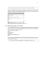
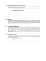
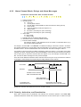
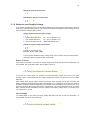
13 You can send the same commands to TC from HyperTerminal as you would send you’re your mobile phone. It takes about 5 seconds before the serial connection is established. If you are in Scandinavia, the font type must be changed to “Courier New” from the View menu. Otherwise, Scandinavian characters (ÅÄÖ) will not appear correctly on the screen. In addition, change “Line Delay” to 100ms from File / Properties / Settings / ASCII / Setup / Line Delay. This gives TC enough time to process each command after you hit enter. Picture HyperTerminal program that is available on Windows XP. 3.2.2 Uploading Settings from Text File You can upload a settings file to your TC by simply clicking “Send Text File” from your HyperTerminal. You can create the text file from scratch with Notepad or use a template file as the basis for your settings. This allows you to plan your settings carefully and send them to TC quickly in one session after the physical installation of the device is complete. An example setup file is shown below: #A33 3 #P1 +358xxnnnnnn #A10 Cottage #I2 2 0 1 60 Door open $Door closed #A33 0 The above settings have the following effect: the alarm message “Cottage IN2:+ Door open” is sent to the phone number in directory location P1 if the input 2 becomes activated. “Cottage IN2:- Door closed” is sent when the door is closed. The text file must always begin with #A33 3 and end with #A33 0 (see chapter 5.3.4). 14 3.2.3 Printing Settings through Serial Port All the TC’s settings can be printed in the HyperTerminal window or a file through serial port in the same format that can be used in sending them back to the TC. This helps the user in typing the basic settings and finding possible errors in the setup and fixing them. Printing settings through serial port P A R The hash sigh (#) is omitted from the command. The print-out is one long list of all parameters available for editing. You can copy selected commands and paste them into a text file that you can later upload to your TC. This command automatically adds #A33 3 at the beginning and #A33 0 at the end of the printed output. 3.2.4 Modem TC answers to incoming phone calls by default if they are made from allowed phone numbers. The incoming phone call is linked to the TC’s command interpreter if it is a data call (a call to the TC’s data number from fixed telephone network or GSM network). This enables you to send settings in a text file or give commands to your TC one at a time like in the direct data cable connection. 3.3 Testing Installation You should make sure that there is just your own phone number in the TC’s phone directory when you test the control circuits in order to avoid confusion among other users. You should test alarms from each sensor you have connected to the unit and send commands to test the outputs. However, before you start testing the installation of TC, you should print out an installation report from your TC. You should go though each alarm channel in the report and verify that the states of the control circuits are as intended (see chapter 3.3.1). 3.3.1 Installation Report After sensors have been installed, it is important to get feedback about whether the installation of TC was successful or not. Command #S5? returns information from which you can see whether the states of control circuits are as expected. Printing out installation report # S 5 ? If there are no alarms at the time of the query, the current state and the active state must be different from each other. 15 An example print-out: IN1 : 0 (1) IN2 : 0 (0) IN3 : 1 (0) IN4: 0 (1) IN5: 0 (1) IN9 : 0 (1) IN10 : 0 (1) IN11 : 1 (1) IN12 : 0 (1) IN13 : 0 (1) IN16 : 0 (1) IN17 : 0 (1) IN18 : 1 (1) Alarm channel one is in state 0 (open) and alarm state is 1. Alarm is off. Alarm channel two is in state 0 (open) and alarm state is 0. Alarm is on. Alarm channel three is in state 1 (closed) and alarm state is 0. Alarm is off. The temperature alarm is on or no sensor is connected to the input. The INx tells the number of the alarm channel and its logical state 1 = closed or 0 = open. The 1 or 0 in parenthesis is the alarm state. Note that the status is the actual state of the channel at the time of the query. In other words, activation and deactivation times have no effect on the print-out. Rule of interpretation If two adjacent numbers are equal, ones or zeroes, there is something wrong with the installation or the settings, or the alarm channel is currently on. 3.3.2 State Information The states of all outputs and alarm channels can be asked with single command #S1?. Asking the states of alarm channels and outputs # S 1 ? The above command returns information in the following format: I1:x I2:x ... I18:x O1:x x = the state of the alarm channel or output. 0 = off (open) and 1 = on (closed) The state is 1 when the control circuit is closed (current flows) and 0 when it is open. The active state and activation and deactivation times have no effect on the printed state. In outputs, state 1 means that the relay pulls and 0 means that the relay releases. 3.3.3 GSM Module Information The signal strength should be always checked after installing TC so that the operation is also guaranteed in poor GSM message traffic conditions (for example, leaves in trees). The signal level can be asked with command #?. The maximum value is 32. # ? The command returns: TC security:OFF Batt:12.1 T1:27.0 GSM signal:19 Active alarms: IN11 The signal strength level should be at least 10 to guarantee reliable GSM message traffic. 16 4. BASIC SETTINGS In this section we explain the settings of alarm channels and TC’s internal phone directory. After the basics we will explain how the operating mode can influence the sending of alarm messages. At the end of the chapter we will go through the basic settings of TC’s outputs and how macro commands can be used to make your life a bit easier. Alarm messages are formed in alarm channels. When there is an alarm the respective alarm channel immediately forms an alarm message and sends it to the defined users. You can also ask information about alarm channels at any time by text messages. You can command TC either by text messages or phone calls. A phone call from a trusted phone number triggers off a preset action. TC can execute commands on alarms as well. 4.1 Phone Directory TC requires that its internal phone directory contains at least one phone number in order to function normally. The phone directory is needed in sending alarm messages to the correct phone numbers, but also in recognizing legal users and their permission levels. There is room for twenty phone numbers in the directory and each number has a permission level (1 through 4). The default level for all users is 1. 4.1.1 Phone Numbers When the user wants to modify the settings of TC from his or her mobile phone, that mobile number must be stored in the TC’s internal phone directory. If that number does not exist in the directory and the user still wants to use his or her mobile phone, the unit must be switched to programming mode. The programming mode can be turned on by opening the device cover. The status light starts blinking as soon as the unit enters programming mode. In programming mode the unit accepts text messages from all phone numbers You can make setup changes though direct data cable when the unit is in programming mode. Adding a phone number to the directory # P x a a a a a a a b c d x = directory location (1 – 20) aa = the mobile number from which the device is intended to be used (the number must be given in the international format, for example, +358nnnnnn if you are in Finland. To find out your country code, send a text message to yourself and check the sender information). b = permission level (not required, default is 1) c = macro command number to be executed on phone call (not required) d = macro command number to be executed on data call (not required) If you give number 101 as parameter c, phone calls from this phone number can switch TC from normal to disable operating mode or vice versa (for example: #P3 +358xxxxxxx 1 101 0 , see chapter 4.4.3). If you give number 100 as parameter d, data calls from this phone number are routed directly to the TC’s command interpreter (for example: #P3 +358xxxxxxx 1 0 100). It is useful to have the number of the installer set in this manner so that he or she can make setup changes effortlessly though data connection. It is advisable to check the contents of the directory after any experiments so that no unwanted numbers remain in the directory. The following commands are used in displaying and editing the numbers in the directory. 17 Asking the contents of the directory # P ? This will print out the entire phone directory (P1...P20) Asking a single phone number # P x ? x = directory location 1 through 20 Asking a single phone number and its macro settings # P x ? ? x = directory location 1 through 20 This will print out the phone number and the macro commands Removing a phone number # P x x = directory location 1 through 20 This will clear the directory location x 4.1.2 Permission Levels Permission level (b) can be assigned to a phone number by adding a number 1 – 4 after the actual phone number. All phone numbers have unlimited rights (level 1) by default. All phone numbers can receive alarm messages regardless of the permission level. Level 1: All rights (this level is used if no parameter b is given in the command) Level 2: Can receive alarms and send commands to set relays on and off Level 3: Can only receive alarm messages Level 4: Can only receive alarm messages, but macro commands are also available 4.1.3 Wild-Card Characters It is possible to use so called wild-card characters in the phone directory. Wild-card characters enable the use of TC even if the phone number is given in its entirety. The following wild-card characters are available: ? matches any digit (exactly one) * matches zero or more digits For example, in command #P1 +35840123???? the last four (exactly four) numbers can be any digits. Whereas, command #P2 * 2 grants permission level 2 to all phone numbers. If wild-card characters are used in the directory, information security issues must be considered carefully. You should never grant permission level 1 to any number that has wild-card characters. It is recommended to use permission level 2 or 4 for these phone numbers. This prevents the modification of the unit’s settings from phone numbers that contain wild-card characters. If a phone number contains wild-card characters, no alarm messages are sent to the numbers matching the pattern. A hint: The company that performs the installation of your TC can leave their maintenance phone number or their TeleCont phone number in the unit’s phone directory. The maintenance worker is able to adjust the settings of the device without being physically present. You can block alarm messages from a phone number by appending the character * at the end of the phone number. 18 4.1.4 SMS Service Number TC automatically uses the SMS service number on the SIM card if there is one, otherwise the SMS service number must be explicitly programmed with command SMSC. If the unit is not responding to your text messages even when it should (see chapter 4.7.3), the SMS service number might be missing. You can find out the number from your subscription contract or by calling your operator. Setting the SMS Service Number S M S C a a a a a aaaaa = SMS Service Number 4.2 Alarm Channels TC sends all alarm messages and notifications through alarm channels. Each alarm channels reacts to the state of the corresponding input. Alarm channels are as follows: 1...5 9 10 11 12 13 16...18 control circuits (INPUT) 1...5 cover open unit restart power failure low battery timed messages temperature sensors T1...T3 4.2.1 Alarm Transfer Settings The following settings have effect on all alarm channels (global settings): Alarm expiration time (#A17 x y) The number of call retries (#A31 x) The phone call length (#A9 x y) The device name (#A10 xx) 19 4.2.2 Alarm Channel Mode, Delays and Alarm Messages Changing the channel mode, delay, and alarm message # I x a b c d y y y y y y y y y x = channel number 1-18 a = operating mode 0 = not in use 1 = one-way alarm channel 2 = two-way alarm channel (SMS’s are also sent when the alarm goes off) 3 = event counter 4 = control of operating mode (see chapter 4.4.1) 6 = delayed alarm 9 = like mode 1, but always on (24 h monitoring) 10 = like mode 2, but always on (24 h monitoring) b = active state 0 = open contact 1 = closed contact c = activation time in seconds (0-3000 seconds). d = deactivation time in seconds (0-3000 seconds). y = free form alarm message the maximum length is 160 characters minus the number of characters taken up by the command and its parameters. For example, command #I1 1 1 1 25 Alarm 1 modifies the settings of the alarm channel 1 as follows: the channel operates as a one-way alarm channel where alarm on is when the control circuit is closed. Activation time is 1 second and deactivation time is 25 seconds. The alarm message is “Alarm 1”. It is possible to remove the free form alarm message by entering a hyphen (-) in the place of the alarm message. The alarm message still has the fixed prefix INx: if it has not been removed and if the device has not been given a name with command A10 (see chapter 5.3.2). For example, command #I1 1 1 1 25 - removes the alarm message set in the previous example. There are certain differences between alarm channels and how they are set up; therefore the reader is encouraged to read carefully the programming and usage details for each channel. Circuit state (c) (d) Activation Activation time is reached Alarm is activated and sent Alarm deactivates Deactivation time starts (c) activation time (d) deactivation time Deactivation time is reached Activation time can now begin again Picture The activation and deactivation times for an alarm channel. 4.2.3 Polarity, Activation, and Deactivation Each alarm channel has five parameters that influence the channel’s operation. The alarm state parameter determines whether the channel is active when the control circuit is open or closed. The input 20 must be in the alarm state for as long as is defined by the activation time before any alarm messages are sent. After the alarm messages have been sent, the channel must be in the opposite state for as long as is determined by the deactivation time before new alarm can be sent. No new alarm messages are sent if the input returns back to the alarm state before the deactivation time has elapsed. The alarm channel’s event counter is incremented every time the state switches to active even if the channel is not set up as an event counter. The counter is incremented even in disable mode although no alarm messages will be sent. The activation and deactivation times are also available when the channels operate in event counting modes. 4.2.4 Two-Way Alarm TC can be programmed to send different text messages on activation and deactivation of an alarm channel. This can be accomplished by dividing the free form alarm message with separating character $ and setting the alarm channel to operating mode 2 (parameter a = 2 or 10). The first part of the message is sent on activation and the second part is sent on deactivation of the input. For example: #I1 2 1 1 25 Alarm 1 on$Alarm 1 off In the above example, the alarm channel 1 has been programmed to send an alarm message on deactivation as well (parameter a = 2). 4.2.5 Delayed Alarm This feature is meant to be used in the alarm channels that are placed in an area with security keypad (for example entrance hall) for controlling the TC’s operating mode. The alarm channel registers the active state quickly, but offers you the opportunity to stop the alarm message from being sent by switching TC to disable mode from the security keypad. The alarm message is postponed for the duration of the deactivation time if the operating mode of the alarm channel is 6. The length of the delay is the same as the deactivation time programmed for the alarm channel. For example: • • • • #I2 6 1 1 25 Alarm alarm channel two is in delayed alarm mode (= 6) alarm state is closed contact (alarm state = 1) alarm is registered after 1 second (activation time = 1) alarm message is sent after 25 seconds from activation (delay = 25) and alarm deactivates in 25 seconds 4.2.6 Channel Name Each alarm channel can be named. The name of the channel can be seen on the list of active alarms when asked with command #? (see chapter 4.4.5). Setting the channel name # I A x a a a a x = alarm channel number (1-18) a = name of the channel (default is Inx) 4.3 Sending Alarms This chapter explains the settings related to the sending of alarm messages. The sending procedure is controlled by the alarm channel settings, alarm transfer method, routing, and the phone directory. The alarm channel settings determine the actual alarm message and the alarm transfer method (phone call, text message, or both). Routing is used for selecting the phone numbers that will ultimately receive the alarm. By default, all alarm messages are routed to all phone numbers in the directory unless they contain so-called wild-card characters. Global settings can be used in determining what is contained in all of the alarm messages. For example, command #A10 sets the device name that is inserted in the beginning of each alarm message. 21 4.3.1 Message Recipients All alarm messages are sent to all phone numbers found in the TC’s internal phone directory by default. However, it is possible to route alarm messages to selected users with command #R. Each alarm channel can be routed up to ten different phone numbers. This feature allows you to determine the phone numbers and the calling order if so-called cyclic alarm transfer is being used. The cyclic alarm transfer method is used for reaching one person at a time from a list of people. General format for setting routing # R x y y y y x = alarm channel number (1-18) y = phone directory location (1-20, max 10 numbers) Routing all alarm channels at once # R * y y y y * = wild-card character that sets the routing to all channels 1-18 Removing routing from a channel # R x x = alarm channel number (1-18) Removing routing from all channels # R * * = wild-card character that corresponds to all channels 1 through 18 4.3.2 Transfer Method The alarm can be transferred as text messages, phone calls, or both. When phone calls are used, TC makes phone calls to users in addition to or instead of text messages. The alarm is acknowledged by answering to the phone call. TC will keep on calling until someone answers to at least one of the phone calls or until the alarm expires (see chapter 4.3.5). By default only text messages are sent. You can select the alarm transfer method with command #J. Commands #A17 and #A9 determine the number and the interval for call attempts, and the time used for waiting for anyone to pick it up and for how long the line is kept open. Setting the alarm transfer method # J x y x = alarm channel number 1-5, 9-13, and 16-18, wild-card character * applies to all channels y = transfer method: 0 = alarm messages are blocked out 1 = text message 2 = phone call 3 = text message and phone call 4 = text message and phone call to one phone number at a time (cyclic) T ext Message and Phone Call In alarm transfer methods 2 and 3, TC keeps on making phone calls relentlessly until everyone to whom the alarm was routed to has answered to the call. TC considers the call answered even when the phone call is answered by your answering machine. Notification messages from operators (such as “The number you are trying to call cannot be reached…”) are not considered as answered. When you are using transfer method 3, make sure that all phone numbers you have programmed to receive alarm messages can be reached! TC will keep on calling to the number 22 even if it is not a valid or a correct phone number. TC will also keep on trying to call to mobile phones until someone answers even if they are out of reach. This continued process of reaching people can slow down the operation of your TC for a while. The alarm expires after two hours by default. Cyclic GS M Short Me ssage and Phone Call In this transfer method (4) the alarm message is sent to one person at a time in the same order as the recipients’ phone numbers are kept in the phone directory (P1, P2 … P20). If the channel has been routed to particular phone numbers only, the order in which the messages are sent is determined by the routing order. The process of sending alarm messages is abandoned as soon as someone picks up the phone. The sequence is as follows: • • • • • • TC sends a text message to the first number in the directory (or in the routing list) TC makes a phone call to the same number if no one answers to the phone call, TC tries again (three times altogether) if someone answers to the phone call, no further calls are made to the remaining numbers if the third attempt to reach the person fails, TC moves on to the next phone number and starts the same procedure over again the task is abandoned when the end of list is reached An swering Machines TC waits for your answer for 30 seconds, but the time span can be changed with parameter y in command #A9. The connection is cut off after the specified period has elapsed. By setting the time span shorter than the time it takes for your answering machine to pick up a phone call removes the obvious problem with alarm condition getting acknowledged without you (the alarm is acknowledged by the answering machine and not you). For example, set the parameter y to 20 seconds if your answering machine answers to phone calls in 30 seconds (#A9 60 20). When you pick up the phone, TC sends two signals to alert you that connection has been established. 4.3.3 Timed Messages Alarm channel 13 allows TC to send messages at determined intervals. The programming of this channel slightly differs from the other alarm channels. The general pattern for setting the alarm channel 13 parameters # I 1 3 a b c d y y . . y a= 1 – feature is on 0 – feature is off b = Message contents. 4 = temperatures c = Interval between messages as minutes d = Offset (the time after which the first message is sent) as minutes (in reply message this indicates how long it is until the next message is sent) yy = Free form message given by the user, the contents of the parameter b are appended at the end of this If you ask the settings of this channel with command #I13?, the return message contains the programmed information except for variable d which signifies the time after which the next message will be sent out. For example, the below command will cause TC to send the first message after 60 minutes. Messages are then sent once a week at the same time: #I13 1 4 10080 60 Timed message Return message will be in the format: IN13:+ Timed message: T1:27.3C Living room T2:-15,5 Outdoors Alarm channel 13 can be routed to selected users just like in any other alarm channel. 23 4.3.4 Attempts in Cyclic Transfer The number of attempts your TC makes in trying to reach a person in the cyclic transfer mode can be reduced if it is important for anyone to know about the alarm without any delay. TC tries to call everyone at least 3 times by default, but this can be changed with command #A31. The number of attempts must be between 1 – 100. Setting the number of call attempts # A 3 1 x x = the number of attempts (1 – 100) 4.3.5 Alarm Expiration Time TC immediately starts counting time when it sends an alarm message or makes an alarm call. The alarm is discarded as obsolete if the phone calls were not answered within the specified expiration time. The expiration time and the gap between phone calls can be given with command #A17. The default expiration time is 120 minutes (2h). The alarm is also abandoned if text messages cannot be delivered because the GSM network is down, for example. Setting the expiration time and the gap between phone calls # A 1 7 x y x = expiration time as minutes (1 – 32000) y = the gap between alarm calls as minutes (1 – 10) This is a global parameter having an effect on all alarm channels. The minimum alarm expiration time is 1 minute and maximum is 32000 minutes (over 22 days). The maximum gap between phone calls is 10 minutes. 4.4 Blocking Alarm Messages If TC is in the normal operating mode, an alarm message is always sent when an alarm channel becomes active. These alarm messages can be blocked by setting TC to disable mode. Only channels set in modes 9 or 10 (24h monitoring) can send alarm messages in disable mode. There are three different ways to switch TC from normal to disable mode and vice versa: • • • By alarm (one of the control circuits is in operating mode 4) By text message (#ON / #OFF) By phone call Any of the above methods can be used in switching TC from disable mode back to normal mode regardless of what method was employed earlier. However, it is strongly recommended that only one method of changing operating mode is preferred over others for consistency. 4.4.1 Changing Operating Mode on Alarm You can control the operating mode of your TC from an alarm channel. This feature that involves an input controlling the operating mode of the device is sometimes called as shunting. When an alarm channel is shunted, the activation of that channel sets TC to disable mode. You can set this feature on with command #Ix parameter a = 4. For example, if you want to have the alarm channel 1 controlling the operating mode, send the following command to your TC: #I1 4 1 1 30 yyyy. The disable mode goes on when the alarm channel has been closed for one second. The unit returns back to the normal mode when the contact 1 has been open for at least 30 seconds. TC does not send a message when the disable mode is turned on or off. 24 When TC goes back to normal mode, it does not send any information about the state changes that occurred during the disable period. Those channels that are in active state during the transition from disable to normal mode will cause an alarm being sent. Commands for controlling outputs and other features work normally in disable mode. In disable mode the status light blinks twice. Alarm channels with operating mode 9 or 10 (24h monitoring) cannot be disabled. #Ix 9 or #Ix 10 Channels that have the above setting can be used, for example, for smoke detectors. It is certain that alarm messages are always sent from these channels regardless of the operating mode. 4.4.2 Changing Operating Mode with Text Messages TC can also be switched to disable mode with command #off. TC goes immediately into disable mode. On the other hand, command #on sets TC back to normal mode without any delay. Therefore, this command should not be sent when there are people in the monitored location. Setting disable mode on (alarms are off) # O F F Setting normal mode on (alarms are on) # O N As a response to both TC sends the following information: TC security: [ON/OFF] Batt: [12.1V] T1: [+25.4 Indoors] T2: [-12.2 Outdoors] 4.4.3 Changing Operating Mode with Phone Call TC’s operating mode can also be controlled by normal phone calls. You can select which phone numbers have this option enabled by setting parameter c to 101 when adding phone numbers in the TC’s internal phone directory (see chapters 4.1.1 and 4.7.2). Operation: To switch the monitoring on, all you have to do is to make a phone call to your TC. You will hear one or two beeps which lets you know in what mode TC will be switched to when YOU close the phone. One beep means that the monitoring is about to be switched on (normal mode) and a series of two beeps means that the monitoring is about to be switched off (disable mode). If you do not want to change the operating mode, just wait until TC closes the call. This behaviour is similar to the logic that is used in many electric locks in modern cars. A car’s turn indicators flash once when the locks are closed and twice when the locks are opened. Programming mode (status light blinks continuously) Normal mode (status light blinks once) Disable mode (status light blinks twice) Although the operating mode can be changed by several different means, it is recommended that only one method is used to avoid confusion about the current state of your TC. 4.4.4 Commands on Operating Mode Change You might want to have different settings for normal and disable modes. This can be achieved by setting TC to execute setup commands when operating mode is changed. For example, you might want to have lower temperature alarm limits when you are at home. 25 Setting relay and macro command # A 3 0 x y z x = relay used for signaling operating mode, this is always 0 (not used in TC543 model) y = macro command number (1-10) which is executed when normal mode is switched on z = macro command number (1-10) which is executed when disable mode is switched on The commands are cleared by setting x, y, and z to 0. Notice that there is no relay in TC543 model for operating mode. To set alarm limits for temperature sensors T2 and T3 according to operating mode: #A30 0 5 6 #M5 Away /#T2 10 25#T3 5 25/ #M6 Home /#T2 -5 25#T3 -5 25/ 4.4.5 Status Report Command #? returns a report that contains important status information. If the unit is in disable mode (OFF) and there are people in the monitored premises, there could be alarms in “Active alarms”. Asking status report # ? This command returns a status report containing the operating mode, battery voltage, temperatures, GSM signal strength, and active alarms: TC Security: ON Batt: 13.5 T1: +28.0 T2: +23.1 T3: -12.2 GSM signal: 26 Active alarms: 4.5 Temperature TC has three three temperature sensors (T1 – T3). These sensors use alarm channels 16 – 18. TC reads values from these sensors every 30 seconds. The sensors have a fixed 2 degree hysteresis (the difference in temperature between ON and OFF states) that prevents redundant alarm messages when the temperature fluctuates around the set alarm limit. Activation and deactivation times should also be set long enough to prevent unnecessary alarm messages. The maximum cable length for NTC temperature sensors is 50 meters (Telemic provides these cables). If the cables are over 5 meters long and/or they run alongside 230V cables, you have to use shielded cables and the covering must be grounded from the TC’s end of the cable. The minus of the power supply (10-13.8VDC) must also be grounded to the same spot. Working range for the T1 – T3 sensors is -50 … +70 degrees Celsius. The tolerance is ±0.5 between 0 … +30, outside that range the tolerance is ±2.0 degrees Celsius. Long cables (over 10 meters) can have an impact on the accuracy of measurements under poor conditions. 26 Table Analogue alarm channels. Sensor Alarm channel Physical location T1 16 Connector Temp 1 T2 17 Connector Temp 2 T3 18 Connector Temp 3 You can ask the temperatures from all sensors with command #T? or from a specific sensor with command #Tx?. Asking temperature # T ? An example print-out from TC with sensors T1 – T3: T1:+26.0 T2:+22.4 T3:+24.1 Asking the temperature alarm limits # T ? ? The first value is the measured temperature and the following values indicate the upper and lower alarm limits. If no sensor is connected to TC or if the cable is broken, the temperature will be -68.1. T1:+26.0 –10..30 T2:+25.5 –10..30 T3:+-68.1 –10..30 Setting alarm limits # T x a a b b y y y y y x = the number of the temperature sensor (1 - 3) aa = lower limit (default is -30) bb = upper limit (default is +50) yy = free form text, max 50 characters The limits must be given in whole numbers or with one decimal. A negative value can also be used. The returned confirmation message is the same as in asking the temperature, for example, T1: +23.5 – 10..30. An alarm message is sent when the temperature rises above or drops below the set limit values. Alarm messages are sent at -50 and +70 degrees by default. The alarm channel settings such as the routing of alarm messages (recipients), activation and deactivation times, one-way and two-way channel modes, and the free form alarm message can be programmed in the same manner as with other alarm channels. Example settings for sensors T1 and T2: #I16 2 1 10 10 Temperature alarm$Temperature OK #I17 1 1 10 10 Outside temperature below -25 The name of the temperature sensor will be displayed in the alarm message after the alarm text and temperature measurement. Example setup: #T1 10 30 Bedroom #I16 2 1 10 10 Temperature alarm$Temperature OK The unit sends the following message in the case of an alarm: 27 IN16:+ Temperature alarm T1:+9.8 Bedroom When asked with command #T1?: T1:+9,8 Bedroom In other words, temperature sensor works like a normally open contact. Alarm message is always sent when the temperature drops too low or climbs too high. Removing the free form text # T x a a b b - x = the number of the temperature sensor (1 - 3) aa = lower limit (default is -30) bb = upper limit (default is +50) 4.6 Outputs TC has 3 relays and 1 voltage output. You can set them closed, open, or you can pulse them for 0.11000000 seconds (i.e. for 11.5 days). The pulse command is particularly useful for opening electric locks and for resetting various kinds of devices. The pulse command can also be repeated automatically. Then the output will give a number of pulses that have a requested length. In a series of short pulses (less than 5 seconds) the timing is not exact in all cases. The length of the pulse can be off of the desired length by ± 1 second. 4.6.1 Relay/Voltage Output Settings Command #O is used for controlling the outputs in TC. The state of an output can be asked with command #Ox?, where x is the relay number. If the command parameter is some other value besides 1 or 0, the command is interpreted as a pulse command. The pulse command can be cancelled by opening or closing the output. You can assign a descriptive text to an output by sending a command such as #O1 Light on $Light off to TC. The text must not begin with a number or a hyphen. The hyphen clears the text. The text will be included in returned confirmation messages, in our example TC would return message O1:1 Light on. If there is an exclamation mark in the message, it means that you tried to set the output to a state in which it already was. Setting relay closed # O x 1 x = output number (1-3 = relays, 4 = voltage output) Setting a text to relay x # O x L i g h t o n $ L I g h t o f f x = output number (1-3 = relays, 4 = voltage output) Clearing the text from relay x # O x - x = output number (1-3 = relays, 4 = voltage output) 4.6.2 Pulsing You can pulse an output by giving a time limit (max 1 000 000 seconds, i.e. 11.5 days) instead of the ON/OFF information (1 or 0). If the relay was open before command, it is closed. If the relay was closed before the command, it will be opened for as long as was defined in the command. 28 If a new pulse command is received during the time TC is still executing a previous pulse command, the new time is added to the remaining time of the first pulse. The state of the output is not changed. For example, if a pulse command sets relay closed for two minutes, and after one minute another two-minute pulse command is received, the total length of the pulse is three minutes. The confirmation message contains the state of the relay and the remaining time of the pulse. No new confirmation message is sent when the relay returns to its original state. The pulse command can be cancelled by sending either command #Ox 0 or #Ox 1 (x is the relay number) depending on whether the user wants to leave the relay contact open or closed. Pulsing an output # O x y z x = output number (1-3 = relays, 4 = voltage output) y = the length of the ON or OFF pulse (do not use values 0 or 1 in pulsing) z = the number of pulses 1...1000000 (default is 1) For example, this feature can be used for beeping a local siren alarm differently depending on the alarm. 4.7 Phone Calls TC’s outputs can also be controlled by phone calls by default. Besides controlling outputs phone calls can also be used in controlling the operating mode. Remember to insert the caller’s phone number in the phone directory in the correct format. Determining how incoming phone calls are handled # A 8 x x = one of the following actions: 0 – the call is left unanswered 1 – the call is answered (default). 4 – the call is answered and data connection is established 9 – the call is left unanswered but the specified macro command is run If there is number ”100” in phone directory location along with the user’s phone number instead of a macro number, phone calls from that particular number will be connected to the TC’s command interpreter like data calls. It does not matter what you have specified with command #A8 x. 4.7.1 Maximum Phone Call Length You can set the maximum length for the phone call with parameter A9. The timeout applies to both answered and called phone calls. The counting starts from the moment the call is answered. Data connection to TC usually requires a longer phone call length. 29 Setting the timeout and the wait time # A 9 x y x = the phone call maximum length, default is 30 s. (1...3000 s.) y = the time to wait for an answer when TC is calling (1...3000 s.) 4.7.2 Macro Command on Phone Call You can execute a specified macro command with a phone call to the TC’s GSM or data number. A phone call to the data number can mean execution of a different command than a phone call to the GSM number. The data number on the TC’s SIM card is a service that enables data communication to the subscription. You can assign a macro command to a phone number by adding the macro number (1 – 10) after the permission level in command #P. Macro command is executed when a phone call is received. For example, #P3 +358xxxxxxx 1 5 6 sets macro number 5 to be executed on phone call and macro number 6 on data call. Asking the macro commands in the phone directory # P x ? ? x = directory location Example response: P3:+358xxxxxxx 1 5 6 This message means that the macro command 5 will be run when the user makes a call to the GSM number. If the user makes a phone call to the data number, macro command 6 will be executed. If you set the number 101 as the macro number for incoming phone calls: for example, #P3 +358xxxxxxx 1 101 0 A phone call from the specified number can switch the TC from normal to disable operating mode or vice versa (see chapter 4.4.3). If you set the number 100 as the macro number for incoming data calls: for example. #P3 +358xxxxxxx 1 0 100 Data calls from this number are directed to the command interpreter (see chapter 4.1.1). 4.7.3 Disabling Confirmation Messages The confirmation messages for output commands can be disabled with command #A7. For example, it might be necessary to disable confirmation messages in cases where your TC sends text messages to another TC. This prevents unnecessary text messages from being sent between devices. Confirmation messages are also pointless in situations where the user sees the action him or herself. For example, opening a gate. Enabling confirmation messages (default) # A 7 1 Disabling confirmation messages # A 7 0 30 4.8 Commands on Alarms You can program TC to execute commands when an alarm is activated or deactivated. This feature comes in handy, for example, in situations where an alarm from a humidity detector closes the water solenoid valve and sounds the siren. For example, setting #IN1 /#O1 2 10 pulses relay 1 when there is an alarm in channel 1. Use command #IFx to set a command for deactivation of alarm. Setting a command to be run on alarm # I N x / a a a x = alarm channel number (1-18) /a = command, must start with forward slash Setting a command to be run on deactivation of alarm # I F x / a a a x = alarm channel number (1-18) /a = command, must start with forward slash 4.8.1 Local Alarm Siren A local alarm siren can be programmed go on, for example, when the alarm channel 3 becomes active. The following example sets output 4 to give 15 pulses each 2 seconds long every time channel 3 is activated. #I3 1 1 1 10 Alarm /#O1 2 15 #IN3 /#O4 2 15 /#O2 1 Programming the alarm channel Commands #O4 2 15 ja #O2 1 are executed when there is an alarm TC always removes the slash from the command in the confirmation message. 4.9 Macro Commands It is possible to group several commands under one descriptive label called a macro command. This enables you to control your TC with the least effort. For example, if you have installed TC in your home, you can define two simple macro commands for controlling the TC’s operating mode depending whether you are at home or not. After you have specified the macro commands, you can use your TC with the following commands: #HOME or #AWAY Up to 10 different macro commands can be programmed into TC. Each command can be assigned a unique name, which can be 20 characters long at the most. These macro commands are caseinsensitive. You can group commands together as long as there are fewer than 50 characters. The command group must begin and end with character /. Macro commands present a powerful method for granting limited permission rights to users. Permission level 4 allows the user to receive alarm messages and to use specified macro commands only (see chapter 4.1.2). Programming a macro command # M x x = yyy = /#O1.. = y y y / # O 1 5 # T ? / macro command number (1...10) the name of the command (max 20 characters) the actual commands (max 50 characters) Do not combine many #M commands in one text message. Create only one macro command at a time. 31 For example, if the user has sent command #M1 Heating on /#O1 1#T?/ to his or her TC, it can be used in the following manner: Using the example macro command # H e a t i n g o n This command causes the relay 1 to pull. The received confirmation message will also contain the temperatures from the temperature sensors. Deleting macro command number x # M x - The name that you give to a macro command must not already exist in the TC’s instruction set. You cannot insert a macro command inside another macro command. 32 5. ADVANCED FEATURES The settings and commands that enable TC to be used in even greater variety of application domains are explained in this section. 5.1 Start-Up 5.1.1 Power Save Mode TC543 can be switched to power save mode, which means that it starts at regular intervals and stays on for the specified time only. The power save mode is intended to lengthen the uptime between battery recharges. Power save cycle (a) and operating time (b) are given in minutes. A shorter power save cycle than ten minutes does not reduce energy consumption because it consumes more energy to start-up the device than keep it running ten minutes. When TC enters power save mode it will switch off the status light. The light functions normally during operating times. When the unit goes from programming mode to power save mode, the status light is on for about ten seconds before going off as a sign of ’unusual setting’. Setting the power save cycle and operating time # A 3 6 a b a = power save cycle b = operating time 0 – 1140 minutes, 0 = feature is off 1 – 60 minutes When this feature is disabled with command #A36 0 0, TC responds with A36:0 1 (because the operating time cannot be zero). (a) Normal m ode Power save mode (a) power save cycle (b) operating tim e (b) If one of the TC’s control circuits goes into alarm state during power save cycle, TC sends an alarm message as soon as the next operating time starts. If the alarm condition remains even after that, no new alarm messages are sent at following operating times. Notice that the channel’s activating and deactivating times must be considerably shorter than the programmed operating time. Commands that are sent to the TC during the power save cycle are executed when the next operating time starts. However, remember that sent commands might expire prior to that. 5.1.2 Start-up on Alarm In power save mode TC can be programmed to start periodically with command #A36. TC can also be started in response to the input from control circuit one. 33 If your TC is in power save mode, all outgoing alarm messages experience about one minute delay compared to the behaviour in normal operating mode. This delay is caused by the start-up procedure TC goes through and the time needed in establishing GSM network connection. TC begins the start-up procedure as soon as it receives an alarm from input 1. However, even in this case, TC will be functional only during the operating time. The sensor connected to the control circuit one must be normally open contact and it must remain closed for at least as long as it takes for TC to start plus the activation time specified for the channel. This means that the contact must be closed for at least one whole minute, otherwise no alarm messages are sent even if TC starts. It should be noted that the deactivation time for the alarm channel 1 must have elapsed before TC can enter power save mode again. Therefore, one second activation and deactivation times are recommended for the alarm channel 1. Alarms that have been activated during the power save cycle will be sent when the input from the control circuit one causes TC to start. 5.1.3 Restart Message TC can send a restart message when the power is switched on although this feature is not enabled by default (a = 0). Enabling the restart message # I 1 0 a 1 c d y y . . y a, c, d, and yyy are the same as in other alarm channels 5.1.4 Start-Up Counter TC has an internal start-up counter that is incremented by one every time the power is switched on. The value of the counter can be asked with command #A6? and it can be reset to zero with command #A6 0 34 Asking the start-up counter value # A 6 ? Resetting the start-up counter to zero # A 6 0 5.1.5 Batteries and Supply Voltage TC is capable of measuring its own supply voltage. Measuring supply voltage is quite useful in situations where TC is used with battery back-up. You can receive an alarm message if the mains voltage is lost or when the battery voltage is getting too low. Setting the alarm limits for supply voltage # B x y z x = power failure alarm limit y = low voltage alarm limit z = limit for shutting TC down 8.0 – 30.0 V (default 12.7V) 8.0 – 30.0 V (default 11.5V) not in use (default 10.5V) Asking the supply voltage and the limits # B ? The above command returns: B:12.0V 12.7V 11.5V 10.5V The first value indicates the supply voltage at the moment and the rest three values are the alarm limit values programmed with command #B. Power Failure A power failure message is sent when the supply voltage drops below the value set with parameter x in command #B. The power failure alarm uses the alarm channel 11. # I 1 1 a 1 c d y y . . y a, c, d, and yyy are the same as in other alarm channels In the case of a power failure, TC appends the measured supply voltage at the end of the alarm message. Alarm is deactivated when the supply voltage rises at least 0.5V above the set low voltage alarm limit. Power failure alarm requires battery back-up so that the alarm message can be sent even when the battery voltage has dropped below the alarm limit (default 12.7V). Depending on the size and charge of the battery the alarm message is delayed by 5-20 minutes so that short black outs are filtered out. If you want to be informed about short power failures, the parameter x of command #B must be set so that the alarm message is sent immediately when the voltage of the battery charger drops, for example, from 13.5 volts down to 13 volts. Low Vo ltage Low voltage alarm is sent when the supply voltage falls below the limit set with the parameter y of command #B. This alarm uses channel 12. # I 1 2 a 1 c d y y . . y a, c, d, and yyy are same as in other alarm channels 35 The current supply voltage is appended at the end of the alarm message. TC exits alarm state when the voltage rises at least 0.5V above the set alarm limit. Shut Do wn L imit TC543 does not use the shut down limit that could be given with command #B (parameter z). This operation is accomplished by a fixed shut down limit. 5.1.6 Automatic Shut Down TC switches itself and the GSM module off if the supply voltage drops below 5V. TC will restart as soon as the voltage rises above 7V. 5.2 Event Counters Every alarm channel has its own counter. Every time an alarm channel is activated, the respective counter is stepped up by one. When an alarm channel is solely used for counting you have to set the channel to counting mode (3). In this particular mode, activations of the alarm channel do not cause alarms, but instead the counter is incremented by one on each activation. If activation and deactivation times are set to zero in counting mode, the counting speed is max 5 steps per second. The current counter values can be asked with command #C?. The values can also be retrieved counter by counter with command #C1?. A seed value can be given to each counter and it must be between 0 and the maximum value of 4 294 967 295. The default seed value is zero. Setting counting to start from 0 # C x 0 The counter will return back to zero after it has passed the maximum number 4 294 967 295. 5.2.1 Saving Counter Values Counter values are saved into non-volatile memory at regular intervals as determined with command #A3. The interval must be given as minutes, and it defaults to 30 minutes. The maximum value is 32000 minutes. Setting the saving interval to 60 minutes # A 3 6 0 5.3 GSM Traffic Settings 5.3.1 Removing Inx:+/- Prefix Every alarm message contains a +/- prefix by default depending on whether the alarm was activated or deactivated. Enabling prefix (default) # A 2 0 1 Disabling prefix # A 2 0 0 36 5.3.2 Device Name TC can include the name of the device in the beginning of all alarm and timed messages. This name can also be used in directing alarm messages to special services provided by the operator. These special services are different from operator to operator, and therefore their availability should be checked beforehand. For example, there could be services for directing alarm messages to your telefax machine. The prefix can be 20 characters long at the most. Naming the device # A 1 0 y y y yy = the device name Removing the name # A 1 0 - If you decide to combine several commands in one text message and you want to remove the device name, you have to place command #A10 last because otherwise the device name will be changed to whatever comes after #A10. 5.3.3 Text Messages Limit Command #A4 sets an upper limit for the number of text messages TC is allowed to send daily. This prevents text messages from being sent if, for example, the unit malfunctions for some reason. The default is 100 and the maximum is 32000 text messages in a day. Setting limit to text messages # A 4 1 0 0 TC will receive and execute commands normally even if the allowed daily quota of text messages has been consumed. However, TC will not send any confirmation messages in response to the commands it receives. Set the daily limit large enough if you are not getting any confirmation messages to your commands. Set the limit back to its original value after 24 hours when the text message counter has been reset. 5.3.4 Delay in Saving Parameters TC saves the given parameters into non-volatile memory immediately at the execution of a command. This default behaviour must be delayed before you can upload a setup file to your TC with data cable or data connection (see chapter 3.2.2). This can be accomplished by including command #A33 x on the first row in the setup file. The delay is removed with command #A33 0 on the last line of the setup file. # A 3 3 x X = the delay in saving parameters 0 – 5 min 5.3.5 Software Version 37 Asking TC’s software version # V ? This returns: V:TCnnn x.y.z Mmm dd yyyy ggggggg where TCnnn x.y.z Mmm dd yyyy ggggggg = TC model (TC543) = software version number = the release month = the release day = the release year = GSM modem type and software version An example response: V:TC543 5.1.8 Sep 09 2008 (TC45 02.02) 5.4 Serial Connection TC has a serial port which can be used for programming the device from a terminal program such as HyperTerminal. The serial connection does not use the so-called hand shaking signals. Only incoming and outgoing data and ground signals are used. Notice that the connector includes the unit’s supply voltage 10 – 13.8 VDC. Do not connect cables that you are unfamiliar with to the serial port (connector 1). 5.4.1 Terminal Connection You can program your TC by sending commands from you computer to your TC by connecting a data cable between them. The data transfer has the following settings: - bit rate: 9600 bits/s - data: 8 bits - no parity - no hand-shake Same commands work from command prompt as from mobile phones. For example: TC543> #T1? T1:+27.5 -30..+50 5.4.2 Data Calls TC can also be used through the GSM modem. This is possible if your own modem calls to the TC’s data number which establishes a data connection to the TC’s command interpreter. To establish a data connection you need to do the following: Enabling answering to an incoming call and data connection # A 8 4 When TC is used over data connection, a longer phone call duration setting than the default value of 30 seconds is required. 38 Setting the maximum length for the phone calls and wait time # A 9 x y x = maximum phone call length, defaults to 30 seconds (1...3000 s.) y = time to wait for an answer when TC calls (1...3000 s.) In addition, it should be remembered that the call must be made from a phone number that exists in the TC’s internal phone directory. If you have assigned 100 to a phone number as the macro command number, an incoming data call is switched directly to the TC’s command interpreter regardless of the parameter x (1 – 9) in command #A8. 39 6. TROUBLE SHOOTING If TC fails to function properly, please go through the steps in the table below. Problem: What to do The status light is off: Switch power on and wait for 30 seconds. TC does not receive text messages: SIM card’s PIN code must be disabled. Correct behaviour The light blinks. Note: wait 30 seconds after you have switched the unit on. The light flashes when sending a text message. Check TC’s phone number. TC receives text messages but it does not reply with confirmation messages: Insert the user’s phone number in the TC’s internal phone TC returns a confirmation message. directory. Only those text messages that are sent from trusted phone numbers are processed. Program your operator’s SMS service number to the device. TC returns a confirmation message. The maximum number of text messages TC is can send TC returns a confirmation message. daily has been consumed. See parameter #A4. The SIM card has a message limit. Your mobile phone’s memory is full of SMS messages. TC does not send alarm messages: Insert the recipient’s phone number in the phone directory. Alarm message is sent. The alarm channel has been routed to an empty directory Alarm message is sent. location (phone number is missing), or the phone number contains wild card characters. TC does not send alarm messages even if your phone number is in the directory: Verify that the alarm channel is activated. Ask the states of alarm channels with command #S5? No changes in relays: Insert your phone number in the phone directory. Only TC sends a confirmation message. commands from trusted phone numbers are executed. Verify that the syntax of the command is correct. Relay contact switches. Verify that the user has adequate permissions. Check that manual control for relay O1 is not on (red light). TC does not exit programming mode: Make sure that the phone directory is not empty. Relay contact switches. Operating mode changes. 40 7. COMMANDS SUMMARY AND DEFAULTS Command Default value #? Asking the TC’s operating mode You can append a question mark after any command if you want to know the current value instead of assigning it a new value #A3 x The interval for saving counter values x = time gap in minutes 30 minutes #A4 x The maximum number of text messages TC can send daily x = the number of messages per day 100 messages #A6 x Restart counter x = seed value 0 #A7 x Confirmation messages for relays x = 1 on, 0 off 1 (on) #A8 x #A9 x y Answering to incoming calls x = 0 off, 1 on, 3 operating mode change, 4 data connection, 9 #D without answer Phone call duration and waiting time x = maximum phone call length [s] y = time to wait for an answer [s] 1 (on) 30 seconds 30 seconds #A10 xx Device name (used in some operator services) xx = device name, max 20 characters (empty) #A17 x y Alarm message expiration time x = expiration time [min] y = time gap for phone calls [min] 240 min 2 min #A20 x Inx: prefix x = 0 disabled, 1 enabled #A30 x y z macro commands on operating mode change x = relay, always 0 (not used in TC543) y = macro command when switched to normal mode z = macro command when switched to disable mode 1 (enabled) 0 0 0 #A31 x The number of call attempts in one number in cyclic alarm transfer x = the number of attempts, 1-100 3 #A33 x Delaying parameter saving x = the delay 0..5 [min] 0 #A36 x y Power save settings x = power save cycle [min] y = operating time [min] 0 min 1 min #B x y z The alarm limit values for supply voltage x = power failure alarm limit [V] y = low voltage alarm limit [V] z = shut down limit [V] not in use 12,7 11,5 10,5 #Cx y Event counter x = alarm channel number 1..5, 9..13 or 16..18 y = counter value #Ix a b c d yy x= a= b= c= d= yy = Parameters for alarm channels 1-5 channel 1..5 operating mode alarm state, 0 normally closed, 1 normally open activation time 0..3000 [s] deactivation time 0..3000 [s] text 1 (one-way) 1 (normally open) 1 10 Alarm x 41 Command Default value #I9 a b c d yy Parameters for alarm channel 9 (cover) parameters like in other alarm channels #I10 a b c d yy Parameters for alarm channel 10 (Restart) parameters like in other alarm channels 0 1 10 10 Restart #I11 a b c d yy Parameters for alarm channel 11 (supply voltage) parameters like in other alarm channels 0 1 1 3000 Power failure #I12 a b c d yy Parameters for alarm channel 12 (low voltage) parameters like in other alarm channels 0 1 1 3000 Low voltage #I13 a b c d yy Parameters for alarm channel 13 (timed messages) a = 0 not in use, 1 in use b = the message contents 1,2,4,8,16,32,64 c = interval in minutes d = the offset before the first message is sent out in minutes yy = text 0 1 3600 0 Report #Ix a b c d yy Parameters for channels 16-18 (temperature) parameters like in other alarm channels 0 1 300 3000 Temp alarm #IAx aa Naming alarm channel x = channel number aa = name INx #INx y Setting command to be executed when there is an alarm x = channel number y = command starting with forward slash / #IFx y Setting command to be executed when alarm is deactivated x = channel number y = command starting with forward slash / #Jx y Channel specific alarm transfer method x = channel number or wild-card character * y = method: 0 = blocked 1 = text message 2 = phone call 3 = text message + phone call 4 = cyclic text message + phone call #Mx y z Macro commands (max 10) x = command number 1..10 y = name of the command z = the contents of the macro command started with a slash, max 50 characters #Ox 0|1 Opens or closes the output x = relay number 0 opens, 1 closes #Ox y z Pulses the output x = relay number y = 1..1000000 seconds z = the number of pulses 1..1000000 #Ox y$z Setting text to an output x = relay number y = the text when the output is on, must not begin with a number or a hyphen z = the text when the output is off (voluntary, leave $ out) #ON A switch from disable to normal operating mode #OFF A switch from normal to disable operating mode PAR Prints out all editable parameters to serial port. SMSC a Sets SMS Service number a = SMS Service number 1 (empty) 0 1 (empty) 42 Command Default value #P? Displays the phone directory (numbers 1–20) #P?? Displays the phone directory (numbers 1–20) and macro command numbers associated with each user #Px a b c d Inserts a phone number in the directory x = directory location 1..20 a = user’s phone number b = permission level c = the macro command number to be run on phone call d = the macro command number to be run on data call #Px (the directory is empty) 1 (empty) (empty) Clears the directory location x (x = 1..20) #Rx y y .. Routing (routes alarm messages to specified users) x = the alarm channel number or wild-card character * y = the directory location, max 10 (1-20) #S1? Displays the states of outputs and inputs #T? Displays temperature values #T?? Displays the temperatures and their alarm limits #V? Displays the TC’s software version number (empty) 43 8. TECHNICAL SPECIFICATIONS Dimensions: 146 x 211 x 52 mm Weight: ca 420 g Current consumption: at idle 1.5 - 20 mA / 12 V Supply voltage: 9 – 14.5 V Serial port: RJ-8 Maximum values for relays: power 72 W maximum 100 mA current 6 A voltage 12 V Maximum values for voltage output: power 9 W Current 750mA Voltage 12V Inputs: min. control circuit current 3,5mA/12V max control circuit resistance ca 30kohm / 12V Operating conditions: -20…+50 °C GSM module: Siemens TC65 SIM card: small, 3V Antenna: Quad-band (850/900/1800/1900), SMA connector The unit is not protected against water or any liquids. Note! Even though TC uses supply voltage from 9 to 14.5V, please, keep in mind that external devices (such as motion detectors) might not tolerate voltages this high. Technical specifications are subject to change without prior notice. The manufacturer does not guarantee the delivery of text messages. SMS services are provided by your telecommunications operator. 8.1 Control Circuit Connections 3k3 There are 5 inputs in TC543. The current is about 3.5mA with 12V. GND optocoupler F2 = 200mA fuse +VLB F2 IN 1 INPUTS 44 9. INDEX A Activation time ................................................... 19 Activation Time.................................................. 19 Active State ....................................................... 19 Alarm channel ..............................................10, 18 Alarm expiration time ......................................... 23 Alarm transfer method........................................ 21 Answering incoming calls ................................... 28 Answering machines.......................................... 22 Antenna............................................................. 43 Automatic shut down.......................................... 35 D deactivation time ................................................19 Deactivation Time...............................................19 Defaults .............................................................40 Delayed alarm ....................................................20 Device name ......................................................36 E Event counter .....................................................35 F B Battery voltage................................................... 34 Block diagram...................................................... 9 Blocking alarm messages .................................. 23 C Call attempts ..................................................... 23 Channel........................................................10, 18 Commands.......................................................... 7 #?.....Status report.......................................... 25 #A 3….Saving counter values......................... 35 #A 4….SMS limit ............................................ 36 #A 6….Start-up counter.................................. 33 #A 7….Confirmation messages....................... 29 #A 8….Answering phone calls ........................ 28 #A 9….Call length .......................................... 28 #A10..Device name........................................ 36 #A17..Alarm expiration time............................ 23 #A20..Inx+/- prefix.......................................... 35 #A31..Call attempts ........................................ 23 #B…..Supply voltage...................................... 34 #C…..Counters .............................................. 35 #I 1-8..Alarm Channels................................... 19 #I10..Restart .................................................. 33 #I12...Low Voltage ......................................... 34 #J…..Alarm transfer method ........................... 21 #O…..Relay control ........................................ 27 #OFF..To disable mode.................................. 24 #ON….To normal mode.................................. 24 #P…..Phone directory .................................... 16 #R…..Routing ................................................ 21 #S1….State information.................................. 15 #S2….GSM module information...................... 15 #S5….Installation report ................................. 14 #V…..Software version................................... 36 PAR…Printing parameters.............................. 14 Commands summary......................................... 40 Confirmation messages ..................................... 29 Control Circuit Current ....................................... 43 Control Circuit Resistance.................................. 43 Counters ........................................................... 35 Current Consumption......................................... 43 Fuse ..................................................................43 G GSM module ......................................................15 GSM Module ......................................................43 GSM traffic settings ............................................35 H Home.................................................................30 I Installation report................................................14 Interface...............................................................5 INx +/- prefix.......................................................35 L Low Voltage .......................................................34 M Macro command on operating mode change .......24 Macro Commands ..............................................16 Message recipients.............................................21 Modem connection .............................................14 N Non-volatile memory...........................................10 O OFF ...................................................................24 ON.....................................................................24 One-Way Alarm Channel ....................................19 Operating Mode..................................................19 Operating mode change .....................................29 Operating modes................................................11 Outputs ........................................................ 10, 27 P Phone call ..........................................................24 Phone call length................................................28 45 Phone directory ................................................. 16 Phone Directory................................................. 17 Phone numbers ................................................. 16 Power Failure .................................................... 34 Pulse counter .................................................... 35 Pulsing .............................................................. 27 R Restart message................................................ 33 Routing.............................................................. 21 S Security keypad ............................................20, 23 Separator $ ....................................................... 20 Serial connection ............................................... 37 Settings ........................................................12, 14 SIM Card........................................................... 43 Siren ................................................................. 30 SMS limit........................................................... 36 SMS Service Number......................................... 18 Software version................................................ 36 Start-up counter..................................................33 Start-up delay .....................................................5 State information ................................................15 Status light ...........................................................6 Status report ......................................................25 Supply Voltage ...................................................43 T TeleCont ..............................................................4 Telemic ..............................................................48 Temperature ......................................................25 Testing...............................................................14 Text messages limit............................................36 Timed messages ................................................10 Transfer method .................................................21 Trouble Shooting ................................................39 Two-way alarm...................................................20 Two-Way Alarm Channel ....................................19 V,W Wild-card characters...........................................17 GUARANTEE Telemic guarantees this TeleControl product for 12 months against material defects and flaws in manufacturing this product starting from the date of purchase. Defects are corrected with replacement parts, by fixing the old parts, or by providing a new equivalent product for the customer. Defects that are caused by natural deterioration over time, overloading, or by any other inappropriate use of this product are outside the sphere of this guarantee. Reclamations can be only accepted if the device is returned to the retailer or to the manufacturer unopened. PROOF OF COMPLIANCE TO STANDARDS The manufacturer guarantees that this product complies with the following standards: CC2 TC543: EMC, EN 301 489-1 v 1.4.1, EN 301 489-7 v 1.2.1, CISPR14 – 2 edition 1.1, 2001 Telemic Oy TC65: EMC, EN 301 489-1 v 1.4.1, EN 301 489-7 v 1.2.1, EN 301 511, IEC/EN 60950-1 47 NOTES Isoharjantie 6 Puh. +358 20 728 8740 71800 Siilinjärvi Fax +358 17 462 1212 FINLAND [email protected] http://www.telemic.net