1
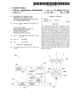
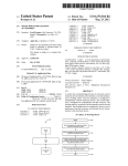
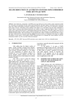
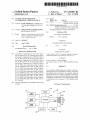
US007449847B2
(12) United States Patent
Schanberger et a].
(54)
US 7,449,847 B2
(10) Patent N0.:
(45) Date of Patent:
SYSTEMS AND METHODS FOR
SYNCHRONIZING LIGHTING EFFECTS
Nov. 11, 2008
(51)
Int. Cl.
H05B 37/00
(52)
US. Cl. ..................... .. 315/312; 315/317; 315/362;
(58)
Field of Classi?cation Search ............... .. 315/194,
(2006.01)
(75) Inventors: Eric K. Schanberger, Cambridge, MA
315/360; 362/227; 362/236
(US); Kevin J. DoWling, Westford, MA
315/291, 292, 294, 295, 312, 313, 317, 362,
315/360; 362/234, 227, 236; 323/235, 237
(Us)
(73) Assignee: Philips Solid-State Lighting Solutions,
See application ?le for complete search history.
Inc., Burlington, MA (U S)
(*)
Notice:
(56)
References Cited
Subject to any disclaimer, the term of this
patent is extended or adjusted under 35
U.S. PATENT DOCUMENTS
2,848,671 A
USC 154(b) by 874 days.
8/1958 McDonald
(21) Appl. N0.: 10/915,947
(22) Filed:
(65)
(Continued)
FOREIGN PATENT DOCUMENTS
Aug. 11, 2004
AU
Prior Publication Data
US 2005/0035728 A1
6 267 9
Feb. 17, 2005
(Continued)
Related US. Application Data
(63)
12/1996
OTHER PUBLICATIONS
Continuation of application No. 10/ 143,549, ?led on
May 10, 2002, noW Pat. No. 6,801,003, and a continu
*“LMl 17/LM317NLM317 3-Terminal Adjustable Regulator”,
National Semiconductor Corporation, May 1997, pp. 1-20.
ation-in-part of application No. 10/040,253, ?led on
(Continued)
Oct. 25, 2001, noW Pat. No. 6,781,329, and a continu
ation-in-part of application No. 10/040,291, ?led on
Primary ExamineriHaissa Philogene
Oct. 25, 2001, noW Pat. No. 6,936,978, and a continu
(74) Attorney, Agent, or FirmiWolf, Green?eld & Sacks,
ation-in-part of application No. 10/040,292, ?led on
Oct. 25, 2001, and a continuation-in-part of applica
RC.
tion No. 10/040,266, ?led on Oct. 25, 2001, noW Pat.
(57)
ABSTRACT
No. 6,774,584, and a continuation-in-part of applica
tion No. 10/045,629, ?led on Oct. 25, 2001, noW Pat.
No. 6,967,448, and a continuation-in-part of applica
tion No. 10/040,252, ?led on Oct. 25, 2001, noW Pat.
ing lighting effect generated by the lighting apparatus;
No. 6,869,204, and a continuation-in-part of applica
Wherein the processor is further con?gured to monitor an
operating poWer source; and Wherein the processor is further
tion No. 09/805,368, ?led on Mar. 13, 2001, noW Pat.
(60)
In one example, a lighting apparatus comprises a processor
Wherein the processor is con?gured to control a color-chang
No. 7,186,003, and a continuation-in-part of applica
con?gured to synchronize the color-changing lighting effect
tion No. 09/805,590, ?led on Mar. 13, 2001, noW Pat.
in coordination With a parameter of the operating poWer
No. 7,064,498.
Provisional application No. 60/290,101, ?led on May
10, 2001.
source.
42 Claims, 3 Drawing Sheets
/114
118
\
MEMORY
USER
INTERFACE
100
/
A/12a
102
104A
——
TIMING
CIRCUIT
LED
PROCESSOR
132
104B’ LED
—
LED
POWER
MONITOR
—RED
_
GREEN
—BLUE
1040
1J0
COM PORT
124
SENSOR
\122
US 7,449,847 B2
Page2
U.S. PATENT DOCUMENTS
2,909,097
3,104,815
3,318,185
3,561,719
3586936
3,601,621
3,643,088
3,746,918
3,818,216
3,832,503
3,845,291
3,858,086
3,909,670
3,924,120
3,958,885
3,967,170
3,974,637
4,001,571
4,054,814
4,082,395
4,096,349
4,241,295
4,272,689
4,273,999
4,298,869
4,305,117
4,317,071
4,329,625
4,367,464
4,388,567
4,388,589
4,392,187
A
A
A
A
A
A
A
A
A
A
A
A
A
A
A
A
A
A
A
A
A
A
A
A
A
A
A
A
A
A
A
A
4,394,716 A
4,396,871
4,420,711
4500796
4,564,889
4,616,298
A
A
A
A
A
10/1959
9/1963
5/1967
2/1971
6/1971
8/1971
2/1972
7/1973
6/1974
8/1974
10/1974
12/1974
9/1975
12/1975
5/1976
6/1976
8/1976
V1977
10/1977
4/1978
6/1978
12/1980
6/1981
6/1981
11/1981
12/1981
2/1982
5/1982
1/1983
6/1983
6/1983
7/1983
Alden et al.
Schultz
Kort
Grindle
McLeroy
Ritchie
Osteen eta1~
Druckeretal
Larraburu
Crane
Portyrata
Andersonetal.
Wakamatsu etal.
COX,IH
Stockinger et al.
MacDonald
Bergey etal
Martin
Fegleyetal
Donato et a1.
Donato
Williams, Jr.
Crosbyet 91
Pierpoint
Okuno
Evans
Murad
NishiZaWaetal.
Kurahashiet al.
Yamazaki eta1~
MolldremllrBornhorst
7/1983 Campagnaetal.
8/1983
12/1983
2/1985
1/1986
10/1986
Scheuermann
Takahashietal.
QuiI1
Bolson
Bolson
4,874,320
4,887,074
4,920,465
4,922,154
4,934,852
4,962,687
4,965,561
4,973,835
4,975,629
4,979,081
4,980,806
4,992,704
5,003,227
5,008,595
5,010,459
5,027,262
5,034,807
5,072,216
5,078,039
5,083,063
5,117,233
5,122,936
5,126,634
5,128,595
5,134,387
5,142,199
5,154,641
5,164,715
5,171,429
5,184,114
5,194,854
5,209,560
5,225,765
5,226,723
A
A
A
A
A
A
A
A
A
A
A
A
A
A
A
A
A
A
A
A
A
A
A
A
A
A
A
A
A
A
A
A
A
A
10/1989
12/1989
4/1990
5/1990
6/1990
10/1990
10/1990
11/1990
12/1990
12/1990
12/1990
2/1991
3/1991
4/1991
4/1991
6/1991
7/1991
12/1991
1/1992
1/1992
5/1992
6/1992
6/1992
7/1992
7/1992
g/1992
10/1992
11/1992
12/1992
2/1993
3/1993
5/1993
7/1993
7/1993
Freed etal.
Simon etal.
Sargent
Cacoub
Havel
Belliveau etal.
Havel
Kurosu etal.
Callahan etal.
Leach etal.
Tayloretal.
Stinson
Nilssen
Kazar
Tayloret 31‘
Freed
Von Kohom
Grange
Tulk etal.
Brooks
Hamosetal.
Guthrie
Johnson
Ham
Smith etal.
Elwell
McLaughlin
Kashiwabara etal.
Yasuo
Brown
Havel
Tayloretal.
Callahan etal.
Chen
5,254,910 A
10/1993 Yang
5,256,948
5,267,129
5,282,121
5,294,865
5,301,090
10/1993
11/1993
1/1994
3/1994
4/1994
A
A
A
A
A
Boldin etal.
Anderson
Bornhorstetal.
Haraden
Hed
4,617,498 A
10/1986 Ruppert
5,307,295 A
4/1994 Taylor etal.
4,622,881
4,625,152
4,633,161
4,635,052
4647217
4656398
4,668,895
11/1986
11/1986
12/1986
V1987
3/1987
4/1987
5/1987
5,319,301
5,329,431
5350977
5,357,170
5,371,618
5,374,876
5,388,357
6/1994 Callahan etal.
7/1994 Tayloretal.
A
A
A
A
A
A
A
Rand
Nakai
Callahan et al.
Aoike etal
Havel
Michael er 91Schneiter
A
A
A
A
A
A
A
9/1994
10/1994
12/1994
12/1994
2/1995
Hamamoto etal‘
Luchaco etal.
Tai etal.
Horibata etal.
Mama
4,675,575 A
6/1987 Smith etal. ............ .. 315/185S
5,402,702 A
4/1995
4,682,079 A
7/1987 Sanders er 91
5,404,282 A
4/1995 Klinke etal.
4,686,425
4,687,340
4,688,154
4,688,869
4,695,769
4,701,669
4,704,660
4,705,406
4,707,141
4,727,289
4,740,882
4,753,148
4,771,274
4,780,621
4,780,917
4,818,072
4,823,069
4,837,565
4,843,627
4,844,333
4,845,481
4,845,745
4,863,223
A
A
A
A
A
A
A
A
A
A
A
A
A
A
A
A
A
A
A
A
A
A
A
8/1987
8/1987
8/1987
8/1987
9/1987
10/1987
11/1987
11/1987
11/1987
2/1988
4/1988
6/1988
9/1988
10/1988
11/1988
4/1989
4/1989
6/1989
6/1989
7/1989
7/1989
7/1989
9/1989
Havel
Havel
Nilssen
Kelly
Schweickardt
Headet al.
Robbins
Havel
Havel
Uchida
Miller
Johnson
Havel
Bartleuccietal.
Hancock
Mohebban
Callahan et al.
White
Stebbins
Davis
Havel
Havel
Weissenbach etal.
5,406,176
5,410,328
5,412,284
5,412,552
5,420,482
5,421,059
5,432,408
5,436,535
5,455,490
5,461,188
5,463,280
5,465,144
5,489,827
5,491,402
5,504,395
5,530,322
5,539,624
5,545,950
5,561,346
5,569,371
5,575,459
5,575,554
5,592,051
A
A
A
A
A
A
A
A
A
A
A
A
A
A
A
A
A
A
A
A
A
A
A
4/1995
4/1995
5/1995
5/1995
5/1995
6/1995
7/1995
7/1995
10/1995
10/1995
10/1995
11/1995
2/1996
2/1996
4/1996
6/1996
7/1996
8/1996
10/1996
10/1996
11/1996
11/1996
1/1997
Ham
Sugden
Yoksza etal.
Moore etal.
Fernandes
Phares
Leffersplr‘
Matsuda etal.
Yang
Callahan etal.
Drago etal.
Johnson
Parkeretal.
Xia
Small
Johnson etal.
Ference etal.
Dougheny
Cho
Byme
Perling
Anderson
Guritz
Korkala
US 7,449,847 B2
Page 3
5,629,607
5,640,061
5,642,129
5,661,645
5,672,941
5,673,059
5,701,058
5,721,471
5,725,761
5,734,590
5,751,118
5,752,766
5,769,527
5,803,579
5,808,689
5,821,695
5,821,703
5,823,431
5,848,837
5,850,126
5,851,063
5,852,658
RE36,030
5,859,508
5,896,010
5,912,653
5,924,784
5,927,845
5,946,209
5,952,680
5,959,547
5,963,185
5,974,553
6,002,216
6,008,783
6,016,038
6,018,237
6,021,960
6,025,550
6,030,108
6,031,343
6,036,333
6,068,383
6,072,280
6,095,661
6,097,352
6,127,783
6,132,072
6,135,604
6,150,774
6,166,496
6,175,201
6,183,086
6,184,628
6,196,471
6,211,626
6,215,409
6,250,774
6,252,358
6,292,901
6,340,868
6,379,025
5/1997
6/1997
6/1997
8/1997
9/1997
9/1997
12/1997
2/1998
3/1998
3/1998
5/1998
5/1998
6/1998
9/1998
9/1998
10/1998
10/1998
10/1998
12/1998
12/1998
12/1998
12/1998
1/1999
1/1999
4/1999
6/1999
7/1999
7/1999
8/1999
9/1999
9/1999
10/1999
10/1999
12/1999
12/1999
1/2000
1/2000
2/2000
2/2000
2/2000
2/2000
3/2000
5/2000
6/2000
8/2000
8/2000
10/2000
10/2000
10/2000
11/2000
12/2000
1/2001
2/2001
2/2001
3/2001
4/2001
4/2001
6/2001
6/2001
9/2001
1/2002
4/2002
Callahan et al.
Bornhorst et al.
6,445,139
6,459,919
6,469,457
6,495,964
Zavracky et al.
Hochstein
Callahan et al.
Zavracky et al.
Roth
Begemann et al.
6,801,003 B2 *
6,811,286 B2
2001/0033488 A1
Bailey et al.
Taylor et al.
Turnbull et al.
Small
Vilanilam et al.
Callahan et al.
Pierce
Gustafson
Kanbar
Doughty et al.
Knight et al.
Nadeau
Ge et al.
MikolajcZak et al.
Fitch
Chliwnyj et al.
Gustafson et al.
Eckel et al.
Strite
Tubel et al.
Havel
Gandar
Mateescu
Kitagawa et al.
Mueller et al.
Havel
Kehat
Kato
Ishiharada et al.
Recknagel et al.
CA
DE
EP
EP
EP
EP
EP
EP
EP
EP
EP
FR
GB
GB
GB
GB
GB
GB
GB
JP
JP
JP
JP
JP
JP
JP
JP
W0
W0
W0
W0
Zavracky et al.
Pashley et al.
Turnbull et al.
Lin
Mueller et al.
Marshall et al.
Lys et al.
Callahan
Muthu et al.
10/2004
Schanberger et al. ..... .. 315/291
11/2004 Mateescu et al.
10/2001 Chliwnyj et al.
2 178 432
19942177
0495305
0534710
0752632
0752632
0823812
0935234
0942631
1020352
1113215
8817359
1439924
2029135
2045098
2135536
1439924
2176042
2355841
02-007393
06043830
7-39120
07-282614
8-106264
08180978
9 320766
3076701
WO 89/05086
WO 94/18809
WO 95/13498
WO 96/41098
Spiller
Robertson et al.
Allen
Lebens et al.
9/2002
10/2002
10/2002
12/2002
FOREIGN PATENT DOCUMENTS
Phillips
Tebbe
Mortimer
B1
B1
B2
B1
A1
A2
B1
A2
A3
A2
A1
A2
A2
A2
A
A
A
A
A
A
12/1996
3/2001
7/1992
1/1996
1/1997
8/1997
2/1998
8/1999
9/1999
7/2000
7/2001
12/1998
6/1976
3/1980
10/1980
8/1984
6/1986
12/1986
5/2001
1/1990
2/1994
7/1995
10/1995
4/1996
7/1996
12/1997
1/2001
6/1989
8/1994
5/1995
12/1996
OTHER PUBLICATIONS
*“DS96177 RS-485 / RS-422 Differential Bus Repeater”, National
Semiconductor Corporation, Feb. 1996, pp. 1-8.
*“DS2003 / DA9667 / DS2004 High Current /Voltage Darlington
Drivers”, National Semiconductor Corporation, Dec. 1995, pp. 1-8.
*“LM140A / LM140 / LM340A / LM7800C Series 3iTerminal
Positive Regulators”, National Semiconductor Corporation, Jan.
1995, pp. 1-14.
Lys et al.
Sid
Neubert
Excerpts (Cover, Title page, pp. ii through iii and 2-13 through 2-14).
Ruthenberg
Ruthenberg
2000, Excerpts (Cover, pp. 7,92 through 102).
Lys et al.
Blach
Begemann et al.
Xydis et al.
Lys et al.
Lys et al.
Artistic License, Miscellaneous Documents (2 sheets Feb. 1995 and
NeWnes’s Dictionary of Electronics, Fourth Edition, S.W. Amos, et
al., Preface to First Edition, pp. 278-279.
Mateescu et al.
* cited by examiner
*High End Systems, Inc., Trackspot User Manual, Aug. 1997,
*Artistic License, AL4000 DMX512 Processors, Revision 3.4, Jun.
Artistic License, Miscellaneous Drawings (3 sheets) Jan. 12, 1995.
Apr. 1996).
“http://WWW.luminus.cx/projects/chaser”, (Nov. 13, 2000), pp. 1-16.
US. Patent
200 \
Nov. 11,2008
Sheet 2 of3
US 7,449,847 B2
US. Patent
Nov. 11,2008
Sheet 3 of3
US 7,449,847 B2
flr/p. AulHIl//
/
//\.
/I
i
i
/
n...j4..
|A
200
200
FIG. 4
US 7,449,847 B2
1
2
SYSTEMS AND METHODS FOR
SYNCHRONIZING LIGHTING EFFECTS
SUMMARY OF THE INVENTION
An embodiment of the present invention is a lighting appa
ratus. The lighting apparatus comprises a processor Wherein
the processor is con?gured to control a color-changing light
CROSS REFERENCES TO RELATED
APPLICATION
ing effect generated by the lighting apparatus; Wherein the
This application claims the bene?t under 35 U.S.C. §120 as
processor is further con?gured to monitor an operating poWer
source; and Wherein the processor is further con?gured to
a continuation (CON) of US. Non-provisional application
Ser. No. 10/143,549, ?led May 10, 2002 now US. Pat. No.
synchroniZe the color-changing lighting effect in coordina
6,801,003, entitled “Systems and Methods for Synchronizing
Lighting Effects.”
tion With a parameter of the operating poWer source.
An embodiment of the present invention is a lighting appa
Ser. No. 10/143,549 in turn claims the bene?t of US.
ratus. The lighting apparatus comprises a processor Wherein
provisional application Ser. No. 60/290,101, ?led May 10,
the processor is con?gured to execute a program to control a
lighting effect generated by the lighting apparatus; the pro
2001, entitled “SYSTEMS AND METHODS FOR SYN
CHRONIZING ILLUMINATION SYSTEMS.”
Ser. No. 10/ 143,549 also claims the bene?t under 35
U.S.C. §120 as a continuation-in-part (CIP) of the following
cessor is further con?gured to monitor an operating poWer
source; and the processor is further con?gured to synchroniZe
the execution of the program in coordination With a parameter
of the operating poWer source.
An embodiment of the present invention is a lighting appa
US. non-provisional applications:
Ser. No. 10/040,253, ?led Oct. 25, 2001 now US. Pat. No.
6,781,329, entitled METHODS AND APPARATUS FOR
20
ratus. The lighting apparatus comprises a processor Wherein
the processor is con?gured to control a lighting effect gener
ated by the lighting apparatus; the processor is further con
?gured to monitor a parameter of an operating poWer source;
and the processor is further con?gured to synchroniZe the
25
lighting effect in coordination With the parameter.
ILLUMINATION OF LIQUIDS;
Ser. No. 10/040,291, ?led Oct. 25, 2001 now US. Pat. No.
6,936,978, entitled METHODS AND APPARATUS FOR
REMOTELY CONTROLLED ILLUMINATION OF LIQ
UIDS;
An embodiment of the present invention is a method of
Ser. No. 10/040,292, ?led Oct. 25, 2001, entitled LIGHT
SOURCES FOR ILLUMINATION OF LIQUIDS;
Ser. No. 10/040,266, ?led Oct. 25, 2001 now US. Pat. No.
6,774,584, entitled METHODS AND APPARATUS FOR
SENSOR RESPONSIVE ILLUMINATION OF LIQUIDS;
Ser. No. 10/045,629, ?led Oct. 25, 2001 now US. Pat. No.
6,967,448, entitled METHODS AND APPARATUS FOR
generating a lighting effect. The method comprises the steps
of: providing an lighting apparatus; providing poWer to the
lighting apparatus; causing the lighting apparatus to monitor
30
apparatus; and causing the lighting apparatus to generate a
color changing lighting effect in sync With the at least one
parameter.
CONTROLLING ILLUMINATION;
Ser. No. 10/040,252, ?led Oct. 25, 2001 now US. Pat. No.
6,869,204, entitled LIGHT FIXTURES FOR ILLUMINA
35
An embodiment of the present invention is a lighting appa
ratus. The lighting apparatus comprises a processor Wherein
the processor is con?gured to execute a program to control a
TION OF LIQUIDS;
lighting effect generated by the lighting apparatus; the pro
Ser. No. 09/805,368, ?led Mar. 13, 2001 now US. Pat. No.
7,186,003, entitled LIGHT-EMITTING DIODE BASED
PRODUCTS; and
at least one parameter of the poWer provided to the lighting
40
Ser. No. 09/805,590, ?led Mar. 13,2001noW US. Pat. No.
7,064,498, entitled LIGHT-EMITTING DIODE BASED
cessor is further con?gured to receive a synchroniZing signal
from an external source; and the processor is further con?g
ured to synchroniZe the execution of the program in coordi
nation the synchroniZing signal.
PRODUCTS.
Each of the foregoing applications is hereby incorporated
herein by reference.
BRIEF DESCRIPTION OF THE FIGURES
45
FIELD OF THE INVENTION
The invention generally relates to light emitting diode
devices. More particularly, various embodiments of the
50
invention relate to illumination systems and methods for con
trolling such systems.
DESCRIPTION OF RELATED ART
55
There are specialiZed lighting systems that can be arranged
to provide color-changing lighting effects (eg color-chang
ing LED lighting systems or lighting systems With moving
The folloWing ?gures depict certain illustrative embodi
ments of the invention in Which like reference numerals refer
to like elements. These depicted embodiments are to be
understood as illustrative of the invention and not as limiting
in any Way.
FIG. 1 is a lighting apparatus according to the principles of
the present invention.
FIG. 2 illustrates an environment With lights according to
the principles of the present invention.
FIG. 3 illustrates an environment With lights according to
the principles of the present invention.
FIG. 4 illustrates an environment With lights according to
the principles of the present invention.
?lters or the like). Some such systems may be arranged in a
network con?gurations to generate coordinated lighting
effects. Lighting systems to generate coordinated lighting
60
The description beloW pertains to several illustrative
embodiments of the invention. Although many variations of
the invention may be envisioned by one skilled in the art, such
effects typically are popular in theater lighting and are also
becoming popular in other venues Where color changing
lighting effects are desirable. There are also color changing
lighting systems that are not associated With a network. Such
systems may include a number of lighting components that
may not be synchronized.
DETAILED DESCRIPTION
65
variations and improvements are intended to fall Within the
compass of this disclosure. Thus, the scope of the invention is
not to be limited in any Way by the disclosure beloW.
US 7,449,847 B2
3
4
Applicants have recognized and appreciated that there are
lighting applications in Which it may be desirable to coordi
ducing the effects in coordination With one another. Each of
the lighting systems may be generating a color Wash and the
nate the light output of multiple light sources that are not
necessarily con?gured in a netWork environment, as dis
cussed above. For example, it may be desirable to change all
remain in sync.
Another aspect of the present invention is an adjustable
color Wash effects from each of the lighting systems Will
the non-networked lights in a room or section of a room
timing circuit con?gured to change the timing of the genera
simultaneously so they are the same color at any one time but
tion of a lighting effect. In an embodiment, a timing circuit is
continually changing at a particular rate. Such an effect is
termed a “color Wash.” A color Wash might provide the fol
loWing sequence: red to orange to yelloW to green to blue to
orange and so on. Upon poWer-up, all the lights may initiate
the same state and the color Wash may appear synchronized.
If the color Wash speed is relatively sloW and the duration of
the cycle through the Wash is signi?cant, say a minute or
more, than the lights Will appear synchronized. But the
appearance is deceiving; there is no coordinating signal to
associated With a user interface such that a user can adjust the
timing of the generation of the lighting effect. For example,
several lighting systems may be associated With a poWer
source in a hallWay and each system may be set to a color
Wash effect. A user may adjust the timing of each of the
several systems to begin the execution of the lighting program
at a different time. The systems further doWn the hallWay may
be adjusted With a increasing delay such that the color Wash is
offset by certain amounts as the systems progress doWn the
hall. This Would result in a staggered effect, and in the case of
the staggered color Wash, a Washing rainboW doWn the hall
insure that the lights are, in fact, synchronized. The scheme
depends on the independent internal clocks staying in syn
20
Way. The timing could be arranged such that, for example, as
the ?rst lighting system cycles through blue into the next
25
color, the second system is cycling into blue. In an embodi
ment, the timing circuit may be provided With a substantially
continuous variable timing. In an embodiment, the timing
circuit may be provided With predetermined offsets of time
periods. Another example of a useful or desirable lighting
chronization and some event to start the effect, typically
poWer-up. Over time, the lights become out of phase With one
another and may no longer be synchronous. This is due to
slight variations over time, or drift, in the timing elements
common to all microprocessor circuits. These elements are
subject to variation because of the manufacturing process,
temperature variations etc. This drift, While sloW, is observ
able, and if the timing of the events controlled by the micro
effect that appears to pass from one lighting system to another
is a “chasing effect.” The chasing effect may appear to pass a
red light, for example, from a ?rst light to a second light to a
processor is rapid, it Will be evident Within tens of minutes or
certainly Within hours.
It should be appreciated that the above discussion of a
“color-Wash” lighting effect is for purposes of illustration
only, and that any of a variety of lighting effects may be
subject to similar synchronization issues. In vieW of the fore
30
going, Applicants have recognized and appreciated that it
Would be useful to provide lighting systems that can produce
synchronized lighting effects Without necessarily requiring a
netWork con?guration.
35
Accordingly, one aspect of the present invention is directed
systems and appear to be chasing the red light doWn a hall
Way, for example. In an embodiment, there may be a delay
to a lighting system that generates synchronized lighting
effects. In an embodiment, the lighting system monitors a
poWer source and synchronizes the lighting effects it gener
40
ates With a parameter of the poWer source. For example, the
lighting system may be attached to anA.C. poWer source and
may be used to generate the delay. The adjustment may be
45
50
may include one or more pre-programmed lighting effects
and a user interface for selecting one of the lighting effects.
Once the effect has been selected, the processor may execute
the program in coordination With a parameter of the poWer
55
source, causing a synchronized generation of the lighting
effects With the poWer source such that each of them is pro
poWer distribution system and several outlets supplied by
another phase of the AC. poWer distribution. The timing
circuit may be con?gured to be adjusted to compensate for the
phase difference such that the timing of the lighting effects
nizing the generation of lighting effect, such as a color chang
present invention generates lighting effects in coordination
be monitoring and coordinating the execution oftheir lighting
In an embodiment, an adjustable timing circuit may be
used to compensate for phase or frequency differences in a
given installation. For example, a room may be provided With
several electrical outlets supplied by one phase of an AC.
from lighting systems on the tWo phases are in sync.
While many of the embodiments herein teach of synchro
effect.
In one embodiment, a lighting system according to the
With a reference value. In one aspect, several such lighting
systems may be associated With a poWer source and all of the
systems Would be coordinated With one another because they
Would be coordinated With a parameter of the poWer source.
For example, you could attach several lighting systems to a
poWer source in a hallWay. Each of the lighting systems may
used to create the appearance that it took time to pass the red
lighting effect from a ?rst lighting system to a second and so
on.
of the poWer source or other randomly, periodically or other
Wise occurring parameter of the poWer source. This provides
for a synchronized lighting effect Without the need for net
Work communication. In an embodiment, the lighting system
imposed betWeen tWo lighting systems generating the effect.
For example, the program the lighting system is executing
may generate the delay period such that it does not generate
the red lighting effect until tWo seconds or a number of cycles
have passed. In another embodiment, a user adjustable timer
the lighting system may include a processor con?gured to
execute a lighting program. The timing of the program execu
tion may be coordinated With the frequency of the AC. poWer,
voltage or current. In an embodiment, the lighting system
may coordinate the lighting effect With a transient parameter
third. The timing of the generation of the red light may be
synchronized via systems according to the principles of the
present invention. So, a ?rst light may generate red light for a
predetermined time, ?ve seconds or a number of sync cycles
or the like. During this period, a second light may be off (i.e.
generating no effect) and folloWing this period, the second
light may generate the red lighting effect for the same period.
This effect may appear to propagate through many lighting
ing lighting effect, in an embodiment, the synchronization
60
function may be used to synchronize other events as Well. For
example, the lighting system may be con?gured to generate a
lighting effect at a given time and the time may be measured
using the synchronization signal. For example, there may be
65
several lighting systems in an installation and they may be
generating a continuously color changing effect in sync. The
several lighting systems may be programmed to change
modes, into a ?xed color mode for example, after they have
US 7,449,847 B2
5
6
generated the color changing effect for a period of ?ve min
utes. A synchronizing signal may be generated from the peak,
Where it Would be desirable. Many such lighting systems may
be netWorked together to form large netWorked lighting appli
zero crossing, or some other parameter of anA.C. poWer line
cations.
In an embodiment the LEDs 104 and or other components
and this signal may be used to calculate, or measure, the ?ve
comprising a lighting system 100 may be arranged in a hous
minute period. In this example, the several lighting systems
Would stop the generation of the color changing effect and go
ing. The housing may be con?gured to provide illumination
into the ?xed color mode at the same time because they Would
to an area and may be arranged to provide linear lighting
patterns, circular lighting patterns, rectangular, square, or
be generating the lighting effect in sync With a synchroniza
tion signal. In an embodiment, the timing, or synchronization,
of events may be made in absolute time (eg knoWing or
measuring the frequency and generating a real time clock or
knoWn rate clock pulse) or the timing may be in relative
other lighting patterns Within a space or environment. For
example, a linear arrangement may be provided at the upper
edge of a Wall along the Wall-ceiling interface and the light
may be projected doWn the Wall or along the ceiling to gen
erate certain lighting effects. In an embodiment, the intensity
of the generated light may be suf?cient to provide a surface
(eg a Wall) With enough light that the lighting effects can be
measures (e. g. not knoWing the real time occurrence of a
parameter but synchronizing to the generation of the occur
rence).
seen in general ambient lighting conditions. In an embodi
ment, such a housed lighting system may be used as a direct
There are many environments Where a system according to
the present invention may be used such as indoor lighting,
outdoor lighting, landscape lighting, pool lighting, spa light
ing, accent lighting, general lighting, WalkWay lighting, path
Way lighting, guidance lighting systems, decorative lighting,
vieW lighting system. For example, such a housed lighting
system may be mounted on the exterior of a building Where an
20
informative lighting, or any other area or situation Where
synchronized lighting effects are desirable or useful.
FIG. 1 illustrates a lighting system 100 according to the
principles of the present invention. Lighting system 100 may
25
include one or more LEDs 104A, 104B, and 104C. The LEDs
104 may be provided on a platform 128. Where more than one
mounted as desired in the particular application. In an
embodiment, the housing and lighting system 100 may be
LED is used in the lighting system 100, the LEDs may be
mounted on the platform 128 such that light projected from
the LEDs is mixed to project a mixed color. In an embodi
arranged as a device that plugs into a standard Wall electrical
outlet. The system may be arranged to project light into the
30
environment. In an embodiment, the system is arranged to
project light onto a Wall, ?oor, ceiling or other portion of the
environment. In an embodiment, the lighting system is con
?gured to project light into a diffusing optic such that the
optic appears to gloW in the color projected. The color may be
35
a mixed, ?ltered or otherWise altered color of light and the
ment, the LEDs 104A, 104B, and 104C may produce differ
ent colors (e.g. 104A red, 104B green, and 104C blue). The
lighting system 100 may also include a processor 102
Wherein the processor 102 may independently control the
output of the LEDs 104A, 104B, and 104C. The processor
may generate control signals to run the LEDs such as pulse
system may be con?gured to change the color of the light
projected onto the optic.
modulated signals, pulse Width modulated signals (PWM),
pulse amplitude modulated signals, analog control signals or
The lighting system 100 may also include memory 114
other control signals to vary the output of the LEDs. In an
embodiment, the processor may control other circuitry to
control the output of the LEDs. The LEDs may be provided in
observer may vieW the lighted section of the lighting system
directly. The housing may include optics such that the light
from the LED(s) 104 is projected through the optics. This may
aid in the mixing, redirecting or otherWise changing the light
patters generated by the LEDs. The LED(s) 104 may be
arranged Within the housing, on the housing or otherWise
Wherein one or more lighting programs and or data may be
40
stored. The lighting system 100 may also include a user
interface 118 used to change and or select the lighting effects
strings of more than one LED that are controlled as a group
generated by the lighting system 100. The communication
and the processor 102 may control more than one string of
betWeen the user interface and the processor may be accom
LEDs. A person With ordinary skill in the art Would appreciate
that there are many systems and methods that could be used to
45
operate the LED(s) and or LED string(s) and the present
such that the processor executes a lighting program that Was
stored in memory. The user interface may be con?gured to
select a program or lighting effect from memory 114 such that
invention encompasses such systems and methods. In an
embodiment, a processor may be con?gured to control an
illumination source that is not an LED. For example, the
system may contain an incandescent, halogen, ?uorescent,
high intensity discharge, metal halide, or other illumination
the processor 102 can execute the selected program.
50
referred to hereinafter as sensors). The sensors may be asso
ciated With the processor 102 through Wired or Wireless trans
mission systems. Much like the user interface and netWork
55
light projected by the lighting system.
60
processor 102 may control the output of the LEDs such that
the light from tWo or more of the LEDs combine to produce a
mixed colored light. Such a lighting system may be used in a
variety of applications including displays, room illumination,
decorative illumination, special effects illumination, direct
illumination, indirect illumination or any other application
control systems, the sensor(s) may provide signals to the
processor and the processor may respond by selecting neW
LED control signals from memory 114, modifying LED con
trol signals, generating control signals, or otherWise change
the output of the LED(s). In an embodiment, the lighting
A lighting system 100 according to the principles of the
present invention may generate a range of colors Within a
color spectrum. For example, the lighting system 100 may be
provided With a plurality of LEDs (e.g. 104A-C) and the
The lighting system 100 may also include sensors and or
transducers and or other signal generators (collectively
source and the processor may be con?gured to control the
intensity or other aspect of the illumination source. In an
embodiment, the processor may be con?gured to control a
?lter, ?lter Wheel, a ?lter including more than one color,
movable ?lters, multiple ?lters or the like in order to ?lter
plished through Wired or Wireless transmission. The proces
sor 102 may be associated With memory 114, for example,
65
system 100 includes a communication port 124 such that
control signals can be communicated to the lighting system.
The communication port 124 may be used for any number of
reasons. For example, the communication port 124 may be
con?gured to receive neW programs to be stored in memory or
receive program information to modify a program in memory.
The communication port 124 may also be used to transmit
information to another lighting or non-lighting system. For
US 7,449,847 B2
7
8
example, a lighting system 100 may be arranged as a master
time such that all the lighting devices Will remained synchro
Where it transmits information to other lighting systems either
nized. A transient may be a voltage, current, poWer, or other
transient.
Another aspect of the present invention is a system and
through a netWork or through the poWer lines. The master
lighting system may generate a signal that is multiplexed With
the poWer signal such that another lighting systems on the
method for adjusting the timing of the generation of a lighting
same poWer system Will monitor and react to the parameter.
This may take the form of a timing gun in the system Where all
effect. In an embodiment, the processor 102 of a lighting
system 100 may be associated With a timing circuit 132. The
of the lighting systems are generating their oWn lighting
effects from memory but the timing of the lighting effects is
accomplished by monitoring the parameter on the poWer
timing circuit may be arranged to provide an adjustable tim
ing of the generation of the lighting effect. For example, the
timing circuit may be associated With a user interface to alloW
a user to adjust the timing as desired. The adjustment may be
source.
In an embodiment, the lighting system 100 includes a
provided as a substantially continuous adjustment, seg
poWer monitoring system 130. The poWer monitoring system
mented adjustment, predetermined period adjustments, or
may be associated With a poWer source (not shoWn). In an
embodiment, the system 130 is associated With a poWer
any other desirable adjustment.
Most homes and of?ces Will have a number of branch
circuits on separate circuit breakers or fuses. With prior art
devices, it is dif?cult in these situations and undesirable to
source that is also supplying the lighting system 100 With
poWer. In an embodiment, the processor 102 is associated
With a clock pulse generator (not shoWn). The clock pulse
generator may generate clock pulses from an AC. poWer
source that is associated With the poWer monitoring circuit.
The clock generator may ?lter the AC poWer and form a clock
pulse in sync With the AC poWer cycle. In an embodiment, the
20
clock pulse may be generated in phase With a portion of the
AC Wave. A method of generating the clock pulse may com
prise detecting and ?ltering a 110 VAC 60 Hz Waveform to
provide a 60 Hz, 120 Hz or other frequency clock pulse. The
25
30
be timed With other parameters of the poWer source, such as
35
betWeen the AC line, and a microprocessor input pin. This
alloWs a microprocessor to determine, at any point in time,
Whether the AC voltage is positive or negative, and softWare
for example, can halt the action of the device and the user can
shift the effect sloWly While it continues. That is, actuation of
the adjustment system may result in changing the timing by
just a feW percent to sloW doWn or speed up. If the adjustment
device is a receiver or transceiver, an external signal may be
methods can then be used to count transitions from one state
40
characteristics of an AC Waveform may be monitored to
establish a timing reference, including, for example, moni
toring changes in Waveform slope, thresholding at various
voltages (either constant or varying), thresholding of the cur
rent draWn by a load (including the lamp itself), and other
provided to the illumination device through IR, RF, micro
Wave, telephone, electromagnetic, Wire, cable, netWork or
other signal. For example, a remote control device may be
provided and the remote control device may have a button,
dial, or other selection device such that When the selection
device is activated a signal is communicated to the illumina
tion system and the phase of the relation betWeen the program
execution and the clock pulse may be adjusted.
methods. It should also be understood that there are a virtually
unlimited number of circuits Which can be designed to extract
In an embodiment, the lighting device may generate a
sound to assist With the timing adjustment. For example, the
timing information from the AC line, and that the purposes
sound may be similar to a metronome to provide the user With
here is not to suggest a limited subset of such circuits but
rather to provide some illustrative examples.
In an embodiment, the clock pulse is used to synchronize
receiver, transceiver, or other such device Which, When
turned, pressed, activated or communicated to, adjusts and
shifts the part of the cycle that the device is in. A button push,
as in a fast color Wash, then the button push can be used to
the voltage, current, frequency or other parameter. For
to the other, establishing a timing reference. Various other
can be synchronized. This can take the form of an encoder,
Wait for another device to ‘catch up’ With the halted device
and release at the correct part of the cycle. If the effect is rapid,
pulse from an AC line and that generating the clock pulse may
example, a system may utilize a single resistor connected
cycle that each device is operating on. In effect, this adjusts
the phase of the generated lighting effect such that the devices
button, sWitch, dial, linear sWitch, rotary dial, trimmer pot,
clock pulse may then be used to provide a synchronizing
clock to the circuit of an illumination device. For example, a
peak threshold circuit combined With mono stable multivibra
tor is an example of such a circuit. A person With ordinary
skill in the art Will knoW of other methods of creating a clock
sWitch entire circuits on and off to provide the synchronizing
poWer-up. If the individual elements are plugged into separate
outlets and they are on separate circuits, this makes it dif?cult
to then synchronize the individual devices and ?xtures. An
aspect of the invention is to provide a system to adjust the
50
the generation of the lighting effect generated by the lighting
a reference by Which to set the timing system. For example,
several lighting systems may require synchronization and an
audio tone (e.g. timed chirps) may be provided to assist in the
system 100. For example, the processor 102 of the lighting
setting. Several lighting devices may be generating the audio
system 100 may be con?gured to execute a lighting program
from memory 114 and the timing of the execution may be
synchronized With the clock pulse. While this embodiment
teaches of generating clock pulses from a periodically occur
tone and a user may go to each light and adjust the timing until
the user hears synchronization of the tones.
In an embodiment, an adjustment device may also be pro
vided that shifts the phase of the program execution by a
ring condition or parameter of the poWer source, it should be
predetermined amount. For example, the ?rst illumination
understood that a momentary condition of the poWer source
may be used as Well. For example, the poWer source may
55
device may remain in sync With the AC line While a second
60
transmit transients from any number of sources and the light
ing system may be con?gured to monitor such transients and
coordinate the generation of the lighting effects With the
transients. Generally, the transients Will be communicated, or
passed, to all of the devices associated With the poWer source
so all of the lighting systems associated With a given poWer
source Will receive the same transient at effectively the same
65
illumination system could be set to begin the cycle thirty
seconds after the ?rst and then a third device thirty seconds
after the second. This may be used, for example, to generate
a moving or chasing rainboW effect in a hallWay. A predeter
mined amount may be a portion of the phase of the poWer
Waveform, such as ninety degree, one hundred eighty degree,
tWo hundred seventy degree or other phase shift of the poWer
Waveform.
US 7,449,847 B2
10
An illumination system according to the principles of the
pulse, it is communicating the pulse to other device(s). The
present invention may include a user interface 118 Wherein
the user interface 118 is used to select a program, program
parameter, make an adjustment or make another user selec
tion. One of the user selections could be a synchronization
other device(s) may not be monitoring a parameter of a poWer
source because it Will synchronize the generation of its light
ing effect in coordination With the received pulse signal. In an
embodiment, a slave lighting system may be con?gured to
mode Where the system coordinates its activities With a clock
pulse. The user interface 118 could be used to select a syn
chronization mode and or a color effects mode. In an embodi
ment, the user interface may be a button. The button may be
retransmit the clock pulse it received as a Way of coordinating
several lighting systems. This may be useful Where the com
munication medium is limited and cannot otherWise reach
particular lighting systems. In an embodiment, the clock
pulse generator may reside separately from a lighting system.
held doWn for a predetermined period to set the unit into the
synchronization mode. The button could then be used to
select the program to play in sync With the clock pulse.
Several buttons, dials, sWitches or other user interfaces could
also be used to accomplish these effects.
FIGS. 2 and 3 illustrate environments Where a system(s)
according to the principles of the present invention Would be
storage element (not shoWn) could also be used (eg capacitor
useful. FIG. 2 illustrates a Wall 202 With several lights 200. In
an embodiment, the lights 200 include a lighting system 100
and are adapted to be connected to a Wall electrical outlet (not
shoWn). There are many adapters that may be used to connect
the light 200 With poWer such as a spade plug adapter, screW
in an RC circuit) in the system to provide a high logic signal
base adapter, Edison base adapter, Wedge base adapter, pin
In an embodiment, a poWer cycle could also initiate a
synchronous mode or change the phase of the sync. An energy
or a loW logic signal. The energy storage element could be
associated With a poWer supply and With the processor in the
system. When the poWer to the system is de-energized and
20
are lights 200 that may be generating synchronized lighting
effects through systems as described herein. Systems accord
re-energized Within a predetermined period of time, the sys
tem could go into a synchronous mode. The poWer cycle
could also cause the phase of the execution of the program
With respect to a clock pulse to be changed.
In an embodiment, the adjustment of the timing circuit can
25
be used to provide a phase adjustment for other pleasing
effects. For example, if a number of nightlights or other
lighting ?xtures are plugged into outlets along a hallWay, it
may be desirable to have a rainboW move doWn the hallWay
30
such that the red, orange, yelloW, green, blue, indigo, violet
(ROYGBIV) sequence sloWly moves and shifts doWn the hall
using the phase adjustment to select the part of a cycle to be in,
35
surface or through the end of the surface. This arrangement
provides for lighted shades and may be used to create lighting
effects to be vieWed from the outside of a house, for example.
The several lights 200 may be synchronized to provide syn
40
generate a lighting effect that sequentially generates red,
for phase controlia dial, for example, that provides a ?xed
setting or onboard memory that stores phase information. In
chronized lighting effects. For example, the user may Want to
this Way, a poWer ?icker or failure or an inadvertently
sWitched light sWitch Won’t require resetting all of the
ing to principles of the present invention may be used in a vast
variety of environments and the environments of FIGS. 2 and
3 are provided for illustrative purposes only.
FIG. 4 illustrates an environment according to the prin
ciples of the present invention. The environment may include
a WindoW 404, a WindoW shade 402 and lights 200. The lights
may be arranged as direct vieW lights as in the candle style
lights on the sill of the WindoW, or the lights may be arranged
as indirect vieW lights as With the Wall mounted lights pro
jecting light onto the shade 402. In this example, the Wall
mounted lights 200 are arranged to project light onto the
shade. The light may be projected onto the front surface, back
over time. By poWering up all the units in a hallWay and the
the effect can be generated Without additional means of com
munication or control. Another solution is a ?xed adjustment
base adapter, or any number of other adapters. FIG. 3 illus
trate a sWimming pool, hot tub, spa or the like Wherein there
devices. In an embodiment, a lighting system may include
White and blue light. The user may Want all of the WindoWs to
memory Wherein timing, phase, adjustment or other informa
display the same colors at the same time or the user may Want
to have the colors appear to move from WindoW to WindoW.
tion is stored. In an embodiment, the memory may be non
volatile, battery-backed or otherWise arranged to provide
recall of the information upon re-energization of the system.
Phase adjustment can be accomplished through a button, for
45
While many of the embodiments disclosed herein teach of
synchronizing lighting systems Without the use of a netWork,
a netWork may provide the communication system used to
example, that is added to the device that alloWs the user to
communicate coordinating signals betWeen lighting systems
press and stop the effect until another light ?xture ‘catches
up’ With the current display. In this Way, only one other light
needs to be visible to any other to alloWing synchronization
according to the principles of the present invention. A lighting
When a user is accomplishing the task by him or herself.
Another mode is to alloW a ‘fast-forward’ of the display until
it catches up to the reference display. When the tWo are at the
same point in the sequence then the button is released and the
tWo Will remain in synchronization from that point on.
Another aspect of the present invention is a system and
system may be part of a netWork, Wired or Wireless netWork,
50
and the lighting system may receive clock pulse signals from
the netWork to coordinate the execution of a program from
memory 114. The memory 114 may be self-contained and
several lighting systems associated With the netWork may be
generating lighting effects from their oWn memory systems.
55
The netWork provided synchronization signals may be used
a clock pulse signal through the communication port 124 or
by each of the lighting devices associated With the netWork to
provide synchronized lighting effects. While some embodi
ments herein describe arrangements of master/ slave lighting
systems, it should be understood that a separate synchroniz
ing signal source could be used to generate and communicate
the signals, through Wired or Wireless communication, to the
over the poWer line to another device. The communication
lighting system(s).
may be accomplished through Wired or Wireless communica
tion systems. In this embodiment, the clock pulse does not
need to be generated from a parameter of the poWer source,
While the LEDs 104A, 104B, and 104C in FIG. 1 are
indicated as red, green and blue, it should be understood that
the LED(s) in a system according to the present invention
method for generating and communicating clock pulses from
a master lighting system to a slave system. In an embodiment,
the processor 102 may generate a clock pulse signal, either
associated With a poWer source or not, and then communicate 60
although it could be, because the master (i.e. the lighting
device generating the clock pulse) is not only generating the
65
might be any color including White, ultraviolet, infrared or
other colors Within the electromagnetic spectrum. As used
US 7,449,847 B2
11
12
herein, the term “LED” should be understood to include light
ingly, the spirit and scope of the present invention is to be
emitting diodes of all types, light emitting polymers, semi
limited only by the folloWing claims.
conductor dies that produce light in response to current,
organic LEDs, electro-luminescent strips, and other such sys
We claim:
1. A lighting system comprising a plurality of non-net
Worked LED lighting apparatuses connected to anA.C. poWer
source, at least tWo LED lighting apparatuses of the plurality
tems. In an embodiment, an “LED” may refer to a single light
emitting diode having multiple semiconductor dies that are
individually controlled. It should also be understood that the
of non-netWorked LED lighting apparatus each comprising:
term “LED” does not restrict the package type of the LED.
a processor for monitoring at least one parameter of the
AC. poWer source, the at least one parameter selected
The term “LED” includes packaged LEDs, non-packaged
LEDs, surface mount LEDs, chip on board LEDs and LEDs
of all other con?gurations. The term “LED” also includes
LEDs packaged or associated With material (e. g. a phosphor)
from one of a periodically changing parameter of the
AC. poWer source and a transient signal of the AC.
poWer source, Wherein the processor controls a lighting
Wherein the material may convert energy from the LED to a
effect generated by the LED lighting apparatus by syn
different Wavelength.
chroniZing the lighting effect in coordination With the at
The term “processor” may refer to any system for process
least one parameter of the poWer source,
ing electrical, analog or digital signals. The term processor
Whereby the lighting system coordinates light output from
should be understood to encompass microprocessors, micro
the at least tWo LED lighting apparatuses based on the at
least one parameter of the AC. poWer source Without
controllers, integrated circuits, computers and other process
ing systems as Well as any circuit designed to perform the
intended function. For example, a processor may be made of
20
discrete circuitry such as passive or active analog components
the processor is con?gured to execute a program to control
including resistors, capacitors, inductors, transistors, opera
tional ampli?ers, and so forth, and/or discrete digital compo
nents such as logic components, shift registers, latches, or any
other component for realiZing a digital function.
the lighting effect generated by the LED lighting appa
25
The term “illuminate” should be understood to refer to the
3. The lighting system of claim 1, Wherein the processor is
source. The term “color” should be understood to refer to any
con?gured to monitor the periodically changing parameter of
frequency of radiation Within a spectrum; that is, a “color,” as
understood that the color of light can be described as its hue,
saturation and or brightness.
While many of the embodiments herein describe systems
the AC. poWer source.
30
4. The lighting system of claim 1, Wherein the lighting
effect comprises a substantially continuously color-changing
lighting effect.
5. The lighting system of claim 3, Wherein the periodically
changing parameter comprises a periodically changing volt
35
age.
6. The lighting system of claim 3, Wherein the periodically
changing parameter comprises a periodically changing fre
using LEDs, it should be understood that other illumination
sources may be used. As the terms are used herein “illumina
tion sources” and “lighting sources” should be understood to
include all illumination sources, including LED systems, as
Well as incandescent sources, including ?lament lamps, pyro
luminescent sources, such as ?ames, candle-luminescent
quency.
40
8. The lighting system of claim 3, Wherein the periodically
changing parameter comprises a periodically changing
45
sources, lasers, electro-luminescent sources, such as electro
luminescent lamps, light emitting diodes, and cathode lumi
nescent sources using electronic satiation, as Well as miscel
laneous luminescent sources including galvano-luminescent
sources, crystallo-luminescent sources, kine-luminescent
11. The lighting system of claim 1, Wherein the frequency
12. The lighting system of claim 1, Wherein the processor
is con?gured to monitor the transient signal of theA.C. poWer
source.
55
13. The lighting system of claim 1, Wherein the lighting
effect comprises a plurality of lighting effects.
14. The lighting system of claim 12, Wherein the transient
signal comprises a voltage transient signal.
example, the present invention encompasses continually
60
gradually changing lighting effects, or any other desirable or
useful lighting effect.
While the invention has been disclosed in connection With
the preferred embodiments shoWn and described in detail,
various modi?cations and improvements thereon Will
become readily apparent to those skilled in the art. Accord
9. The lighting system of claim 1, Wherein the lighting
effect comprises an abruptly color-changing lighting effect.
10. The lighting system of claim 1, Wherein the frequency
of the AC. poWer source is approximately 50 HZ.
polymers capable of producing primary colors.
changing lighting effects, substantially continually changing
lighting effects, abruptly changing lighting effects, color
changing lighting effects, intensity changing lighting effects,
poWer.
of the AC. poWer source is approximately 60 HZ.
50
sources, thermo-luminescent sources, triboluminescent
sources, sonoluminescent sources, and radioluminescent
sources. Illumination sources may also include luminescent
While many of the embodiments illustrated herein describe
the color Wash effect, it should be understood that the present
invention encompasses many different lighting effects. For
7. The lighting system of claim 3, Wherein the periodically
changing parameter comprises a periodically changing cur
rent.
sources, such as gas mantles and carbon arch radiation
sources, as Well as photo-luminescent sources, including gas
eous discharges, ?uorescent sources, phosphorescence
ratus; and
the processor is further con?gured to synchroniZe the
execution of the program With the parameter of the
poWer source.
production of a frequency of radiation by an illumination
used herein, should be understood to encompass frequencies
not only of the visible spectrum, but also frequencies in the
infrared and ultraviolet areas of the spectrum, and in other
areas of the electromagnetic spectrum. It should also be
requiring an additional coordinating signal.
2. The lighting system of claim 1, Wherein:
65
15. The lighting system of claim 12, Wherein the transient
signal comprises a current transient signal.
16. The lighting system of claim 12, Wherein the transient
signal comprises a poWer transient signal.
17. The lighting system of claim 1, Wherein the poWer
source is adapted to supply poWer to the apparatus.
18. The lighting system of claim 1, Wherein the at least tWo
LED lighting apparatuses comprises a red LED, a green LED,
and a blue LED.
US 7,449,847 B2
14
13
31. The lighting system of claim 1, Wherein the predeter
19. The lighting system of claim 1, wherein the at least tWo
LED lighting apparatuses each comprises at least tWo LEDs
mined timing settings comprises a l80-degree phase shift
of different colors, Wherein the at least tWo LEDs are inde
from the phase of the AC. poWer source.
pendently controlled by the processor(s) con?gured to con
trol the lighting effect(s) generated by the at least tWo lighting
32. The lighting system of claim 1, Wherein the predeter
mined timing settings comprises a 270-degree phase shift
apparatuses.
from the phase of the AC. poWer source.
20. The lighting system of claim 1, Wherein the at least tWo
LED lighting apparatuses each comprises at least three LEDs
33. The lighting system of claim 29, Wherein the processor
is further con?gured to synchronize a selected lighting effect
of the plurality of lighting effects With the parameter of the
of different colors Wherein the at least three LEDs are inde
pendently controlled by the processor con?gured to control
the lighting effects generated by the at least tWo lighting
AC. poWer source.
34. A method of generating a lighting effect, comprising
steps of:
apparatuses.
monitoring at least one parameter of anA.C. poWer source
21. The lighting system of claim 20, Wherein the at least
three colors comprise red, green, and blue.
22. The lighting system of claim 1, Wherein each of the at
least tWo LED lighting apparatuses comprises:
provided to a plurality of non-networked LED lighting
apparatus con?gured to generate the lighting effect, the
at least one parameter being selected from one of a
periodic changing parameter of the AC. poWer source
at least one movable ?lter Wherein the ?lter is con?gured
and arranged such that light from the lighting apparatus
is processed by the ?lter,
Wherein the processor is con?gured to position the mov
able ?lter With respect to the LED lighting apparatus.
23. The lighting system of claim 22, Wherein the at least
one movable ?lter comprises at least tWo differently colored
?lters.
24. The lighting system of claim 1, Wherein each of the at
and a transient signal of the AC. poWer source; and
20
coordinated based on the at least one parameter of the
AC. poWer source Without requiring an additional coor
dinating signal.
25
quency.
36. The method of claim 34, Wherein the transient signal
the lighting effect With respect to the at least one param
comprises a transient voltage signal.
30
25. The lighting system of claim 24, Wherein the timing
adjustment circuit is associated With a user interface.
26. The lighting system of claim 25, Wherein the user
interface provides a range of adjustment.
27. The lighting system of claim 25, Wherein the user
35
the phase of the AC. poWer source.
adjusting the synchronization of the generation of the light
ing effect With the at least one parameter.
40. The method of claim 34, Wherein the lighting effect
comprises a color changing lighting effect.
41. The method of claim 34, Wherein the periodically
timing settings.
30. The lighting system of claim 1, Wherein the predeter
mined timing settings comprises a 90-degree phase shift from
37. The method of claim 34, Wherein the transient signal
comprises a transient current signal.
38. The method of claim 34, Wherein the transient signal
comprises a transient poWer signal.
39. The method of claim 34, further comprising the step of:
interface provides a plurality of adjustment settings.
28. The lighting system of claim 27, Wherein the plurality
of adjustment settings comprises a plurality of predetermined
29. The lighting system of claim 13, Wherein at least one of
the plurality of lighting effects is selectable through a user
interface.
35. The method of claim 34, Wherein the periodically
changing parameter comprises a periodically changing fre
least tWo LED lighting apparatuses further comprises:
a timing adjustment circuit con?gured to adjust a timing of
eter.
generating the lighting effect in synchronization With the at
least one parameter Whereby light output from the plu
rality of non-networked LED lighting apparatuses is
40
changing parameter comprises a periodically changing cur
rent.
42. The method of claim 34, Wherein the periodically
changing parameter comprises a periodically changing volt
age.