1
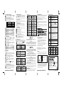
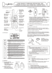
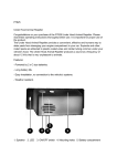
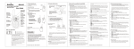
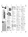
TREK100
Private mobile radio
USER GUIDE
Antenna
Indicator lighting
Enter/Key Lock/
Lamp Button
Ear/Mic jack
PTT (PUSH to TALK)
button - Press and
hold to transmit.
2.2 Installing the Belt Clip
a. Slide the Belt Clip into the
slot as shown in Figure 2.
b. A “click” indicates the Belt
Clip is locked into position.
Caution: Danger of explosion if battery is incorrectly placed. For
the regular batteries, replace only with AAA/LR03 or equivalent
type. For the Rechargeable battery pack, replace only with same
type and make of the battery pack that comes with the unit.
Belt clip
latch
Remove the batteries/battery pack if the unit will not be used for a long
period of time.
To reduce the risk of electric shock, do not expose this appliance to
rain and moisture.
3. Operation
Figure 1
Figure 2
a
DO NOT
CALL button
- Press to send
ringing tone to other
PMR units
Mosquito Repeller
Mic (Microphone)
Menu Button
-Press to program
the PMR settings.
Speaker
Car Adaptor charge
jack/AC-DC charge
jack
1. LCD Screen
Channel Number. Changes from 1 to 8
as selected by the user.
CTCSS Code. Changes from 1 to 38
as selected by the user.
Displays the current Battery charge
level.
Displayed when the Vox feature is enabled.
Displayed when transmitting a signal.
Displayed when receiving a signal.
Displays the transmitting Power level (Hi
/Lo
).
Blinks during Channel scan mode.
RSEL
TX Power H/L (High/
Low) button - Press to
select the power H/L
setting.
REVE
(Power) button
- Press and hold to
turn the PMR unit
ON or OFF.
(UP)/ (DOWN)
buttons - Press to
change channels,
volume, and to select
settings during
programming.
d
Figure 3
K
Y PAC
ED.
CAUS
BATTER
LD BE
ABLE
UIT WOU
HARGE700mAh E SHORT CIRC
4.8v Y, OTHERWIS
MBLE
ASSE
MON (Monitor)
button - Press to
monitor the current
channel.
2.1 Removing the Belt Clip
a. Pull the Belt Clip Latch away
from the PMR.
b. While pulling the Belt Clip
Latch, push up the Belt Clip
as shown in Figure 1.
H REC
Ni-M
LCD Screen
-Displays the current
channel selection and
other radio symbols.
Charging the Rechargeable Battery pack continue...
2. Installation
b
c
Charge
contact
pin
Charge
contact
point
Figure 4
Figure 5
a. Slide down the Battery Compartment Cover (Figure 3) latch located
on the bottom of the PMR, then slide down the Battery
Compartment Cover as shown in Figure 4.
b. Install the 4.8V, 550 mAh Ni-MH (Nickel Metal Hydride)
rechargeable battery pack (included) as shown in Figure 5. OR Use
4 x 1.5V AAA/LR03 regular alkaline batteries paying attention to the
polarity marking in the battery compartment.
c. Replace the Battery Compartment Cover.
d. Lock the Battery Compartment Cover Latch into position.
2.4 Charging the Rechargeable Battery pack
Note: Do not attempt to charge the PMR when using regular
alkaline batteries.
Using the AC-DC Adaptor (Dual type) plug
a. Insert the small plug on the end of the AC-DC adaptor into the
AC-DC charger jack located at the bottom side of the unit (Figure 6).
b. Plug the AC adaptor into the AC wall outlet.
Using the Car Adaptor charger plug (optional)
a. Insert the small plug on the end of the Car adaptor charger plug
into the Charger jack located at the bottom side of the unit (Fig. 7).
b. Plug the Car adaptor into the car cigarette socket.
When charging, the Battery level indicator icon will start scrolling on
the LCD Screen. It takes about 10 hours to fully recharge the battery
if they've become completely run down, new battery takes up to 14
hours to fully charge.
Displayed when the Dual Watch function is turned ON.
Displayed when the Key Lock feature is activated.
Displayed when sending Call-Ring tone to other PMR units.
Displays when the Stopwatch feature is turned ON.
Displays during Monitor operation, and Speaker volume selection.
Displays when the Mosquito Repeller function is activated.
Displayed when the Scrambler function is turned ON.
Important: Turn OFF the
PMR unit when charging.
Charge the Battery pack
10~14 hrs. prior to initial
use.
Figure 6
Figure 7
Notes:
Do not charge the battery using both AC adaptor and Car Charger
adaptor at the same time.
3.1 Turning the Unit ON/OFF
To Turn ON;
a. Press and hold the
(Power) button. A special “beep"
sound will be heard and the LCD Screen will display the
current channel.
To switch OFF;
b. Press and hold the
(Power) button. A special “beep"
sound will be heard and the LCD Screen will turn blank.
3.2 Adjusting the Speaker volume
There are 8 volume levels.
To adjust the speaker volume level, press the
(UP)
button to increase, or press the
(DOWN) button to
decrease. During the adjustment, the LCD Screen will
display the speaker icon and the corresponding number of
the volume level at the lower left corner.
3.3 Receiving a Call
The unit is continuously in the Receive mode when the
unit is turned ON and not transmitting. When a signal is
received on the current channel, the RX icon
will be
displayed on the LCD Screen and the LED indicator will
turn on.
3.4 Transmitting (sending)
a. Press and hold the PTT (Push to Talk) button to transmit
your voice. The TX icon
will display on the LCD Screen.
b. Hold the unit in a vertical position with the Mic
(Microphone) 5 cm away from the mouth. While holding
the PTT button, speak into the mic (microphone) in a
normal tone of voice.
c. Release the PTT button when you have finished
transmitting.
Important:
Check the channel activity by pressing and holding the M (Monitor)
button. You will hear static if the channel is unoccupied. Do not
transmit if someone is talking on the current channel.
In order for other people to receive your transmission, they must
also be on the same Channel and CTCSS code (if applicable) that
you are currently using. Refer to the "Changing Channel" section
for more information.
4. Functions and Settings
4.1 Changing Channels
The PMR has 8 available channels. To change channels, in
normal mode;
a. Press the
button once, the Channel number icon will
start blinking on the LCD Screen.
Changing Channels continue...
b. While the Channel number icon is blinking, press the
(UP) or
(DOWN) button to select the desired channel.
The channel changes from 1 to 8, or from 8 to 1.
c. Press the
(Enter) button to confirm your selection and
return to the normal mode.
Note:
Refer to the "Channel Table" section of this Owner’s Manual for
detailed frequency listing.
4.1.1 Monitor
You can use the Monitor feature to check for weak signals
on the current channel.
a. Press the
button for 1 second to hear everything on
the current channel for 15 seconds.
Press the
button again to turn off the Monitor
operation.
4.2 Changing the CTCSS sub-channel
Each of the 1-8 channels has 38 sub channels (CTCSS code),
letting you to set up group of users within the same channel.
To change the CTCSS sub-channel;
a. Press the
button twice, the CTCSS number icon will
start blinking on the LCD Screen.
b. While the CTCSS number icon is blinking, press the
(UP) or
(DOWN) button to select one of the 38 CTCSS
sub-channels. (Set this option to “00” to allow the user to
transmit and receive a call using the main channels only.)
c. Press the
(Enter) button to confirm your selection and
return to the normal mode.
4.3 Setting the Channel Scan
Channel scan performs searches for active signals in an
endless loop from channels 1 to 8. To turn ON;
a. Press the
button 3 times, the
(SCAN), Channel
number, and the CTCSS number icons will start flashing on
the LCD Screen.
(UP) or
(DOWN) button to activate the
b. Press the
channel scan mode.
c. The channel number on the LCD Screen changes rapidly
until an active signal is detected. (To deactivate the
channel scan mode, press the
(Enter) button. The LCD
Screen will immediately return to the normal mode with
the previous channel setting.)
d. When an active signal (one of the 8 channels) is detected,
channel scan pauses on the active channel.
(Enter) button to communicate with the active
e. Press the
signal channel, and the channel scan will be deactivated.
Note:
When the Channel Scan is activated, the VOX function will be
temporarily disabled until the Channel Scan function is turned OFF.
4.4 Setting the Scrambler Mode
The Scrambler mode makes your transmission voice sounds
garbled to anyone listening. To operate this function, both
PMR units (Transmitting and Receiving units) must be set with
the same Scrambler mode setting. To activate the Scrambler
mode;
a. In normal mode, press the
button 4 times, the
(Scrambler icon) will display and the OFF icon will start
blinking on the LCD Screen.
(UP) button or
(DOWN) button to select
b. Press the
the desired scrambler mode (off, 1, 2, 3, or 4).
Setting the Scrambler Mode continue...
c. Press the
(Enter) button to confirm your selection and
return to the normal mode.
4.5 Changing the Call-Ring tone
You can use the Call-Ring tones to alert the other user/s or to
identify yourself. The PMR is equipped with 10 different types
of Call-Ring tones. To change the Call-Ring tone setting, in
normal mode;
a. Press the
button 5 times, the
(Call-Ring tone
icon) will be displayed on the LCD Screen and the current
Call-Ring tone number will start blinking.
b. While the Call-Ring tone icon is blinking, press the
(UP)
or
(DOWN) button to change the setting. A respective
Call-Ring tone sound will be played when changing from
one tone to another.
c. Press the
(Enter) button to confirm your selection and
return to the normal mode.
4.5.1 Sending a Call-Ring tone
a. With the PMR in normal mode, press the
button.
The microphone will be muted and the unit will
transmit the current Call-Ring tone to other user/s
set to the same Channel and CTCSS code.
4.6 Setting the DW (Dual Watch)
This unit is capable of monitoring two channels (main channel,
and the DW channel) in the standby mode. However, the unit
can only transmit a call using the main channel. The DW
channel can only monitor/receive a call transmitted by other
users with the same channel and CTCSS code setting as the
DW channel. To activate the Dual watch mode;
a. In normal mode, press the
button 6 times, the
(DW) icon will start blinking on the LCD Screen.
b. Press the
(UP) or
(DOWN) button to select the
DW (dual watch) channel (1~8, except the main channel).
Otherwise, set this option to “OFF.”
c. Press the
(Enter) button to confirm your selection and return
to the normal mode.
In the normal mode, the LCD screen will alternately display
the Main and the DW channel numbers. Whereby the CTCSS
code is applicable, the user must set first the CTCSS code
number prior to setting the DW channel number.
Note:
When the Dual Watch function is activated, the VOX function will
be temporarily disabled until the Dual Watch mode is turned OFF.
4.7 Setting the VOX (Voice Activated) Sensitivity
In VOX mode, the PMR will transmit a signal only when it is
activated by your voice or other sounds around you. The unit
will transmit for a further for 1 second even if you stop talking.
To set the VOX sensitivity level;
a. Press the
button 7 times, the
(Vox) icon will
start blinking on the LCD Screen.
b. Press the
(UP) or
(DOWN) button to select the
VOX (off, 1, 2, 3, or 4) sensitivity.
c. Press the
(Enter) button to confirm your selection and
return to the normal mode.
While the VOX mode is on, pressing the
(enter) button for
1 second can suspend the VOX transmission for 4 seconds.
VOX operation is not recommended if the PMR will be used
in a noisy or windy environment.
4.8 Setting the Mosquito Repeller Mode
a. In normal mode, press the
button 8 times, the
(Mosquito Repeller icon) will display and the “OFF” icon will
start blinking on the LCD Screen.
b. Press the
(UP) or
(DOWN) button to select your
preferred mosquito repeller frequency (1~4) or set
this option to “Off.” The table below shows the Mosquito
Repeller frequency chart setting.
Item
Frequency
Cadence
1
48Hz
Continued
2
3
6.5KHz
5.5KHz, 6.5KHz, 7.5KHz, 8.5KHz, 9.5KHz
Continued
6s for each frequency
4
6.5KHz - 9KHz
Sweeping
Note:
To get the best performance, try to adjust to different frequency.
The Mosquito Repeller signal can not be activated during
Transmitting, Receiving, Monitoring, Channel Scan and Dual
Watch scan operation.
It is not recommended to use the Mosquito Repeller with high VOX
sensitivity. The PMR may be triggered to transmit signal
accidentally using the Mosquito Repeller signal.
4.9 Setting the Stop-Watch
a. In normal mode, press the
button 9 times, the
(Stop-watch icon) will display and the Channel icon will
be blinking on the LCD Screen.
b. Press the
(UP) button the timer start counting on the
LCD Screen.
c. Press the (DOWN) button to stop the timer from counting.
Pressing the
(DOWN) button again to reset the timer
display back to zero.
button to return to the normal mode.
d. Press the
Note:
The PMR’s Transmit and Receive function will still operate even if
the Stop-watch function is in operation. However, the Call-Ring
tone function will be temporarily disabled.
5.3 Busy Indicator (RSSI Indicator)
Anytime when the PMR detects a valid signal on the current
channel, the BUSY indicator will display on the LCD Screen and
the Indicator lighting will light green. However, the speaker will
only be enabled when the signal matches the current CTCSS code.
5.4 LCD Screen Back Light
Every time a button is pressed (except PTT, Call, and Power
buttons), the LCD Screen back light will illuminate for 4 seconds.
5.5 Microphone/Earphone Jack
The PMR is equipped with an auxiliary microphone and
earphone jack (located at the upper side near the antenna).
The headset may or may not be included with the package.
5.6 Battery Meter Indicator
The PMR can detect the battery charge in the following levels;
Battery charge at high level.
Battery charge at medium level.
Battery charge at low level.
At this level, the PMR will emit a “beep” sound for every
15 seconds in normal mode.
Important: Charge the unit for 10~14 hours.
Battery charge at very low level. At this level, the other
icons in the LCD Screen also turns OFF.
Important: Charge the unit for 10~14 hours.
5.7 Restore Default Settings
This feature allows the user to restore the setting of channel, CTCSS,
&
Volume, VOX, Scrambler mode, Mosquito Repeller, and Tx power level.
a. In normal mode, press and hold the
and
(Power) buttons
first, and then quickly press the PTT button. The PMR will
restore all default settings as the following table.
Channel
CTCSS sub code
01
00
Scrambler mode
Mosquito Repeller
OFF
OFF
Volume
VOX
08
OFF
Hi/Lo Power
High
Call Melody
No. 7
6. Specifications
5. Auxiliary Features
5.1 Key Lock
The Key Lock feature allows the user to disable the
(UP),
(DOWN), Monitor, and the Menu buttons so that the PMR
settings could not be changed accidentally.
a. To activate the Key Lock feature, press and hold the
button until the
(Lock) icon appears on the
LCD Screen.
b. To deactivate the Key Lock feature, press and hold the
button until the
(Lock) icon disappears on the
LCD Screen.
The PTT, H/L, Call, and the
(Power) buttons will remain
functional even if the Key Lock feature is activated.
5.2 TX Power H(High)/L(Low) feature
This feature permits the selection of the transmitting power
level to high or low. Before transmitting a speech to other PMR
units, press the H/L button to select the desired power output .
If High is selected, the PMR will transmit at maximum power
and at a longer transmission range.
Binatone Help Line - 0845 345 9677
Channels Available
8 Channels
CTCSS Sub-channel
Output Power (TX)
38 for each Channel
0.5W
Range
About 8 Kms. (High) / 4 Kms. (Low)
Channel Frequency Table
Channel
Frequency (MHz)
Channel
Frequency (MHz)
1
446.00625
5
446.05625
2
446.01875
6
446.06875
3
446.03125
7
446.08125
4
446.04375
8
446.09375
CTCSS (Continuous Tone Coded Squelch System)
Code
Frequency (Hz)
Code
Frequency (Hz)
1
67.0
20
131.8
2
3
71.9
74.4
21
136.5
22
141.3
9. Guarantee and service
CTCSS Continue...
Code
Frequency (Hz)
Code
Frequency (Hz)
4
5
6
77.0
79.7
82.5
23
24
25
146.2
151.4
156.7
7
85.4
26
162.2
8
88.5
27
167.9
9
91.5
28
173.8
10
11
94.8
97.4
29
30
179.9
186.2
12
100.0
31
192.8
13
103.5
32
203.5
210.7
14
107.2
33
15
110.9
34
218.1
16
114.8
35
225.7
17
118.8
36
233.6
18
123.0
37
241.8
19
127.3
38
250.3
10. Troubleshooting Guide
The Binatone TREK 100 is fully guaranteed for 12 months from the date
of purchase shown on your sales receipt. The guarantee does not cover
damage by misuse or negligence, or by excessive voltage.
Please keep your sales (till) receipt - this is your guarantee. You should
also keep the original packaging materials.
When unpacking your Binatone TREK 100, check for visible damage. If you
see any damage, do not use the PMR - return the whole unit to where
you bought it.
If your Binatone TREK 100 develops a fault, refer to the “Troubleshooting
Guide.” section of this manual. If you can’t solve the problem, return the
whole unit as follows;
Solution
Symptom
No power.
Check the battery pack is installed properly.
The batteries may be weak.
Replace the old battery pack with a new one.
Reception
is weak.
Press the (UP) button to increase the receiver volume level.
The receiving signal may be weak and/or out of range.
If this happens press the M (Monitor) button.
Cannot change
CTCSS subchannels.
Key lock mode must be deactivated if the Key lock icon ( ) is
displayed on the LCD Screen.
To change CTCSS sub-channel, press the
(Menu) button twice,
the CTCSS icon blinks on the LCD Screen. Press the (UP) or
(DOWN) button to change the CTCSS sub-channel.
Batteries may be weak.
Range is limited.
Replace with new batteries if the charge level indicator gets low.
Check the TX Power H/L setting. See the “Effective Range” diagram.
The maximum range will vary depending on terrain and environment.
Open fields provide the maximum range, while steel/concrete
structures, heavy foliage, and use in buildings and in vehicles may
limit the range significantly.
Wearing the radio close to the body, such as in a pocket or on a
belt, will decrease range; change the location of the radio.
Sound distortion
problems.
If you are transmitting, speak in a normal tone of voice, 5 cm
away from the Mic (microphone.).
If you are receiving, lower the volume to a comfortable level.
Radios too close. Radios must be at least 2 meters apart; increase
your distance.
Radios too far apart. Obstacles interfere with transmission. Talk
range is up to 8 Km (High power), 4 Km (Low power) in clear
unobstructed conditions.
Scrambler mode
not operable.
Check the Scrambler mode setting. Both PMR units (Transmitting and
Receiving) should be set to the same Scrambler mode setting.
No communication.
Check the Channel and the CTCSS code setting. Both PMR units
(Transmitting and Receiving) should be set to the same Channel and
CTCSS code (if applicable) setting.
Mosquito Repel
not effective.
Adjust the Mosquito Repeller frequency and check the most effective
frequency to get the best performance.
7. Safety
CAUTION
Damaged Antenna
Do not use any PMR that has a damaged antenna. If a damaged antenna comes
in contact with the skin, a minor burn may result.
Batteries
All batteries can cause property damage and/or bodily injury such as burns if
conductive material such as jewelry, keys, or beaded chains touch exposed
terminals. The material may complete an electrical circuit (short circuit) and
become quite hot. Exercise care in handling any charged battery, particularly
when placing it inside a pocket, purse, or other container with metal objects.
WARNING
For Vehicles with an Air Bag
Do not place your PMR in the area over an air bag or in the air bag deployment area.
Air bags inflate with great force. If a PMR is placed in the air bag deployment
area and the air bag inflates, the PMR may be propelled with great force and
cause serious injury to the occupants of the vehicle.
Potentially Explosive Atmospheres
Turn your PMR OFF when in any area with a potentially explosive atmosphere, unless
it is a type especially qualified for such use (for example, Factory Mutual Approved).
Sparks in such areas could cause an explosion or fire resulting in injury or even death.
Repair after the Guarantee has expired
If the unit is no longer covered by Guarantee, first follow steps 1 as for
repair under Guarantee, Then...
2. Call our service Department on 0845 345 9677 and ask for a
quotation of the repair charge, and details of where to send your
TREK 100 for repair.
3. Return your TREK 100 to the address given by the Service
Department, making sure to include your name and address, and a
cheque or postal order for the value of the repair charge.
Binatone Telecom plc operates a policy of continuous product
improvement, and so reserves the right to make changes to the product
and functions without prior notice.
Effective Range
The Transmission range of the product is dependent on the environment
terrain where it is being used, the following diagram attempts to guide
the user on the sort of performance to expect for everyday use.
Signal Strenght
Optimum (open area) (1)
Batteries
Do not replace or charge batteries in a potentially explosive atmosphere. Contact
sparking may occur while installing or removing batteries and cause an explosion.
Blasting Caps and Areas
To avoid possible interference with blasting operations, turn your PMR OFF near
electrical blasting caps or in a “blasting area” or in areas posted: “Turn off the twoway radio.” Obey all signs and instructions.
NOTE: Areas with potentially explosive atmospheres are often, but not always,
clearly marked. They include fueling areas such as below deck on boats; fuel or
chemical transfer or storage facilities; areas where the air contains chemicals or
particles, such as grain, dust, or metal powders; and any other area where you
would normally be advised to turn off your vehicle engine.
This equipment is intended for use in:
This does not affect your statutory rights.
Medium ground based
obstruction (2)
Spain
Austria
Finland
Latvia
Belgium
France
Liechtenstein
Sweden
Bulgaria
Germany
Luxemburg
Switzerland
Croatia
Greece
The Netherlands
Turkey
Cyprus
Hungary
Norway
UK
Czech
Iceland
Poland
Romania
Denmark
Ireland
Portugal
Slovakia
Estonia
Italy
Slovenia
Countries of use
Declaration of Conformity
The Binatone TREK 100 complies with the essential requirements
Heavily built up area (3)
0
Range (Km)
8
Range Slope
Range Check
The Transmission range will be affected as shown in the above diagram.
The transmitting range typical values for different environment conditions
will be (1) 8 km (2) 4 km (3) 2 km. It should be remembered that
these are only guide values as actual achieved distances will be
dependent on the environment and terrain.
And conforms to the following relevant standards:
Waste electrical products must not be
ETSI EN 300 296-2 V1.1.1
disposed of with household waste.
ETSI EN 301 489-5 V1.3.1
This equipment should be taken to
your local recycling centre for safe
ETSI EN 301 489-1 V1.4.1
treatment.
EN 60065: 2002
Binatone Telecom plc operates a policy of continuous product
improvement, and so reserves the right to make changes to the product
and functions without prior notice.
8. Cleaning and Care
To clean your PMR, use a soft cloth dampened with water. Do not use cleaners or
solvent, which may cause damage that may not be covered by guarantee.
Binatone Help Line - 0845 345 9677
UK (BTP) Ver 4 Jan 06