1
MOSAIC TRAINING
INSTALLATION INSTRUCTIONS…………………………………………….. 2
DATABASE DESIGNER………………………………………………………... 6
WORKSTATION CONFIGURATION………………………………………… 29
CARD DESIGNER……………………………………………………………... 54
CAPTURE PROGRAM………………………………………………………. 110
IMAGE FILE & DIRECTORY NAMES EXPLAINED…………………….... 132
NETWORKING……………………………………………………………….. 135
THE TUTILITY PROGRAM…………………………………………………. 138
DATABASE DOCTOR……………………………………………………….. 139
1
INSTALLATION INSTRUCTIONS
Thank you for choosing NBS Mosaic for Windows.
It is essential that you follow these instructions to ensure that your card personalisation
system is set-up and running as rapidly as possible, and with least difficulty.
NBS Mosaic for Windows will work with the following operating systems:
Microsoft Windows 95
Microsoft Windows 98
Microsoft Windows NT Version 4.0
Microsoft Windows 2000
Microsoft Windows XP.
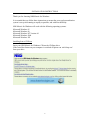
Installing from a CD-Rom
Insert your NBS Mosaic for Windows CD into the CD-Rom drive.
If the Auto-Run feature on your computer is switched off please run ‘mfwSetup.exe’
from your drive.
2
INSTALLATION INSTRUCTIONS
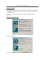
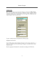
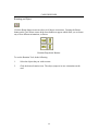
Dongle Driver Setup
The Sentinel Dongle Driver setup wizard will install your dongle software allowing you
to run NBS Mosaic for Windows. You will be required to re-boot your system after this
installation is complete.
Exit from this wizard and run ‘MFWSetup.exe’ again to install NBS Mosaic for
Windows.
NBS Mosaic for Windows Setup
Click Next to continue.
Click next to Continue.
3
INSTALLATION INSTRUCTIONS
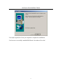
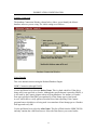
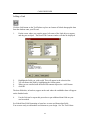
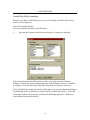
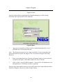
Files for NBS Mosaic for Windows application will be copied to your computer. This
will include programs for the Borland Database Engine.
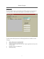
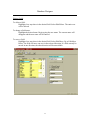
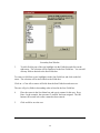
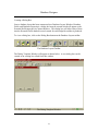
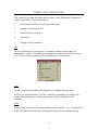
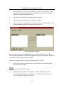
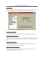
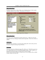
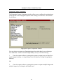
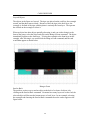
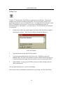
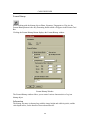
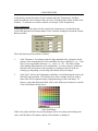
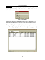
After this process has completed you will be presented with the following screen:
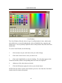
Please select the frame grabber installed on your computer and ‘Next’ to continue.
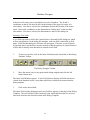
Now select the type of photo capture device you wish to run with NBS Mosaic for
Windows. If you are using a Twain device, please ensure that the appropriate software is
installed on your computer for that device.
You can amend these selections in ‘Workstation Configuration’ later.
4
INSTALLATION INSTRUCTIONS
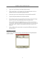
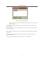
You maybe required to re-boot you computer to complete the installation.
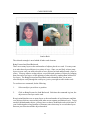
You have now successfully installed NBS Mosaic for windows. Have fun !
5
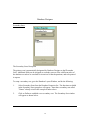
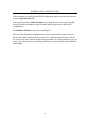
Database Designer
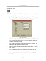
The purpose of Database Designer is to create and format the database into which all of
the ‘Personal Profiles’, or demographic information, about your ID Cardholders will be
stored.
Later, this demographic information will be combined with captured images to produce
the finished cards.
Understanding Tables
A database is an organised collection of information or data. A telephone book could be
considered a simple form of a database. It organises data about people under specific
headings: names, phone numbers and addresses.
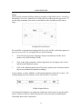
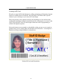
A database created using ‘Database Designer’ is organised as a table. Each row of a table
contains one individual record. Each column in the table contains one element of the
information that makes up a record; this is called a field.
The example below shows the contents of a table that could be created with Database
Designer.
ID
00000001
00000002
00000003
00000004
00000005
Last Name
Smith
Squires
Naldrett
Davies
Lane
First Name
Jane
Gavin
Stephen
Stephen
Darren
Initial
B
J
J
M
H
6
Birth Date
03/07/1959
12/08/1961
31/08/1961
12/12/1978
08/08/1973
Car Reg.
R590 NDV
N624 SPF
T439 TWR
G623 YWQ
T298 DFV
Database Designer
Understanding Sorts
A sort is a list of data items in ascending or descending order. Sorts allow you to control
how the records in a table are displayed, reported and printed. Sorts maybe be based on
any element of data in a record, such as ID number, or last name or GPO code. Sorts are
established in Database Designer, and then are used in the ‘Capture’ application to place
records in a desired order. Database Designer allows the use of the following two types of
sort.
Primary Sort
The primary sort is the default order of the records in a database. Database Designer
automatically assigns the primary sort default to the ID Number field, in ascending order.
The primary sort is identified by a “P” (for primary) in the Database Layout Window sort
column.
The primary sort requires that the number in the ID number field is different for every
record, or Personal Profile, in your database.
Secondary Sorts
A secondary sort can provide another way to sort the records in a database when
searching in ‘Capture’.
Creating a Database
It is recommended that you make planning the database the first step in preparing a
database layout. You should decide up front what you want in the database and how you
want to lay it out. While you are planning, keep these ideas in mind.
•
Think small. Put as little information as possible in each field. For example, break
the name field down into Last name, First name and Middle initial. This will
allow for easier maintenance and sort methods in the future.
•
Be complete. Include fields for all the data you will need, but don’t add data you
may not need. Additional fields can be added later, if necessary.
•
Be consistant. Create a database layout that uses the same names and
organisations as the forms and files you already use.
7
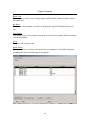
Database Designer
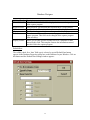
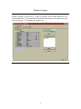
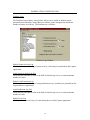
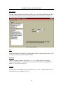
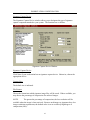
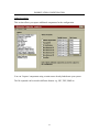
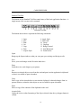
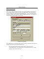
Defining Fields
To create a database layout, you must define each field by naming it and specifying the
field’s type and size. This is done in the Database Layout Window, shown below.
To make creation of the layout easier, the following functions are available for certain
field types.
•
•
•
•
•
define validity check for individual fields.
define lookup tables for individual fields
establish an applicant name link used in the ‘Capture’ application for clarity when
viewing records.
Designate a field as a secondary sort.
Special processing.
8
Database Designer
Fields are defined in a list in the Database Fields box. You can use the mouse, arrow
keys, Enter key, or Tab key to move around between rows and columns. A vertical scroll
bar will appear in the Database Fields box when there are more fields than can be
displayed at one time.
Field Names
Type the name of the field in the Field Name column of the Database Fields list. Field
names must meet the following guidelines.
•
•
•
maximum length is 31 characters
no two names in one layout can be exactly the same.
Names should contain only letters and numbers, no additional symbols should be
used. Do not include any spaces.
Field Types and Sizes
1.
2.
3.
4.
Highlight the Type box for the desired field.
Press the spacebar or click on the down arrow on the right side of the type box. A
drop down menu of types will appear.
Highlight the desired type and press enter. The highlight will move to the Size
box.
Type in the desired size staying within the limits stated in the table below. If a
size is not entered, Database Designer assumes the default value for the associated
type.
Field Type
Text
Size Range
1 - 255
Character
1
Integer
Long Integer
Floating Point
-32,766 to +32,766
-2,147,483,646 to
+2,147,483,646
Virtually unlimited
Date
N/A
Time
N/A
Description
Allows the input of letters, numbers and any
special characters on the system keyboard.
Allows the input of letters, numbers and any
special characters on the system keyboard.
Allows the input of whole numbers.
Allows the input of whole numbers.
Allows the input of numbers containing a decimal
point.
Allows the input of any valid date. Leap years are
handled automatically.
Allows input of time of day, stored in
milliseconds since midnight.
9
Database Designer
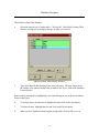
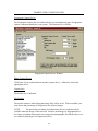
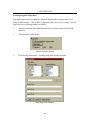
Opening an Existing Database Layout File
To open an existing database layout file, do the following:
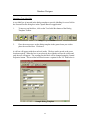
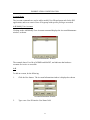
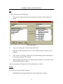
1.
Click on the "open existing file" icon or select File|Open. The Open window will
appear as shown. All database layout (.dbl) files in the default directory will be
displayed in the File Name selection box.
2.
The Open window also contains a File Type list (all files created with Database
Designer will be ".dbl" files) and a Drives list. To select an existing .dbl file from
another drive, click on the down arrow. A list of available drives will appear.
Click on the desired drive (or TAB over to the field, use the up-down cursor keys
to select it and press ENTER). A new file list will appear under the File Name
selection box.
3.
Select the file to open.
Editing Fields
To delete a field:
Highlight a box anywhere in the desired field. Select Edit/Delete. The entire row
will be deleted.
To change a field name:
Highlight the desired name. Begin typing the new name. The current name will
disappear and the new name will be entered.
To move a field:
Highlight a box anywhere in the desired field. Select Edit/Move Up or Edit/Move
Down. The field will move one row in the selected direction. If a field can only be
moved in one direction, the other direction will be unavailable.
10
Database Designer
Editing Fields
To delete a field:
Highlight a box anywhere in the desired field. Select Edit/Delete. The entire row
will be deleted.
To change a field name:
Highlight the desired name. Begin typing the new name. The current name will
disappear and the new name will be entered.
To move a field:
Highlight a box anywhere in the desired field. Select Edit/Move Up or Edit/Move
Down. The field will move one row in the selected direction. If a field can only be
moved in one direction, the other direction will be unavailable.
11
Database Designer
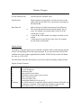
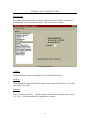
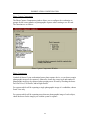
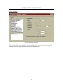
Validity Checks
Rules which limit what you can enter into a field type are known as Validity Checks.
These rules ensure that the data entered into a field in the ‘Capture’ program is valid. If
an attempt is made to enter a value that falls out of the range of the validity check, the
capture program will not accept the entry.
To place a validity check in a field perform the following steps.
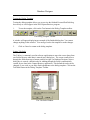
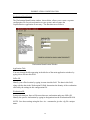
Highlight the desired field.
Select Validity Checks from the Database Properties list. The checks, numbered 1 – 6,
which are available for the selected field type will appear. Unavailable checks will be
displayed in gray.
Enter the appropriate information for each number according to the Table below.
12
Database Designer
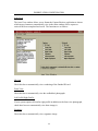
Validity Check
Show in Search
Required Field
Minimum
Maximum
Default
Display Format
Description
When checked this field will be displayed when a search is performed
in the capture program.
When checked, specifies that this field must have a value entered.
Specifies the smallest value that can be entered in this field.
Specifies the largest value that can be entered in this field.
The value entered here will automatically appear in the field in the
capture program. This field can be changed in the capture program
when necessary.
Allows you to enter specific text that serves as a template for data
entered in this field. This template formats the information entered
into this field in the capture program.
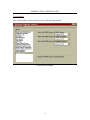
Default Date
The validity check for a ‘date’ field type is selected, a special Default Date button
appears in the Database Properties group box on the Database Layout Window. Click on
this button and the Default Date Settings window appears :
13
Database Designer
Do Not Initialise Date
Does not provide a default Value
Specific Date
allows selection of certain date. Use the arrow keys to the
right of the Specific Date box to increment or decrement to
the desired date.
Base Date On
allows selection of a date based on one of the following:
The current date plus/minus the desired months, days or
years, for example, an expiration date can be set as the
current date +4 years.
A specific day of the month, for example, the third of each
month.
A date based on a specific day of the week, for example,
the last Friday in the month.
Display Format
The display format box allows you to establish a template which format the data entered
into the corresponding field in the capture program. If you enter the format 99999-9999
and then enter in the Capture application the number 123456789, the system will format
the value as 12345-6789.
The table below describes the characters you can use when developing a display format.
Display Format Characters
Character
X
9
A
N
U
L
H
Constants
What It Represents
any ASCII character
any numeric digit
upper and lower case letters
any number or letter (upper case or lower)
Upper case letters only
Lower case letters only
hexadecimal numbers (0,9,a,b,c,d,e,f)
Any ASCII character except those listed in the left column of this table can
be entered as a constant. These characters will always appear in the
entered data exactly as you specified in the display format.
14
Database Designer
Lookup Tables
A lookup table is a data entry tool. The Lookup Table function is part of the Database
Properties group box of the Database Layout Window. It provides an alternative
acceptable entry for the associated field. Its purpose is often to substitute a more pleasing
version of a value for the coded entry in a field, for example, "female", instead of "F".
Lookup tables can be constructed in either of the following two types.
Indirect -
When designing this type of table, you must enter a value and a
description. When the dialog box is displayed in the Capture/Retrieve
application, the field will have a drop-down list containing the description
only.
Direct -
When designing this type of table, you enter a value only. This value is
displayed in the Capture/Retrieve application in the field's drop-down list.
To add a lookup table, perform the following steps.
1.
Highlight the desired field in the Database Layout window.
2.
Select Lookup Table from the Database Properties list. Existing tables can be
modified or erased.
3.
Click on define and the Define Lookup Table window will appear.
.
15
Database Designer
The Define Lookup Table Window
4.
Select the desired type of lookup table. Click on OK. The Modify Lookup Table
Window will appear, according to the type of table you selected.
Indirect Lookup Table Modify Window
5.
Type in the desired data, pressing Enter after each entry. The next figure shows
an example of an indirect lookup table created for the "Eyes" field in the Database
Layout window.
Entries can be rearranged by highlighting a row and clicking on one of the arrow buttons
shown in the figure.
6.
To arrange entries in numerical or alphabetical order click on the Sort button.
7.
To delete an entry, highlight the row and click on the Delete button.
8.
When you have finished constructing the lookup table, click on OK to save it.
16
Database Designer
Applicant identity links
Applicant Identity Links Group Box
The Applicant Identity Link function, found in the Database Properties group box of the
Database Layout Window, provides a way to clearly identify an applicant's name from
among the data fields which you create. Specifying a name link in the database layout
allows the link to be displayed on the Capture/Retrieve Profile ID Display whenever a
personal profile is open. The link will also display the name when printing an ID. Refer
to the Capture/Retrieve application.
Three name fields are provided for linking: last name, first name, and middle initial.
You can select any field that has been previously defined to link to Capture/Retrieve.
To link fields, select Applicant Identity Links from the Database Properties list. The
functions available in the Applicant Identity Links group box will appear as shown
above.
17
Database Designer
1.
Select Database Contains Link.
2.
Type in the desired field name or select a name from the drop-down list by
clicking once on the down arrow on the right side of the box. You do not have to
select the last name field to be displayed in this box but an entry must be made
here to use the Applicant Identity Link function.
3.
If you would like to display more than one field, click on the small box in front of
"Link Field 2". This activates the Link Field 2 box and allows you to make an
entry in this box.
4.
To add a third field, click on the small box in front of “Link Field 3”. The third
field that appears in Capture/Retrieve will only display entries which contain one
character.
5.
Save the database, and the applicant identity link is saved along with it.
18
Database Designer
Secondary Sorts
The Secondary Sorts Group Box
The primary sort is automatically designated by Database Designer as the ID number
field. Additional fields can be assigned as secondary sorts to allow a different order of
the database records to be searched for in retrieval or batch operations, and to be printed
in reports.
To setup a secondary sort, go to the Database Layout Window, and do the following:
1.
Select Secondary Sorts from the Database Properties list. The functions available
in the Secondary Sorts group box will appear. Note that a secondary sort called
"Names" already exists in the example window above.
2.
Click on Define to establish a new secondary sort. The Secondary Sort window
will appear as shown below.
19
Secondary Sort Window
3.
To add a field as part of the sort, highlight it in the Fields box and click on the
right arrow. The selection will be transferred to the Sort Fields box. You can add
as many fields as desired to the Sort Fields box.
To remove a field from a sort, highlight it in the Sort Fields box and click on the left
arrow. The selection will be moved back to the Fields box.
Click on <<Clear All to remove all fields from the Sort Fields box and start over.
The sort will go by fields in descending order as listed in the Sort Fields box.
4.
Place the cursor in the Sort Name box and type in a name for this sort. Press
Enter. In the example, the sort name "Location" has been assigned. The OK
button will become active after a name has been entered.
5.
Click on OK to save the sort.
20
Database Designer
Database Designer will place an "S" in the Sort column for each field included in a sort,
as illustrated below. If a certain field is included in more than one secondary sort, only
one S will appear. "P" designates the primary sort.
21
Database Designer
Special Processing
To attach Special Processing to a field, perform the following steps.
1.
Highlight the desired field.
2.
Select Special Processing from the Database Properties List. The checks which
are available for the selected field type will appear.
3.
Increment after Print. This will add one to the accumulated field after the
successful printing of a card.
4.
Pad with spaces. This will pad the field with spaces up to the defined length.
5.
History Database. These checks are used to connect the main database to a
History Database. You can select which fields are to be stored and viewed in the
Capture Application.
6.
Card Link. This can only be highlighted against a text field of 8 characters. The
field is cross-referenced against the name of a card design when the record is
entered in the Capture application.
22
Database Designer
Creating a Dialog Box
Once a database layout has been constructed (see Database Layout Window, Database
Fields, and Database Properties), a dialog box must be created which will appear as the
Personal Profile input box in Capture/Retrieve. This dialog box will allow entry of data
into the Personal Profile database record created for each badge/id card that is produced.
To view a dialog box, click on the Dialog Box button on the Database Layout toolbar.
The Database Layout Toolbar
The Dialog Template Window will appear as shown below. A new dialog box can be
created or an existing box edited from this window.
The Dialog Template Window
23
Database Designer
In the lower left corner, the screen displays two sets of numbers. The X and Y
coordinates on the far left describe the current location of the upper left corner of a
selected box. If no box is selected, the coordinates describe the location of the mouse
arrow. Next to the coordinates are the dimensions in "dialog units" of the currently
selected box. If no box is selected, the dimensions are those of the dialog box.
Inserting a Text Field
A text field represents a field in the Capture/Retrieve Personal Profile dialog box which
will accept input data. In the dialog box template, each text field is titled with its field
name. In the finished dialog box, this title will not appear. Therefore, a text field must
be inserted, then a text label box must be inserted so that the operator of Capture/Retrieve
will be able to identify what data must be entered in each field.
1.
To insert a text field, click on the Insert Field button (the chain link) of the Dialog
Template Toolbar.
The Dialog Template Toolbar
2.
Move the mouse arrow to any point on the dialog template and click the left
mouse button once.
The Insert Field Window appears. A list of field choices displays all fields which were
created in the database layout, except those which have already been inserted into the
dialog template.
3.
Click on the desired field.
The Insert Field window disappears and a text field box appears on the edge of the Dialog
Template. The text field box will be bordered in red, which indicates that it is selected
and can be moved to the desired location in the Dialog Template.
24
Database Designer
Inserting a Text Label Box
A text label box is inserted in the dialog template to provide labelling for a text field in
the Personal Profile dialog box in the Capture/Retrieve appplication.
1.
To insert a text label box, click on the Text Label Box button of the Dialog
Template Toolbar.
The Dialog Template Toolbar
2.
Place the mouse arrow on the dialog template in the general area you wish to
place the text label box. Click once.
A red box will appear with the word text' inside. The box can be moved to the exact
location required. When the box is not selected, the red border will not be visible and
only the text will appear. The wording for this label will be changed using the Control
Properties button. This text label will then become a caption for the "id" field below it.
Sample Dialog Template
25
Database Designer
Testing the Dialog Template
Testing the dialog template allows you to preview the finished Personal Profile dialog
box exactly as it will appear in the IDS Capture/Retrieve program.
1.
To test the template, click on the Test button in the Dialog Template toolbar.
The Dialog Template Toolbar
A window will appear displaying an example of the finished dialog box. You cannot
change anything in this window. You must go back to the template to make changes.
2.
Click on Cancel to return to the dialog template.
Setting Tab Order
The Tab key is commonly used in software applications to move the cursor along from
one field to the next when data is entered into a dialog box. The cursor usually moves
through the fields from top to bottom, and left to right. In Database Designer, when a
dialog box is created, a default order for tabbing through the fields is automatically
created for use later in the Capture/Retrieve application. This default tab order can be
changed, if you wish, as you make final adjustments to the dialog template. Click on the
Tab Order button in the Dialog Template Toolbar.
The Tab Order Window
26
Database Designer
The default order for the fields is shown, with the first item in the list corresponding to
the first tab setting. Only "OK", "Cancel" and items with a field type of database' have
tab settings. All other static field types are not included in the tab order.
2.
Highlight an item and drag it to the desired position.
3.
When you have the items in the desired order, click on OK.
27
Database Designer
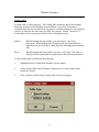
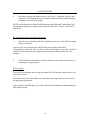
Saving Database Layout Files
To save a Database Layout file, do the following.
1.
Click on the "save file" icon in the Database Layout Toolbar or select File|Save.
If you are saving an existing file which has been updated, the file will be saved
automatically. If you are saving a new file, the Save As window will appear as shown.
The Save As Window
2.
Type in the desired filename.
The system will automatically attach a ".dbl" extension to the filename when it is saved.
To save the file to a directory other than that shown, first select another drive from the
Drives list.
28
WORKSTATION CONFIGURATION
This section file describes the details and procedures of the Workstation Configuration
software application. You will learn how to:
1.
identify and set defaults for individual workstations
2.
configure workstation devices
3.
monitor and log system data
4.
control ports
5.
configure software attributes
File
The File drop-down list, shown below, is a standard Windows menu heading for
manipulating .cfg files. The following commands are available on the File drop-down
list. Click on a listed command to see its definition, or see the list below.
File Menu
New
The New command is disabled in the Workstation Configuration application.
NOTE: New configuration files (.cfg) are created by first changing the settings, then
saving, then renaming new variations of the normal.cfg file using the Save As...
command.
Open
Allows you to load any saved configuration file with the identifier, .cfg. The default file,
which will load automatically upon starting up the application, is called normal.cfg.
29
WORKSTATION CONFIGURATION
Close
Closes the open .cfg file. The Main Menu Options list then becomes inactive until
another configuration file is opened.
Save
Saves the current configuration settings to the currently open .cfg file. The default file is
normal.cfg. It is recommended to save changed settings using the Save As command,
rather than changing the settings in the original normal.cfg file. You should save a copy
of normal.cfg in another directory so that you will always have an unchanged normal.cfg
file.
Save As...
Allows you to save configuration settings to a new .cfg file with a new filename of your
choosing, i.e., filename.cfg. As many different configuration settings as you wish may be
saved as .cfg files using Workstation Configuration. Each workstation in an office
system should have its own unique .cfg file.
Set Default Configuration
This is where you set the currently open .cfg file as the default to use when opening IDS
applications like Capture/Retrieve on the current workstation. Each individual
workstation should set its own unique .cfg file as the default.
Exit
Exit closes the Workstation Configuration application and returns you to the Windows
Program Manager.
30
WORKSTATION CONFIGURATION
Account Menu
The Account commands are used to add or modify User IDs and passwords for the IDS
applications, and to set certain Users off in groups with specific privileges as needed.
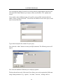
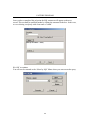
Add/Modify User Accounts
Clicking on the Add/Modify User Accounts command displays the Account Maintenance
window, as shown.
Account Maintenance Window
The example shows User Ids of ADMIN and MAINT, and indicates that both user
accounts are Active or accessible.
Add
To add an account, do the following.
1.
Click the New button. The Account Information window is displayed as shown.
Account Information Window
2.
Type a new User ID into the User Name field.
31
WORKSTATION CONFIGURATION
3.
If the account is to become active immediately, select Active from the Account
Status field. If the account is not to be immediately activated, select Disabled
from the Account Status drop-down list.
4.
Type in a Password for the account in the Password field.
5.
Type the same password into the Verify Password field.
6.
If a new account is to be added to a User Group, click on the Groups button. The
Group Membership window is displayed as shown below.
Group Membership Window
In the Available Groups list, highlight the group you wish to add the new account to.
Then click the Add button to add the user account to the group, and click OK. Repeat for
each group to which the account is to be added.
If the new account is not to be added to a group, skip step 7 for now.
7.
Click on OK in each Account window to accept the new account settings and
return to the main window.
Modify
To modify an account, do the following.
1.
Highlight an existing User Account name. Click the Modify button. The
Account Information window is displayed as previously shown. The selected
User Account will be shown in the fields.
32
WORKSTATION CONFIGURATION
2.
Type a new User ID into the User Name field if necessary.
3.
If the account Status is to be changed, select the appropriate status, Active or
Disabled, from the Account Status field drop-down list.
4.
If necessary, type in a new Password for the account in the Password field.
5.
Type the same password into the Verify Password field.
6.
If an existing account is to be removed from a User Group, click on the Groups
button to access the Group Membership window shown previously.
In the Available Groups list, highlight the group you wish to remove the new
account from. Then click the Remove button to delete the user account from the
group, and click OK. Repeat for each group from which the account is to be
removed.
7.
Click on OK in each Account window to accept the modifications and return to
the main window.
Add/Modify User Groups
Clicking on the Add/Modify User Groups command displays the Group Maintenance
window, as shown.
Group Maintenance Window
33
WORKSTATION CONFIGURATION
Add
To add a user group, do the following
1.
Click the New button, and the Group Information window will be displayed as
shown.
Group Information
2.
Type a new group name into the Group Name field.
3.
From the Group Status drop-down list, select whether the group will be Active or
Disabled.
4.
Click on the Users button to display the User Membership window and add users
to the group, and click OK to accept.
5.
When finished, click OK in the Group Information window to accept and return to
the Group Maintenance window.
The new group name will appear in the Group Maintenance window.
Modify
To modify a user group, do the following.
1.
Highlight the desired group name in the Group Maintenance window.
34
WORKSTATION CONFIGURATION
2.
Click on the Modify button. The Group Information window is displayed.
3.
Enter the desired modifications and click OK.
35
WORKSTATION CONFIGURATION
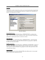
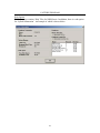
Workstation Identification
The Workstation Identification window, shown below, allows you to create a separate
configuration file for each workstation on your system, and to rename the
Capture/Retrieve application if necessary. The functions are as follows.
Workstation Identification Window
Application Title:
You may change the title appearing in the title bar of the main application windows by
typing a new title into this field.
Office ID:
Identify your office location by typing its name into this field. The data in this field,
along with the data in the Workstation ID field, determines the identity of the workstation
affected by the settings in this configuration file.
Workstation ID:
In network situations, there will be more than one workstation under one Office ID.
Identify the specific workstation by typing its designation into the Workstation ID field.
NOTE: Save these settings using the Save As... command to give the .cfg file a unique
name.
36
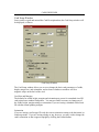
WORKSTATION CONFIGURATION
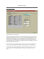
Database Connection
The database Connection Window, shown below, allows you to identify the Mosaic
database software you are using. The viable setting are as follows.
Database Connection Window
Native Paradox
This is the default selection using the Borland Database Engine.
ODBC Connection (through IDAPI).
Use the pull down list to select the Driver Name. This is a hard coded list. If the driver
being used is not specified, try Oracle. Although the specified name is passed to IDAPI, it
is also used by the Capture program when verifying databases. For instance, a Paradox
Date type specified in the DBL gets translated to a Date Stamp type in Oracle and
Access, which fails to verify against a Paradox Date when reopening. If the Capture
program knows which driver is being used it can translate a Date Stamp type to a Paradox
Date type and verify OK.
Use the pull down list to select the Alias Name. This list is filled form the ODBC.INI file
and only contains the valid Data Sources. Select the Data Source you created earlier.
37
WORKSTATION CONFIGURATION
If the username you specified in the IDAPI configuration requires a password, then enter
it in the Login Password field.
You can also specify the Table Username (eg for SQL Server) on this page. Note that
this is different to the database Login Username specified previously in the IDAPI
configuration.
The Database Extension is used for Crystal Reports.
The rest of the Workstation Configuration is as per a native Paradox system. However,
because the Paradox database directory will not be created, the image directory will not
be created. You must create the image directory manually. If you forget and try to save an
image, you will receive the error message which tries to resave the image with a different
colour depth.
38
WORKSTATION CONFIGURATION
Database Logs
The Database Logs window, shown below, allows you to enable or disable reports
generated from within the Capture/Retrieve software, and to designate the maximum
number of entries in each log. The functions are as follows.
Database Logs Window
Enable System Activity Log:
Check this box to record a log of system activity, which may be printed from the Capture
application.
Limit System Activity Log Size
Check this box and enter a value in the field to limit the log size to a certain maximum
number of events.
Enable Card Production Log:
Check this box to record a log of card production activity, which may be printed from the
Capture/Retrieve application.
Limit Production Log Size
Check this box and enter a value in the field to limit the log size to a certain maximum
number of cards.
Enable Event Log
Check this box to record a log of events during the use of the Capture application.
39
WORKSTATION CONFIGURATION
Data Files
The Data Files window, shown below, allows you to enter the path where the application
will look to access user accounts and other data that is common to all workstations on a
network. The functions are as follows.
Data Files Window
System Data Directory:
The default directory, created during Setup, is NBSIMAGE/DATA, as shown in the
figure. If the system data resides in another location, replace the default information by
typing the new path into the field or use the browse feature.
Image Directory:
The default directory, created during Setup, is NBSIMAGE/DATA. If the image data
resides in another location, replace the default information by typing the new path into
the field or use the browse feature.
Database Layout File:
The default directory, created during Setup, is NBSIMAGE/ SAMPLE.DBL, as shown in
the figure. If the database layout (.dbl) file resides in another location or has a different
name, replace the default information by typing the new name and/or path into the field
or use the browse feature.
Storage Scheme
Image filenames can be stored as traditional NBS (with subdirectories) or in one single
directory named in the image directory box.
40
WORKSTATION CONFIGURATION
Activity Monitor
The Activity Monitor window, shown below, allows you to choose the level of security
for the workstation you are presently configuring. The functions are as follows.
Activity Monitor Window
Do Not Secure Workstation:
Click this button if no password or lock-out security is required for the workstation.
Lock Workstation After Inactivity:
Click this button to cause the workstation to lock after a period of inactivity. The current
User's password will be required to re-enter the workspace once the workstation has been
locked.
Logout User After Inactivity:
Click this button to cause the application to log the user off after a period of inactivity.
User logon will be required to re-enter the workspace.
Initiate After X Minutes of Inactivity:
Designate the desired period of inactivity after which the User will be locked out or
logged off by typing a value into this field.
41
WORKSTATION CONFIGURATION
Date Format
The Date Format window, shown below, allows you to select the default format for dates
as displayed throughout the system in dialog box fields. The functions are as follows.
Date Format Window
Date:
Choose the default date format by selecting from the choices in the drop-down list. Click
on the arrow button to see the available formats.
Separator:
Choose a separator character for the date, (i.e., / or - or other character) by typing a
character into this field. The character will be inserted into the date in the appropriate
places (i.e., 06-25-95 or 06/25/95).
Century:
Check this box to include the century in a date year (i.e., 1995). Uncheck this box to use
a two-character year in the date (i.e., 95).
42
WORKSTATION CONFIGURATION
Time Format
The Time Format window allows you select the default format for time as displayed
throughout the system in dialog box fields. The functions are as follows.
Time Format Window
12 Hour:
Click this button to choose the standard 12 hour AM/PM time format.
24 Hour:
Click this button to choose the 24 hour military time format, where 00:00-11:59 is AM,
and 12:00-23:59 is PM.
Separator:
Type in a character (usually : ) for the separator between hours, minutes, and seconds
(i.e., 11:40). It will automatically be appropriately inserted.
43
WORKSTATION CONFIGURATION
Auto View
The Auto View window allows you to format the Capture/Retrieve application to choose
which image elements to automatically view in the main window after a capture or
retrieval has been completed and saved. The functions are as follows.
Auto View Window
ID Card:
Check this box to automatically view a rendering of the finished ID card.
Front View:
Check this box to automatically view the cardholder's photograph.
Left Profile/Right Profile:
If your system captures left and/or right profile in addition to the front view photograph,
check these boxes to automatically view these image(s).
Signature:
Check this box to automatically view a signature image.
44
WORKSTATION CONFIGURATION
Left Fingerprint/Right Fingerprint:
Check either of these boxes, depending on the configuration of your system regarding
fingerprints, to automatically view the fingerprint image(s).
Each of the checked images will appear in the Capture application main window for your
review after completing a card and executing the Save or Save and Print command.
NOTE: You may choose none by unchecking all boxes.
45
WORKSTATION CONFIGURATION
Photo Capture Device
The Photo Capture Device window allows you to designate the type of photo capture
component attached to your system. The functions are as follows.
Photo Capture Device Window
Photo Capture Device
Click None if your workstation has no photo capture device. Otherwise, choose the
appropriate device by clicking on Camera, Photo Capture Box, Twain, file or Choose at
runtime.
Capture Size:
The default size is indicated. You do not need to change these values unless you have
third party components with special specifications.
File Format:
Choose the format into which photo image files will be saved. The Mosaic system can
save a photo image in any of several different graphic formats. Where available, you
may also choose the percentage of compression for archived images.
NOTE: The greater the percentage of compression, the less resolution will be available
when the image is later retrieved.
46
WORKSTATION CONFIGURATION
Signature Capture Device
The Signature Capture Device window allows you to designate the type of signature
capture component attached to your system. The functions are as follows.
Signature Capture Device Window
Signature Capture Device
Click None if your workstation has no signature capture device. Otherwise, choose the
appropriate device.
Capture Size:
The default size is indicated.
File Format:
Choose the format into which signature image files will be saved. Where available, you
may choose the percentage of compression for archived images.
NOTE:
The greater the percentage of compression, the less resolution will be
available when the image is later retrieved. Because such images as signatures have low
image resolution requirements, the default value is set at a relatively high degree of
compression (90%).
47
WORKSTATION CONFIGURATION
Fingerprint Capture Device
The Fingerprint Capture Device window allows you to designate the type of fingerprint
capture component attached to your system. The functions are as follows.
Fingerprint Capture Device Window
Photo Capture Device
Click None if your workstation has no photo capture device. Otherwise, choose the
appropriate device.
Capture Size:
The default size is indicated.
File Format:
Choose the format to which fingerprint image files will be saved. Where available, you
may choose the percentage of compression for archived images.
NOTE:
The greater the percentage of compression, the less resolution will be
available when the image is later retrieved. Because such images as fingerprints have
low image resolution requirements (as compared to photographs), the default value is set
at a relatively high degree of compression (90%).
48
WORKSTATION CONFIGURATION
Photo Capture Components
The Photo Capture Components window allows you to configure the workstation to
prompt for the correct number of photographic captures when creating a new ID card.
The functions are as follows.
Photo Capture Components Window
Photo Components
Uncheck all boxes if your workstation has no photo capture device, or you do not require
photographic images to be captured. Otherwise, choose the correct type and number of
photographic images to be captured when creating a new ID card by checking the boxes
for Front View, Left Profile, and/or Right Profile.
For systems which will be capturing a single photographic image of a cardholder, choose
Front View only.
For systems which will be capturing more than one photographic image of each subject,
check the boxes for the images you wish the system to capture.
49
WORKSTATION CONFIGURATION
Fingerprint Capture Components
The Fingerprint Capture Components window allows you to configure the workstation to
prompt for the correct fingerprint captures when creating a new ID card. The functions
are as follows.
Fingerprint Capture Components Window
You may choose to capture one fingerprint image from either hand, or several images
from both hands. On the Left and/or Right Hand, you may select the following:
1.
Cause the capture software to prompt the operator to capture any one finger for a
single fingerprint image, or a single image from each hand, by clicking the appropriate
button(s).
OR
2.
Cause the capture software to prompt the operator to capture multiple fingers and
multiple images, by checking the individual boxes.
50
WORKSTATION CONFIGURATION
Other Documents
This section allows you capture additional components for the configuration.
You can ‘Capture’ components using a twain source already loaded onto your system.
The file captured can be stored in different formats. e.g. JPG, TIFF, BMP etc.
51
WORKSTATION CONFIGURATION
Video Attributes
Video Attributes Window
This section allow you to select the Frame Grabber card on your system for capturing
and other relevant video attributes associated with that device.
52
WORKSTATION CONFIGURATION
Twain Sources
This section defines your Twain Sources for each capturing method.
Twain Sources Window
53
CARD DESIGNER
Start-Up Procedure
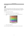
From the Windows Program Manager, do the following to begin using ID Card Designer.
Move the mouse pointer to the Mosaic program group and double-click (press the left
mouse button twice) on the ID Card Designer icon to start up the application.
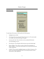
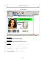
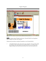
While the application is loading, an ID Card Designer information box is displayed, and
then the Main Window appears.
54
CARD DESIGNER
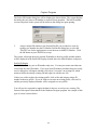
Main Window
After the application is finished starting up (see Start-Up Procedure), the ID Card
Designer Main Window will appear.
ID Card Designer Main Window
The Main Window will hold all ID Card Designer activity. Note that at start-up, only
two headings, File and Help, are showing in the Menu Bar. Also note that two buttons
are showing on the Standard Tool Bar, and one of those, the Open File button, is active,
or available. The other button, Close File, appears gray, meaning that it is not presently
active.
Select the File menu header and select Open from the drop-down menu, or click on the
Open File button in the Standard Tool Bar. The Open Database window appears.
55
CARD DESIGNER
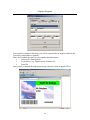
Open Database Window
Selecting the Open command from the File menu in the Main Window causes the Open
Database window to appear.
Open Database Window
From the list box in the window, select the database for which you wish to design or edit
an ID card.
Click the OK button to continue to the Card Selection Window.
56
CARD DESIGNER
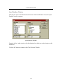
Card Selection Window
After clicking OK in the Open Database window, the Card Selection window will be
displayed.
Card Selection Window
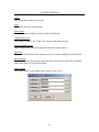
In the Card Selection window, choose from among the following command buttons:
New - to create a new ID card.
Design - to edit an existing ID card. First, highlight your card choice in the list box, then
click on this button.
Delete - to delete an ID card from the list. Highlight the card to be deleted in the list box,
then click on this button.
Edit Description - to edit an existing ID card's description. Highlight your card choice in
the list box before clicking on this button.
Set Default - to set a default ID card to be displayed in the Mosaic Capture/Retrieve
software.
57
CARD DESIGNER
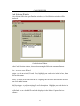
Card Description Window
To open a new card, at the Card Selection window take the following steps.
1.
Click on New in the Card Selection window, and the Card Description window
will be displayed.
Card Description Window
You will assign two identifying descriptions to a new card by typing in the Short and
Long Description fields.
Short Description - An alphanumeric file number, up to 8 characters long, which the
software can use to index and identify your card designs.
Long Description - A text description which helps you to select the correct ID card when
working in the Mosaic design or Capture/Retrieve software.
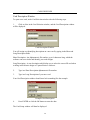
2.
Type in a Short Description alphanumeric file number.
3.
Type in a Long Description of your new card.
Your Card Description window should now look something like the example.
Example Card Description
4.
Press ENTER or click the OK button to enter the data.
The Card Setup window will then be displayed.
58
CARD DESIGNER
Card Setup Window
Once you have typed and entered the Card Description data, the Card Setup window will
be displayed, as shown.
Card Setup Window
The Card Setup window allows you to set or change the basic card parameters of width,
height, margin size, and orientation, and to choose whether or not there will be a
magnetic stripe on the back of the card.
Card Size and Margins
The defaults for width, height, margins and orientation are preset for a standard-sized ID
card printed on a standard card printer. You may not find it necessary to change any of
the width, height, margin settings or orientation if you are issuing a standard wallet-sized
ID with the normal printing margins.
Orientation
If you are issuing a wallet-type ID card, the correct orientation setting is the horizontal, or
Landscape mode. If you are issuing a badge or tag, however, you may wish to change the
card's orientation so that it appears upright by clicking the Portrait button.
59
CARD DESIGNER
Magnetic Stripe
If there will be no magnetic stripe on your card, select the default setting as shown in the
figure, "ID card does not contain a mag stripe". If you do wish to have a mag stripe on
the card, choose whether it is to be ‘Manually determined’, HI-CO or LO-CO by clicking
the appropriate button. Then click the Mag Data button to configure the magnetic stripe
data. See Creating Magnetic Stripe Data.
Smart Card Chip
If there is a ‘chip’ on the ID card, highlight this option and add the appropriate DLL.
When all the setup choices are satisfactory, click on OK to accept, and the Card Designer
window will appear.
NOTE: You can return to the Card Setup window at any time by selecting it from the File
drop-down list in the Main Menu.
60
CARD DESIGNER
Card Designer Window
After accepting the contents of the Card Setup window, the ID Card Designer window is
displayed.
ID Card Designer Window
This window holds all your card design components. The surrounding menus control the
tools for creating card elements and defining, sizing, and formatting these card elements.
In learning to use each of these tools, you will be learning how to create an ID Card.
61
CARD DESIGNER
Main Menu Bar
Main Menu
The Main Menu Bar contains the following menu headings:
File
Edit
View
Draw
Window
Help
Commands in this menu may be executed by clicking with the mouse pointer, or by
pressing key combinations.
To access the File menu, for example, use the mouse pointer to click on the File menu
heading, or press the Alt key plus the 'F' key. A drop-down list will appear showing
commands available under File. Click again with the mouse, or type the underlined letter
in one of the listed commands, to execute it. See drop-down lists illustrated for each
menu heading in the corresponding Help topic.
Shortcut Key combinations are shown, where available, to the right of each command
name in a drop-down list. Once you have learned these combinations, commands can be
accessed directly by typing these key combinations, without the necessity of going to the
Menu Bar.
62
CARD DESIGNER
The File Menu
The File menu contains the following commands.
Open
This command opens a card window from the existing card files.The Shortcut Key
combination is Ctrl + O.
Close
This command closes the active card window.
Save
This command saves your work to a file. The Shortcut Key combination is Ctrl + S.
Save As...
This command saves your work to a new file under another name of your choosing.
Card Setup...
This command recalls the Card Setup window so that you can edit a card's parameters.
See Card Setup Window.
Print...
This command sends the active window's card design to your printer.
Exit
This command ends your ID Card Designer work session and exits the application. The
Shortcut Key combination is Alt + F4.
NOTE: For easier access, some Main Menu Bar commands are duplicated on the
Standard Tool Bar.
63
CARD DESIGNER
The Edit Menu
The Edit menu contains the following commands.
Cut
This command deletes the selected text or object and places it on the clipboard, where it
is available to paste elsewhere. The Shortcut Key combination is Ctrl + X.
Copy
This command places a copy of the selected text or object on the clipboard, where it is
available to paste elsewhere. The Shortcut Key combination is Ctrl + C.
Paste
This command places a copy of the contents of the clipboard onto the workspace. The
Shortcut Key combination is Ctrl + V.
Select All
This command selects all of the contents of the active window file.
Duplicate
This command makes a duplicate of any selected object and places it on the workspace
Pick Up Object Style
This command copies into memory the style of the selected object so that these
formatting characteristics can be applied to another object.
Apply Style
This command applies a previously copied style to another selected object.
64
CARD DESIGNER
The View Menu
The View menu contains the following commands.
Standard Tool Bar
This command shows/hides the Standard Tool Bar.
Format Tool Bar
This command shows/hides the Format Tool Bar.
Status Bar
This command shows/hides the Status Bar.
Grid
This command shows/hides the gridlines on the card image in the card window
workspace.
Grid Divisions.
You may change the number of dots per inch shown in the gridlines on the card
workspace by changing the number in this field. You may either click the + or - buttons
or type a new number to change the setting.
Zoom.
This command controls the size of the card image in the Card Window. It zooms the card
window image in or out for either a more detailed or a more overall view of your card
design.
You may choose an enlargement or reduction setting from the button list, or you may
type a number into the Percent field. You may also increment or decrement the
percentage shown in the Percent window by clicking the + or - buttons to the right of the
field. The Fit to Window button automatically sizes the image to fill the window. If you
change your mind, click the Cancel button.
Once a percent of enlargement or reduction has been selected, click the OK button and
the card image will be altered accordingly, zooming in to magnify the card image or
zooming out for an overall view.
65
CARD DESIGNER
The Draw Menu
The objects, lines, and rectangles placed on the card image to create a card design have
characteristics similar to objects in many popular drawing applications. The draw menu
contains some basic draw commands which will be familiar to you if you have used other
draw programs.
NOTE: Some of these commands are duplicated by buttons on the Standard Tool Bar.
Handles
Any object selected by clicking with your mouse pointer displays a set of handles around
its edges.
Selected Objects Show Handles
These handles may be used to stretch or shrink the object vertically (by clicking and
dragging a top or bottom handle), or horizontally (by clicking and dragging a left or right
side handle), or to resize it (by clicking and dragging a corner handle), or move it (by
placing the mouse pointer over the center of the object [which causes the pointer image to
turn into a small hand] and clicking-and-dragging the object into position).
Group
By using the mouse pointer to drag the dotted line "marquee" around several objects, or
by holding down the Shift key while selecting with the pointer, more than one object on
your card may be selected at a time. When two or more objects in the Card Window are
selected (one set of handles surrounding all), click on the Group command to combine
these objects into a single object for convenience in moving and sizing while maintaining
these objects' distance, position, and general orientation to one another. A group will
have one set of handles surrounding all objects in the group.
66
CARD DESIGNER
Single and Grouped Objects
Selecting the Group command in the case of the example pictured above causes the
selected objects to become one object.
NOTE: To edit text in an object which is a member of a group, you must first Ungroup
the object.
Ungroup
To ungroup objects which have been previously combined into a Group, select the group,
then select the Ungroup command. If other grouped objects exist within the selection,
clicking on Ungroup again will ungroup further smaller groups. After ungrouping,
individual handles again appear on single objects when selected.
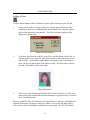
Bring to Front
First, a word about layers: Each object placed on a card design is layered over the object
placed just prior to it. There may be as many layers as there are objects placed on a card.
An object may be moved forward or backward ("up" or "down") in this series of layers.
67
CARD DESIGNER
Layered Objects
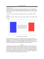
The objects in the figure are layered. The tiger was placed on the card first, the rectangle
second, and the photo most recently. Because of this, the tiger is the back layer, the
rectangle is forward of the tiger, and the photo is currently the front layer. The operator
has clicked on the rectangle to select it.
When an object has other objects partially obscuring it, and you wish to bring it to the
front of the group, select the object and click on the Bring to Front command. The object
immediately appears as the front layer. To bring the rectangle to the front layer in this
example, after selecting it you would click the Bring to Front command, and the card
would then appear as shown below.
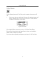
Bring to Front
Send to Back
The quickest, easiest way to send an object to the back of a cluster of objects is by
clicking on the Send to Back command. No matter how many layers are on the card, the
selected object will become the bottom-most, or back, layer. In our example, selecting
the rectangle and choosing the Send to Back command causes the card to appear as the
figure below.
68
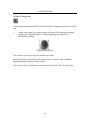
CARD DESIGNER
Send to Back
The selected rectangle is now behind all other card elements.
Bring Forward and Send Backward
There are as many layers as the total number of objects placed on a card. You may want
to re-order these layered objects in a variety of ways. Since you are likely to have many
layers on your card, you need to be able to move objects forward and backward a layer at
a time. You may want to overlap objects, reveal obscured portions of objects by bringing
them forward a few layers, or hide portions of other objects by sending them backward a
few layers. The Bring Forward and Send Backward commands allow you to move
selected objects easily through the card layers, just as you might re-order index cards.
To use these two commands, do the following.
1.
Select an object you wish to re-position.
2.
Click on Bring Forward or Send Backward. Each time the command is given, the
object moves one layer on the card.
Keep in mind that there are as many layers as the total number of card elements, and that
even objects which are not touching each other are on separate and distinct layers. To put
an object behind another object, you may have to choose Send Backward several times if
your card design has a large number of elements, since there may be several other layers
between your selection and the object beneath it.
69
CARD DESIGNER
Align
This powerful command facilitates lining up a number of individual objects, vertically or
horizontally, all at once, without the use of the grid and without operator guesswork. To
use the Align command, first create several objects on the card that you will want to
align.
Unaligned Selected Objects
We would like to align the data headings Hair, Eyes, Ht., and Wt. so that they appear in a
neat row on our card. To accomplish this we do the following:
1.
Select all of the objects by dragging a marquee around them with the mouse
pointer (or by Shift-clicking on each).
2.
Click on the Align command. Another drop-down list will appear with vertical
and horizontal alignment options.
3.
Click on the alignment option that will correctly position your selections, and the
objects are automatically aligned accordingly.
In our example, we chose ‘Middles’, for horizontal alignment of the object centers. The
resulting alignment of the elements, shown still selected, is seen below.
Middle Aligned Objects
To maintain this alignment, we might now combine the objects into a Group (described
above), so that we can move them around on the card as one object, maintaining the
relationship between the components.
70
CARD DESIGNER
Snap to Grid
Another way to align objects on your card is by using Snap to Grid. When you place an
object on your card or move an existing object, you may want the convenience of having
those objects align automatically, by adhering to the gridlines you have chosen for your
card window. When the Snap to Grid command is checked, objects placed on the card
"snap" into alignment with the nearest gridline. This makes it easy to create a neat and
professional-looking card quickly, without the necessity of zooming in to make fine
adjustments of each card element you place.
If you prefer to make finer adjustments than Snap to Grid allows, or if you wish to move
an object off a gridline, uncheck the Snap to Grid command on the drop-down list, and
you can then move objects on the card window pixel by pixel, until you re-check the
command. In either mode, objects will remain where you last placed them.
The Window Menu
This menu heading is a standard Windows "housekeeping" feature in most Windows
applications.
If you have more than one window open in the Card Designer window, you may arrange
them neatly on your screen using either the Cascade or Tile commands. If the windows
are "iconized", use the Arrange Icons command to arrange them neatly across your
window. All open windows are listed under this menu heading, with the active window
checked. If you have overlapping windows open, you can use the Window menu to bring
a desired window to the front, making it the active window.
See your Windows user manual for more details on the manipulation of windows.
71
CARD DESIGNER
Standard Tool Bar
The buttons on the Standard Tool Bar control many of the basic application functions. A
single mouse click executes each command.
Standard Tool Bar
The buttons shown above represent the following commands.
1.
2.
3.
4.
5.
6.
7.
Open
Save
Print
Cut
Copy
Paste
Acquire Style
8. Apply Style
9. Select All
10. Group
11. Ungroup
12. Bring Forward
13. Send Backward
14. Zoom In/Out
Open
Brings up the Open window so that you can open a pre-existing card design to edit.
Save
Saves your card changes to the file on the hard drive.
Print
Sends the active card design to your printer.
Cut
Removes a selected object or text from the card and puts it on the application's clipboard
so that it is available to paste elsewhere.
Copy
Puts a copy of the selected object or text into the clipboard, without deleting it from its
present location, so that the same object or text is available to paste elsewhere.
Paste
Places a copy of the contents of the clipboard on the card.
Acquire Style
Copies the color or other formatting of the object selected when the eye dropper button is
clicked.
72
CARD DESIGNER
Apply Style
Applies a copied color or other formatting from the eye dropper to an object or group of
objects selected when the apply style button is clicked.
Select All
Selects all the objects on a given card without having to drag a marquee around them.
Group
Turns two or more selected objects into one selection, so that the objects within can be
moved or resized together, while maintaining their orientation to one another.
Ungroup
Returns grouped objects to their previous individual components.
Bring Forward
Moves an object one layer closer to the front in relation to all other layers of objects on a
card. Each time an object is selected and the Bring Forward command is given, one
object layer is sent behind the selected object, and the selected object moves one level
closer to the top. This is true whether or not objects are overlapping in your design
window.
Send Backward
Each time Send Backward is clicked, a selected object is sent one layer back in relation to
all other objects on a card.
Zoom In/Out
Enlarges or reduces the active card in the Card Window enabling you to either see your
whole card at once for an overview, or examine your card in detailed close-up for fine
adjustments. When the Zoom button is clicked, the previously illustrated Zoom window
is displayed.
73
CARD DESIGNER
The Format Tool Bar
The Format Tool Bar appears on the Card Designer Window, in the space below the
Standard Tool Bar and above the Tool Palette. This tool bar contains formatting tools
which are specific to the tool selected on the Tool Palette. The Format Tool Bar only
appears when a tool is selected on the Tool Palette which has formatting capabilities.
Whenever a Bar Code object on a card is selected, for example, the Bar Code Format
button will appear in the Format Tool Bar.
Bar Code Format Button
Whenever a Text object is selected on the card image, for example, the Text Formatting
tools appear in the Format Tool Bar.
Text Format Bar
See the discussion of specific Tool Palette tools for further explanation of Format Bar
tools.
74
CARD DESIGNER
The Status Bar
The Status Bar, running along the bottom of the Card Designer Window, contains
information about the application, most importantly the coordinates of the tip of the
mouse pointer on the card grid. Using coordinates, you can place or align objects with
great precision.
Also indicated in the Status Bar is the object tool selected and the condition of the Caps
and NumLock keys.
Coordinates / Dimensions
Status Bar pointer coordinates and object dimensions are illustrated below.
Object/Coordinates Status
Key Indicators
The Status Bar key indicators display is illustrated below.
Key Indicators
75
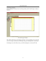
CARD DESIGNER
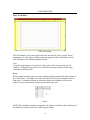
The Card Window
The Card Window
The Card Window is the canvas upon which ID card designs will be created. When
beginning a new card design, a blank card image appears in the Card Window, which
also encompasses the following helpful features:
Grid
A dotted-line grid appears over the face of the card to allow easier placing of card
elements. This grid can be turned on or off and its increments can be re-sized using
commands in the Menu Bar.
Rulers
Rulers marked in inches appear vertically and horizontally along the left and top edges of
the Card Window. The upper left corner of the ID card is always positioned at zero on
both rulers. Coordinate markers on both rulers follow the coordinates of the mouse
pointer for easy measurement of objects positioned on the card.
Rulers
NOTE: The coordinates markers correspond to the pointer coordinates values displayed in
the Status Bar at the bottom of the Card Designer window.
76
CARD DESIGNER
Scroll Bars
The scroll bars on the Card Window, shown in the next illustration, are useful
1) when you have created a larger-than-standard-sized card, or 2) when using the Zoom
feature for a closer look at your card. In either case, the scroll bars are used to move
around a card image when it is bigger than the available window space, so that you can
view any portion of it. See your Windows manual if necessary for further information on
how to operate scroll bars.
To move around using the scroll bars, you may:
Scroll Bars
Maximize/Minimize Buttons
The Minimize/Maximize buttons, located in the upper right corner of the Card Window,
are shown below.
Minimize/Maximize Buttons
When working with one new card, it is recommended to click the Maximize button in the
upper right corner of the Card Window. This will enlarge your card image to fill the
available screen and make working in it easier.
The Minimize button may be used to "iconize" a card window, or shrink it down to icon
size, so that you can store it on the Main Window for future use or reference while
working on another card design. You may have several card windows open, or iconized,
in the Card Designer Window.
See your Windows manual if you need more information on the Minimize/Maximize
buttons.
77
CARD DESIGNER
The Tool Palette
The Tool Palette enables you to place all the major ID card elements as you build a new
two-sided card by simply pointing, clicking and dragging. Each data element placed on
the card image will be represented by a placeholder graphic, to allow you to see as
accurately as possible what your card will look like as you design it.
Click on any button in the illustration below to go to the discussion of that function.
The Tool Palette
The Tool Palette contains the following tools.
Front/Back Buttons
Mouse Pointer Button
Create Button
Photo Button
Signature Button
Fingerprint Button
Link Button
Bar Code Button
Clip Art Button
Text Button
Rectangle Button
Foreground Fill Button
Background Fill Button
Rotate Button
78
CARD DESIGNER
The Front/Back Buttons
The Front and Back buttons on the Tool Palette not only control which side of the card
you are working on, they also allow you to see at a glance which side of the card is
displayed. When the Front button is depressed, as in the figure above, you are viewing
the front of your ID card in the Card Window.
79
CARD DESIGNER
The Mouse Pointer Button
Click the Mouse Pointer Arrow button on the Tool Palette to use the mouse pointer in its
usual mode, for pointing, clicking, selecting, and dragging in your Card Window. The
elements which you create on your ID card, such as rectangle, photo, signature and
fingerprint, all behave as "draw objects", meaning that, as in many popular drawing
programs, they can be selected and resized, repositioned and rotated without losing image
integrity. See the Draw Menu Help topic for more about draw objects.
Dragging
This manipulation is done by using the mouse pointer to select objects or grasp the
"handles" which appear at the edges of each object when it is selected. By clicking on
these handles and holding down the mouse button, you can drag an object to a larger or
smaller size, and in the case of the rectangle, change its shape as needed, from a thin line
of ribbon to a square, bar, box or rectangle.
Dragging with Handles
80
CARD DESIGNER
Creating an ID Card
ID cards are created in ID Card Designer by adding, positioning and formatting elements
which are available on the Tool Palette. Each tool on the Tool Palette adds a specific
element to your card image as you create an ID card design.
These tools not only can be mastered easily by the beginning user, but each has many
configurable formatting variables for the advanced user, so that anyone can create a wide
variety of professional, secure ID card designs without the need for programming or
software development expertise.
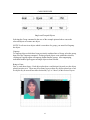
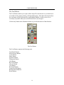
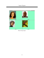
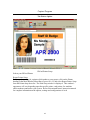
Each card element uses an example as a placeholder so that you can see as accurately as
possible while you are working what your finished card will look like. An example of a
finished card design with placeholders is shown below.
Finished ID Card with Placeholders
81
CARD DESIGNER
Adding a Photo
Click the Photo button on the Tool Palette to place a photo element on your ID card.
1.
Put the cursor on the card image where you want the upper left corner of the
cardholder's photo to be, and holding the mouse button down, drag out a photo
object of the desired size and position. The Photo Selection window will be
displayed as shown below.
Photo Selection Window
2.
If you have one photo for each file, select OK to use the default, Front View. If
you have profile views stored as well, click a button to choose the desired view
and click OK. A placeholder sample photo will appear on your card design to
show you the size and position of the photo element. The photo object remains
selected, with handles visible at the edges.
Photo Placeholder
3.
Click on one of the handles and drag the object to the desired size, or click in the
center of the photo and hold the mouse button down to grasp the object in order to
move it around the card.
When an actual ID card is issued later by the Capture/Retrieve software, each applicant's
captured photo image will appear in the space which is reserved by this photo object.
You are now ready to add another card element to your design. See The Tool Palette.
82
CARD DESIGNER
Adding a Signature
Click the Signature button on the Tool Palette to place a signature element on your ID
card.
1.
Put the cursor where you want the upper left corner of the signature to appear, and
drag out a signature object of the correct size and location. A sample signature
will appear as a placeholder, as shown below.
Signature Placeholder
After creating the object, you can move or resize it. See Mouse Pointer Button.
When an ID card is issued later by the Capture/Retrieve software, each cardholder's
signature image will appear in this position.
You are now ready to add another card element to your design. See The Tool Palette.
83
CARD DESIGNER
Adding a Fingerprint
Click the Fingerprint button on the Tool Palette to place a fingerprint element on your ID
card.
1.
Put the cursor where you want the upper left corner of the fingerprint to appear,
and drag out a fingerprint object. A sample fingerprint will appear as a
placeholder, as shown.
Fingerprint Placeholder
You can move or resize the object as described previously.
When an ID card is issued later by the Capture/Retrieve software, each cardholder's
fingerprint image will appear in this location.
You are now ready to add another card element to your design. See The Tool Palette.
84
CARD DESIGNER
Adding a Link
Click the Link button on the Tool Palette to place an element of linked demographic data
from the database onto your ID card.
1.
Put the cursor where you want the upper left corner of the Link object to appear,
and drag out an object. The Data Field Contents window will then be displayed.
2.
3.
4.
5.
Highlight the fields you wish to add. This will appear in the selection line.
You can format this field by highlighting the format option.
When you are satisfied with the data field contents depress the ‘Add’ Button.
click OK.
The data field titles, in brackets, appear on the card where the cardholder data will appear
on the finished cards.
6.
Use the Link tool to repeat this procedure to put additional data fields on your
card as needed.
See Linked Data Field Formatting to learn how to enter and format data fields.
You are now ready to add another card element to your design. See The Tool Palette.
85
CARD DESIGNER
Adding a Bar Code
Click the Bar Code button on the Tool Palette to place a bar code element on your ID
card.
1.
By clicking and dragging on the card image, use the pointer to define the space to
be occupied by the bar code. Upon finishing the bar code placement and
releasing the mouse button, the Bar Code window will be displayed.
Bar Code Window
2.
Select and configure the type of bar code you wish to insert by making selections
in the Symbology and Options boxes. See your bar code reader's instruction
manual for details on these settings.
3.
Click the Edit Contents button, and the Data Field window is displayed. See
Linked Data Field Formatting for further discussion.
4.
Enter the necessary data field information in the Contents window. Click OK
when finished.
5.
Click the OK button at the Bar Code window to accept your bar code data.
6.
Click the Sample Data button, and the Sample Data window is displayed as
shown below.
86
CARD DESIGNER
Bar Code Sample Data Window
7.
Type in a text or number string of the same length as the expected data in your bar code. Click the
OK button to accept.
A placeholder bar code graphic will appear so that you can accurately size and position your bar code on
the new card design.
When an ID card is issued later by the Capture/Retrieve software, the bar code object will contain specific
data for each cardholder.
NOTE: Whenever a Bar Code object on a card is selected, the Bar Code Formatting button will appear in
the Format Bar.
Clicking on this button re-displays the Bar Code window, allowing you to edit the information in the
selected bar code element.
You are now ready to add another card element to your design. See The Tool Palette.
87
CARD DESIGNER
Adding Clip Art
Click the Clip Art button on the Tool Palette to place a piece of artwork of your choosing,
such as your company logo, on the ID card.
1.
Put the cursor on the card and drag out an object of the approximate size and
position for the desired artwork.
An Open dialog box will appear, with a scrolling list of the files on the current drive.
2.
Select any piece of bitmap artwork from your hard drive or a floppy disk to be
imported onto your ID card. Click the OK button in the Open window.
The art will display immediately, and it can then be resized and positioned.
Whenever a Clip Art object is selected, the Format Bitmap button appears in the Format
Bar, and the Format Bitmap Window may be accessed.
You are now ready to add another card element to your design. See The Tool Palette.
88
CARD DESIGNER
Adding Text
Click the "T" button on the Tool Palette to create text on your ID card. Text created
using the Text tool does not identify a data field. This text will print, exactly as you
typed and formatted it, on every finished ID card. You might use this tool to place a title
such as "Department of Corrections" on your card, or an identifying header for
information such as "ID Number:", or a notice such as "This ID card may not be altered
or reproduced".
1.
Put the cursor where you want the upper left corner of the Text object to appear,
and drag out an object. The Edit Text window will then be displayed.
Edit Text Window
2.
Type the desired text into the Edit Text window.
3.
If you need more than one line of text, press Ctrl + ENTER to create each
additional line. Press the Cancel button to exit the window without entering text.
Use the scroll bar to the right of the text window to review several lines of text.
4.
When finished, you may press ENTER to close the window and place the text
object onto the card.
You may then format the text. See Text Formatting.
You are now ready to add another card element to your design. See The Tool Palette.
89
CARD DESIGNER
Text Formatting
Whenever the Text Tool is selected on the Tool Palette, a row of text formatting buttons
appear in the Card Designer window's Format Tool Bar.
Text Format Bar
To add or change formatting, do the following.
1.
Select the text object so that the "handles" are visible. The text formatting tools
will appear in the Format Tool Bar.
2.
Format the text using the buttons on the Format Tool Bar.
Text created using the Text tool will appear, exactly as typed and formatted, on every
printed card. You might use this tool to place a title such as "Department of Corrections"
on your card, or an identifying header for information such as "ID Number:", or a notice
such as "This ID card may not be altered or reproduced".
90
CARD DESIGNER
Adding a Rectangle
Click the Rectangle button on the Tool Palette to place any size and shape of solid
rectangular object (with square corners) on your ID card. The rectangle object will
appear, complete with "handles," so that it can be selected, moved, sized, and colored in
any way you choose.
You may create vertical and horizontal LINES using this tool, as well as solid colored
backgrounds, bars, stripes, boxes, borders, etc.
To create a Rectangle object, do the following.
1.
Put the cursor where you want to start drawing, and drag out a Rectangle object.
The object will appear selected (with handles).
2.
Use the handles to re-shape the object as you wish by dragging. You can create
any shape with square corners.
3.
Use the Background Fill command to color the object as desired.
Rectangles can be sized and positioned to place lines, ribbons or stripes on a card, or to
add shadow effects or backdrops to other objects like photos and artwork. Its uses are
limited only by the card designer's imagination.
Because objects inserted onto a card design are positioned on the card in successive
layers, you can then use the Draw Menu command in the Main Menu Bar to position
other objects or text over or under the rectangle you have created.
You are now ready to add another card element to your design. See The Tool Palette.
91
CARD DESIGNER
Foreground Fill
Click the Foreground Fill button on the Tool Palette to choose the color of foreground
objects like text, signatures or bar codes. Make the signature appear to have been signed
in red ink, for example, or make text white so that it can be easily read over a darker
background.
To use Foreground Fill, do the following.
1.
Select the object to which you wish to add or change color.
2.
Click on the Foreground Fill Tool button. The Foreground Fill Palette will
appear.
Foreground Fill Palette
3.
Select a color by clicking on it.
See the Format Bitmap Window Help topic for more details on working with colors.
92
CARD DESIGNER
Background Fill
Click the Background Fill Tool on the Tool Palette to choose the color of the background
in a draw object or text box. For example, rectangles can be colored in any available
shade using this tool.
To use the Background Fill Tool, do the following.
1.
Select the object to which you wish to add or change color.
2.
Click on the Background Fill Tool. The Background Fill Palette will appear, as
shown below.
Background Fill Palette
3.
Select a color by clicking on it.
See the Format Bitmap Window Help topic for more details on working with colors.
93
CARD DESIGNER
Rotating an Object
Click the Rotate button to turn an object in 90 degree increments. Pressing the Rotate
button on the Tool Palette causes drop-down buttons to appear which allow you to choose
any of four different orientations, as shown.
Rotation Drop-down Buttons
To use the Rotation Tool, do the following.
1.
Select the object that you wish to rotate.
2.
Click the desired rotation icon. The object jumps to its new orientation on the
card.
94
CARD DESIGNER
Linked Data Field Formatting
Whenever you place a linked object on your new card design, the Data Field Contents
window will be displayed.
Data Field Contents Window
To create a linked data object, do the following.
1.
Type into the Contents window the data field(s) you want to be displayed.
Select from among the data fields which you have previously created in Database
Designer. Format your entries to display the data on the finished card as you would like
it to appear. (You will enter and format Mag Stripe data in exactly the same way.)
The Available Fields window lists the data field names you created in Database Designer.
Scroll through the list to familiarize yourself with the available data choices. The Field
Formatting window will reveal any available data formatting options for a field when
selected on the Available Fields list.
95
CARD DESIGNER
A Note Regarding the Magnetic Stripe
The data fields in Mag Stripe Tracks are formatted exactly the same way as is being
described here. See the Help topic on Creating Magnetic Stripe Data for a further
discussion of that function, and when entering Mag Stripe Data, refer to this Help topic
for the description of data fields entry and formatting.
Placing Data Fields
As an example of a Linked Data Field object, let's place a name and address data field on
a card design. For this example, we assume that in Database Designer, you created fields
for all the needed elements of a name and address, including First Name and Last Name,
City, State and Zip, and at least two lines for address material, which we will call
Address1 and Address2. Address1 and Address2 might be any combination of company
name, suite or apartment number, a P.O. box, street address or any other address data
item.
Using Brackets
So that Mosaic can recognize these titles as Links (where card applicant information is to
be inserted) we enclose them in "curly" brackets:
{First Name}
{Last Name}
{Address1}
{Address2}
{City}
{State}
.....and so on.
If you have created additional data fields, like Middle Name or Middle Initial, you may
wish to include these in your ID card's name and address data as well. Some card
applicants will no doubt have information for both Address1 and Address2, and others
will not. If you include both data fields, Mosaic will close up the empty space whenever
the extra line is not used.
How do we enter these fields in the Data Field Contents window so that cardholder
information will appear as desired on the finished cards? See the topics Creating Data
Field Contents, and Syntax.
96
CARD DESIGNER
Creating Data Field Contents
As we said in the topic Linked Data Field Formatting, each data field you enter in the
Data Field Contents window must be enclosed in brackets. The brackets are necessary to
set off your data fields from each other and from plain text. You want the ID Card
Designer application to replace your data field names in the Contents window with an
actual data entry later, but still allow you to include commas, periods, or other text in the
Contents window as you need them to format your information for a pleasing and orderly
card design.
The basic format for any data field entry in the Contents window is:
{Field Name}
Therefore, the proper format for a Name and Address object, for example, using the field
names you assigned in Database Designer, might look like this:
{First Name} {Last Name}
{Address1}
{Address2}
{City}, {State} {Zip}
Notice that each field name is enclosed in brackets, that there is a space between data
fields (because there needs to be a space between words), and a comma and space
between the City and State fields. Although it is not visible, there is a carriage return at
the end of each line, as well.
The spaces and the comma are outside of the brackets. They, and anything else outside
of brackets, will appear exactly as typed on every issued ID card. A printed card entry
based on the data object described above would look like this:
Joe Dokes
Apartment 414
11008 Buena Vista Street
Burbank, Ca 91523
If you were to omit the spaces between bracketed items, the name entry would appear as
"JoeDokes". If you were to omit the comma and spaces, the City and State entries would
appear as "BurbankCa". By typing spaces, commas and periods between bracketed
items, you configure linked data objects in the text exactly as you would like to see the
data on the finished cards.
Formatting Carried Over from Database Designer
If any formatting characteristics were applied to a given data field when the field was
created in Database Designer, such as All Caps, Bold, or Italics, these characteristics will
automatically appear on the finished ID cards, if no other action is taken.
97
CARD DESIGNER
If you wish to OVERRIDE those settings, OR if formatting was NOT applied in
Database Designer, OR if you wish to add additional formatting at this time, certain
format commands may be added to any data field after entering it here in the Data Field
Contents window.
To learn how to enter these special format commands, see the topic Syntax.
Syntax
When entering data fields, a common syntax discipline is used, so that Mosaic can
correctly link, format and print the data on each individual's finished card.
NOTE: This same formatting syntax applies to fields entered as Magnetic Track data.
Basic Syntax for Entering or Formatting Data
As discussed in the topic Linked Data Field Formatting, the basic "syntax" for entering a
linked data field is the Data Field Name in brackets, as follows:
{Last Name}
Modifiers
To add formatting instructions to a data field, you will use a comma followed by a space
and then a modifier, or a series of modifiers, then another space, and the closing curly
bracket, as illustrated:
{Last Name, modifier }
Keep in mind that modifiers are optional format commands. A Linked object can be
created on an ID card without any modifiers at all. When modifiers are used, always start
with a comma after the data field name.
When using more than one modifier, use a space between them, and a space after the last
modifier before the closing curly bracket, as follows:
{Last Name, modifier modifier modifier }
Examples of data fields with modifiers are as follows:
{Sex, LOOKUP }
{State, RAW UPPERCASE }
{Address, CENTER (25) }
1{ID, LOWERCASE }
See Valid Format Commands for the set of valid format modifiers for ID Card Designer.
98
CARD DESIGNER
Valid Format Commands
Valid modifier syntax when creating Linked Data Field Formatting are as follows.
UPPERCASE
Use this command to force the text in the data field to upper case, regardless of any
formatting in Database Designer.
LOWERCASE
Use this command to force the text in the data field to lower case, regardless of any
formatting in Database Designer.
LOOKUP
Use this command to force the entry in the data field to be the Lookup Table entry from
Database Designer, rather than the data field code itself. (See Database Designer online
help for further explanation of Lookup Tables and field codes and abbreviations.)
Example:
{Sex} = M or F
{Sex, LOOKUP } = Male or Female
LEFT ( n )
Use this command to force the text in the data field to be left justified. This command
requires an additional modifier ( n ) in parentheses indicating the number of spaces to be
allowed for the field. Therefore, the Left modifier with an allotment of 24 characters,
when typed into a data field entry, looks like this:
{Last Name, LEFT ( 24 ) }
CENTER ( n )
Use this command to force the text in the data field to be centered. This command
requires the ( n ) modifier described above in the discussion of the LEFT modifier, and is
used exactly the same way.
RIGHT ( n )
Use this command to force the text in the data field to be right justified. This command
requires the ( n ) modifier described above in the discussion of the LEFT modifier, and is
used exactly the same way.
RAW
Use this command to force the text in the data field to ignore any formatting which might
have been attached to it in Database Designer. Such text will appear unformatted, or raw,
in the Linked object.
99
CARD DESIGNER
FORMAT ("mask ")
Use this command to force the text in the data field to adopt a mask, or template, which
you assign to it. Simply type the command FORMAT followed by the mask, inside
double quotation marks, in parentheses.
A mask is simply another kind of formatting discipline for specific types of information,
like dates or telephone numbers. The mask "999-999-9999" is valid for phone numbers,
for example, having the correct number of digits to force a telephone number string like
2195551212 to become a more sensible 219-555-1212 on a printed ID card.
Examples of valid format masks in ID Card Designer data fields include the following.
Note that double quotation marks inside parentheses (" ") are always used to set off the
contents of the mask from the formatting codes surrounding it.
{Social Security, FORMAT ("999-99-9999") }
{Telephone, FORMAT ("(999) 999-9999") }
{Birth Date, FORMAT ("mm/dd/yy") }
{Birth Date, FORMAT ("mmmm dd, yyyy") }
{Birth Date, FORMAT ("mmm dd, yyyy") UPPERCASE }
Dates are masked using the standard 'm', 'd' and 'y' placeholders. Only certain date mask
choices are valid. The valid format options using 'm', 'd' and 'y' are as follows.
Date
Characters
Description
m
Month without zero fill
mm Month with zero fill
mmm Three character abbreviation
mmmm
Full month name
d
Day without zero fill
dd
Day with zero fill
yy
Year excluding century
yyyy Year including century
100
CARD DESIGNER
Wild Card Characters
Masks may be created using any of the following special 'wild card' characters. All other
characters typed into a mask are assumed by the software to be constant placeholders,
such as '-' or '/'. The valid wild card characters are:
Character
X
9
A
N
U
L
H
Legal Characters
Any ASCII character
Any numeric character 0 to 9, or decimal point
Alphabetic characters A-Z, or a-z
Alphanumeric characters, combination of types A and 9
Upper case alphabetic characters A-Z only
Lower case alphabetic characters a-z only
Hexadecimal digits 0-9, A-F, a-f
Each wild card character in the mask directly holds a place for one character from the
data to be displayed. For example, everyone's Social Security number has nine digits in
it. Any mask for a Social Security number, therefore, would need nine wild card
characters to properly format the database entry; i.e., "999-99-9999" is a proper mask for
a Social Security number because it holds exactly the right number of places for the
entire Social Security number to print.
Similarly, a telephone number in the United States has a 3-digit area code followed by a
7-digit local number. Therefore, acceptable masks for a U.S. area code and phone
number data entry would include "(999) 999-9999" as well as "999-999-9999", and also
"999/999-9999".
101
CARD DESIGNER
Format Bitmap
When working with the bitmap objects Photo, Signature, Fingerprint or Clip Art, the
Format Bitmap button is the only formatting button which will appear in the Format Tool
Bar.
Clicking the Format Bitmap Button displays the Format Bitmap window.
Format Bitmap Window
The Format Bitmap window allows you to control various characteristics of a given
bitmap object.
Information
The bitmap file name is shown along with the image height and width in pixels, and the
color depth in bits, for the benefit of more advanced users.
102
CARD DESIGNER
Link to File
NOTE: This function should not be confused with the adding of a Linked Data Field in
ID Card Designer. See Linked Data Field Formatting for discussion of that function.
The Link to File checkbox only appears in the Format Bitmap window when a draw
object is selected which can be linked, rather than copied, to your card image file. Its
purpose is to allow you to keep the .dbl file from growing very large by enabling you to
insert a graphic onto your card design without actually saving a copy into your card
image file.
When the box is checked, a bitmap object which you place on your card design, such as a
company logo or a piece of clip art, is not copied into the card image file, but rather a link
is established between the artwork file on your hard drive and the card image. The two
files remain separate on your Mosaic system. The advantage of this method of adding a
graphic to your ID card is that the card image file is much smaller and more efficient to
work with. Any time the card image is displayed, the link causes the artwork to appear,
even though it is a separate file on your computer.
When the Link to File box is not checked, a copy of the bitmap artwork is saved into the
card design file and embedded within it. The .dbl file will become larger by the size of
the graphic file saved into it. The advantage of this method is that if you need to
transport the database files from one office to another on diskette, this can be done
without worrying that linked artwork is being left behind in another directory on the
original computer. Similarly, a linked artwork file might be inadvertently deleted or
moved from its location on the hard drive, so that the card image file could no longer
access it, whereas artwork embedded in the card image file cannot be misplaced.
Keep Aspect Ratio
The aspect ratio is the proportion of height and width in an image. When clicking and
dragging the handles on an object such as a photo to enlarge or reduce it, it is often
important that the relationship of height and width remains the same so that the photo
does not become stretched or distorted.
When the Keep Aspect Ratio box is checked in the Format Bitmap window, a selected
object will maintain its proportion when it is dragged and resized.
When the box is not checked, an object can be stretched, squeezed, or distorted as its
handles are dragged with the mouse pointer.
103
CARD DESIGNER
Grayscale
When the Grayscale checkbox is checked in the Format Bitmap window, the selected
bitmap image will appear as a grayscale image rather than as a color image.
When the Grayscale box is not checked, the image will maintain its original color
attributes.
Ghost
The Ghost checkbox in the Format Bitmap window controls a security feature which
allows a copy of an object such as a photograph to be repeated as the backdrop for other
data elements on a card. It is much more difficult to falsify an ID card when a "ghost" of
the ID photograph is repeated under the demographic data, for example. If the photo on a
card is falsified, the ghost photo will no longer match. If the demographic data is erased
or altered, the ghost photo will be defaced.
Other uses of Ghosting include the following:
1.
It enables you to place artwork under text, signature or other information while
allowing that data to remain legible in the foreground.
2.
It enables you to create a watermark effect on your document.
To use the Ghost feature, do the following.
1.
Place a second copy of the photo object, or any clip art object, onto your card
image.
2.
Use the Send Backward command if necessary to arrange the bitmap object under
the foreground data.
3.
With the object still selected, click the Format Bitmap button to open the Format
Bitmap window.
4.
Check the Ghost checkbox.
5.
Enter a percentage of ghosting for the image. Adjust this percentage until the
desired visual effect is achieved.
Text, signature, or other elements may be placed over the ghost image on the card so that
the ghost image appears behind them. You may need to render the background of
overlapping objects transparent to allow the background artwork to show through. See
the Help topic Transparency to learn how to do this.
If you have placed a ghost photo image, when cards are produced, both photo objects will
display the cardholder's image.
104
CARD DESIGNER
Use of the Ghost Image
Transparency
The transparency feature in the Format Bitmap window is used to cause certain colors in
a bitmap object to become transparent. One purpose of transparency is to clean up a
spotty or dirty image. Another is to allow underlying elements or images to be visible
through it.
To use Transparency, do the following.
1.
Select a color or color range to become transparent. The default color in the
transparency color field is white, which comprises the background in most black
and white bitmap images.
2.
Check the Transparency checkbox.
The white background in a selected black and white bitmap image becomes invisible.
For example, after a signature element is placed on your card, clicking on the
Transparency checkbox and selecting the color white renders the white background fill
portion of the Signature object transparent, so that only the signature image itself is
visible. This image can then be placed to overlap other card elements, such as a ghost
photo or a colored rectangle, without obscuring everything underneath.
The transparency function provided by ID Card Designer can do much more than simply
remove white fill from signature or fingerprint images. By removing specific shades of
color, it can sharpen and clean up images. It can make any one of sixteen million colors,
or a range of color shadings, invisible in a photo or clip art object.
105
CARD DESIGNER
It does this by means of a subset of color controls under the Transparency checkbox
which includes the Color Tolerance Box, the Color Field drop-down menu, and the Color
Window. To learn the use of these controls, see the topic Color Transparency.
Color Transparency
In the figure below, the subset of color controls for Transparency is reached from the
Color Field drop-down list button and the Color Tolerance settings box inside the Format
Bitmap window.
Transparency Controls
These functions may be described as follows:
1.
Color Tolerances - For cleaner removal of the stipulated color, tolerances for the
primary color components Red, Green and Blue are set to a default of + or - 5, but
may be set to any number between + or - 1 and + or - 255. This allows slight
color shading differentiations to be included also. You may increase or decrease
tolerances for each primary color separately, according to specific needs for
cleaning up, sharpening, or removing color shades from your images.
2.
Color Field - Next to the Transparency checkbox is a field showing the color to be
affected by the operation. The default color, white, is handy when you wish to
remove the fill in a signature image, fingerprint image or bar code image. To
choose a color other than the default, click on the field's arrow button to reveal the
Color Field Palette, shown below.
Color Field Palette
If this color palette still does not provide adequate choice in creating and working with
color, click the Other Color button, and the Color Window is displayed.
106
CARD DESIGNER
Color Window
The Color Window offers the choice of up to 16 million shades of color, which can be
selected directly, or created by adjusting the values of light/dark, hue, saturation, and
luminescence. You may directly adjust the values of the primaries Red, Blue and Green
numerically.
To use the Color Window, do the following.
1.
Select an object on your card whose color you wish to change.
2.
Click in the Color Pool on a color you want to use.
3.
Click in the Light/Dark bar to select the shading. The color then appears in the
Color/Solid window, and the corresponding numerical values are displayed.
4.
Adjust any of the values shown as desired.
5.
Click the OK button to apply the color to your selected object.
NOTE: Click the Add to Custom Colors button to put a new color from the Color/Solid
window into the custom colors palette.
107
CARD DESIGNER
Creating Magnetic Stripe Data
Mag Stripe data can only be added if a Magnetic Stripe has been chosen in the Card
Setup Window window. This window is displayed when a new card is created. You can
also access the Card Setup Window as follows.
1.
Select File from the Main Menu Bar and select Card Setup from the File dropdown list.
2.
Select the type of Mag Stripe.
Mag Stripe Setup Options
3.
Click the Mag Data button. The Mag Stripe Data window is shown.
Mag Stripe Data Window
108
CARD DESIGNER
4.
Enter the necessary data fields in the box for Track 1. Repeat for Tracks 2 and 3
if needed. Scroll through the list of available data fields from Database Designer
to refresh your memory as needed.
NOTE: See the discussion of data fields formatting in the Help topic Linked Data Field
Formatting for instructions regarding data syntax for the Track 1, Track 2, and Track 3
Data boxes.
Reviewing and Saving a New ID Card Design
1.
Click the Save command on the File drop-down list to save a new ID Card design
when it is finished.
You may save a new design to the .dbl file and access it later from the IDS
Capture/Retrieve software. You may have as many card designs as you wish. All will be
available in the Capture/Retrieve application once they have been saved in ID Card
Designer.
2.
Choose the Print command from the File drop-down list to print a hard copy of a
card design to a paper printer.
Exit Procedure
To Exit ID Card Designer after saving any finished ID Card designs, simply choose Exit
from the File menu.
If you have not saved a card design, you will be given the opportunity to save it before
the application shuts down.
After exiting ID Card Designer, you will be returned to the Windows Program Manager's
IDS software group.
109
Capture Program
Introduction/Overview
The Mosaic Capture/Retrieve application allows you to perform the following functions:
·
You can create thousands of personal profile entries to your database.
·
You can add applicants' photographs to personal profiles and save the entries to
your database. With optional equipment you can add signatures and/or
fingerprints as well.
·
You can retrieve profiles at any time to add data, edit and modify information and
delete entries.
·
You can produce badges and ID cards, as well as a wide variety of reports. You
can print IDs to a card printer, report printer, or image file as needed.
110
Capture Program
Main Functions
The main IDS Capture/Retrieve functions are as follows.
·
·
·
·
·
·
·
Create
Retrieve
View
Print
Capture
Edit
Reports
Create
The Create function allows you to create a Personal Profile for a new applicant, to
assign an ID number and enter all the necessary profile information for that
applicant, and then to capture the applicant's photo image and save it to the same
profile in a database which you have designed.
Retrieve
The Retrieve function allows you to call up an existing Personal Profile by ID
number, last name, or other user-designated field of information in order to view
existing profiles and to change or update profiles as needed.
View
The View function enables you to display the photo, badge, or ID card of any
person who has an existing Personal Profile.
Note: On Mosaic systems which include the optional signature and/or fingerprint
capabilities, View also allows the display of signature and fingerprint images.
Print
The Print function enables you to print out a photo image, badge or ID card.
111
Capture Program
Capture
The Capture function allows you to capture an applicant's photo and save it with
that person's Personal Profile, and to recapture a photo for an existing profile.
Note: On Mosaic systems with the optional signature tablet or fingerprint scanner,
Capture also enables you to record and save a signature and/or fingerprint image
to the applicant's profile.
Edit
The Edit function allows you to call up an existing Personal Profile, edit the
profile data, and save the edited profile.
Reports
The Reports function allows you to send data reports and audit logs about
Capture/Retrieve activity to your printer.
112
Capture Program
Commands
The Capture/Retrieve application works within a Windows environment. Functions are
performed by choosing a command, usually issued from the keyboard or mouse, that tells
the application to carry out a particular procedure.
You may give a command by:
·
Using the left-hand mouse button to click a Quickbutton on your screen.
·
Using the up or down cursor keys to move the highlight bar on a menu list to the
desired function, and then pressing the ENTER Key.
·
Pressing a Function Key (F1-F12).
·
Using Shortcut Keys.
Use the Cancel button to exit from a screen and return to the previous menu.
Note: For more information on using a Windows program, refer to the Microsoft
Windows user's guide.
113
Capture Program
Login Procedure
Once the Capture/Retrieve application has finished starting up (see Daily Startup
Procedure), the Login window will be displayed.
Login Window
1.
Type in your assigned User Name or select it from the drop-down list. Press
ENTER to move to the Password field.
Note: The default user names are User, Super, and Maint. New account names and
passwords should be created and assigned. New user names will appear in the dropdown list.
2.
Enter your assigned password. Asterisks will appear in place of your password,
as shown in the figure, so that others cannot see it as it is entered.
3.
Click on OK or press ENTER to continue. You may also click Shutdown to exit
the application, or click Help if you have a question.
Once the User Name and Password are successfully entered, the Capture/Retrieve Main
Window will appear, and you are ready to begin working.
114
Capture Program
The File Option
Run Program
Allows you to run the ‘Notepad’ program.
Select Source
Select Twain Source feature disabled after version 1.23.
Scan Pages
Scanning Multiple pages feature disabled after Version 1.23.
Save Image
Allows you to save the image as a file to your hard disk.
Open Configuration
Allows you to change to a different configuration
115
Capture Program
Change Password
Allows you to change your own password.
Lock
If you wish to leave your system unattended for a period of time without shutting down
the computer, you can lock your system.
EXIT
116
Capture Program
The Badge Option
Create
You must assign a unique ID number and create a Personal Profile for each applicant
before a badge or ID card can be produced.
Follow these procedures to assign an ID number to a new Personal Profile.
1.
At the Main Window menu, choose the Create command. You may do this either
by clicking on the Create button in the Quickbutton Bar, or by clicking on the
Badge heading in the Menu Bar and selecting Create from the drop-down list.
117
Capture Program
The Select ID Number dialog box will be displayed as shown below. The system displays
this dialog box any time an ID number is required for an operation. The last ID number
accessed anywhere in the system will be shown in the dialog box upon opening.
2.
Assign a unique ID number to the Personal Profile you are about to create by
typing a new number into the ID Number field in this dialog box or select the
‘Next ID’ box for the application to create the next available ID Number. Click
the OK button or press ENTER to accept.
The system will assign the newly entered ID number to the new profile and this number
will be displayed in the Profile ID Display (located above the Main Window workspace).
Profile ID Display
WARNING: You may use an ID number only once. You may not create more than one
record with the same ID number. If you type in an ID number which has been previously
used, a dialog box will inquire whether you wish to "overwrite" an existing file, which
means to delete the already existing file and replace it with the new file.
Unless you wish to replace the existing profile, click on No and assign a unique ID
number to the new profile. If you do wish to overwrite an existing profile, click on Yes
and the previously displayed number will be assigned to a new profile.
You will now be requested to supply the data for the new record you are creating. The
format of this input is determined via the Database Designer program. An example of this
type of screen is shown below.
118
Capture Program
Once you have completed this stage, you will be requested for an image to attach to the
record for a photo and/or a signature.
There are 3 methods by which you can capture this information.
1.
Camera via a frame grabber.
2.
Twain Source (e.g. Digital camera, Scanner etc)
3.
From File.
Once you have captured the appropriate images, the next screen to appear will be:
119
CAPTURE PROGRAM
Retrieve Card
If you wish to display an applicant's profile but do not know the applicant's ID number, at
the Select ID Number dialog box click on the Search button. The Profile Search window
is then displayed as shown below.
Profile Search Window
Profile Search allows you to search all the Personal Profiles in your database by ID
number or by Secondary Sorts you previously created using the Database Designer.
When the Profile Search window is first displayed, all database entries are shown in
ascending order by ID number. You may also view them by another Secondary Sort you
choose from the Search By drop-down list. Search for a single entry by typing a string of
text into the Quick Search field.
120
Capture Program
To use the Profile Search operation, do the following:
1.
Select the data field to search by from the drop-down list under the heading
Search By. This list may include any of your data fields, for example, ID number,
last name, birth date, or Social Security number, depending upon the fields you
stipulated as Secondary Sorts in the Database Designer.
2.
Move the cursor to the Quick Search field by pressing the Tab key.
3.
Type in a string of text to search for. This text must be one or more characters
existing in the entry you wish to find. As the text is typed, the highlight moves to
the appropriate database entry.
If you chose ID from the Search By drop-down list, the Quick Search field can be a
partial or complete ID number. If you chose Last Name from the Search By drop-down
list, this may be a partial or complete last name. The first entry which includes the text
string will be found and highlighted automatically.
For example: If you search by Last Name (choose Last Name from the drop-down list
under Search By), the database is immediately sorted in ascending alphabetical order by
the letters of each Last Name field. You will see any entries beginning with the letter A
at the top of your list in the Profile Search window. If the name you wish to find is Jones,
type the letter "J" into the Quick Search field, and the highlight will immediately jump to
the first last name entry beginning with the letter J. If you type "Jones" into the Quick
Search field, the highlight will jump to the first last name in the database which is Jones.
And so on.
4.
When the desired Personal Profile is highlighted in the Profile Search window,
press ENTER or select OK to select it and return to the Select ID Number dialog
box. Or, to return to the Select ID Number dialog box without selecting a profile,
click on Cancel.
You will now be able to amend the select record.
121
Capture Program
Batch Scan
This program is used to scan an image against an ID Number without having to retrieve
the record first.
Re-Index
This option will re-number a record by requesting the original ID Number then a new
one.
Copy Image
This option allows you to transfer an image from one record to another. Each record must
exist in the database.
Close
This closes the current record.
Batch Delete
This option deletes a selection of records from your database by using SQL statements.
On taking this option the following screen appears.
122
CAPTURE PROGRAM
You can toggle the range of records you wish to delete by depressing the space bar on a
selected record. Hit the delete key to remove all the record with a ‘Yes’ against each
record.
If you wish to select a different range of records by using an SQL statement take the
option ‘Select a Group of Records’. You will now be asked to create a new query or edit
a previously defined one.
Type in the description box a name for your query.
Now select the ‘where’ button to create your SQL statement. The following screen will
appear.
Now select the database field name you wish query against.
The drop down lists in the ‘field criteria’ box allows you to select against the field name
using certain parameters. E.g. ‘equal to’, ‘less than’, ‘between’, ‘starting with’ etc.
123
CAPTURE PROGRAM
Once you have completed this selection the SQL statement will appear on the next
screen. This can then be modified further by editing the statement in the box. In this case,
we are selecting everybody with a last name of ‘smith’.
Hit ‘OK’ to continue.
You will now be returned to the ‘Select by SQL’ Menu where you can execute the query.
124
CAPTURE PROGRAM
Delete
This option deletes the current record.
Print
This option prints the current badge.
Print Copies
This option prints a number of copies of the current badge.
Capture Front View
This option re-captures the ‘Front View’ image of the current record.
Capture HandKey Data
Please contact NBS Technical support for assistance on this option.
Edit Data
This option edits the data of the current record. See section ‘Editing a Personal Profile’.
Encode Badge
This option encodes the magnetic strip with data for the current record. The associated
card design must be setup for this option.
Photo Lineup
This option allows you to display up to 4 photos to the screen.
125
Capture Program
Photo LineUp Option
126
Capture Program
The Printer Option
IDCard Printer Setup
Selects your IDCard Printer.
Report Printer Setup
To change the settings for a printer which produces your reports, click on the Printer
heading in the Main Window Menu Bar (or press Alt + P) and select Report Printer Setup
from the Printer drop-down list. The Print Setup window is displayed. This window's
appearance will vary depending upon the specific printer, card printer, fax machine
and/or modem connected to your system. Refer to the manufacturer's instruction manual
for complete information on the options, settings and configurations of each.
127
Capture Program
The following settings may be changed:
Printer
Click the Default Printer button to use the default printer. Since more than one printer is
available on this system, click the Specific Printer button to select from a drop-down list
of available printers.
Orientation
Click on the Portrait or Landscape button depending upon how you wish the printer or
fax machine to align your printed pages. The page icon will change to show your chosen
page alignment.
Paper
Select the paper or card size you wish to print (for example, 8 1/2" x 11") from the Size
drop-down list. Select the printer paper tray you wish to print from (for example, Manual
Feed or Paper Cassette) using the Source drop-down list. Different print devices will
cause different lists of choices to be shown for Size and Source.
If more Print Setup options are available, click on the Options button, and an Options
window is displayed containing further settings choices.
Printer Server
To monitor a print server which produces your ID cards, click on Printer in the Main
Window Menu Bar and choose Print Server from the drop-down list.
Batch Printing
To batch print, click on Printer in the Main Window Menu Bar and select Batch Print
from the drop-down list.
The option prints a selection of records from your database by using SQL statements.
Please refer to the section on ‘Batch Delete’ for methodology.
128
Capture Program
Editing a Personal Profile
After you have entered a unique ID number in the Select ID Number window for the
newly created Personal Profile (see Creating a Personal Profile), the Personal Profile
window is displayed, containing blank information fields. You or your Administrator
created this window using the Mosaic Database Designer application. An example of a
simple Personal Profile window is shown below.
Personal Profile Window
This window may be accessed any time a profile is open by clicking the Edit button or by
choosing Edit Data from the Badge drop-down list.
1.
Enter the applicant's demographic information by typing data into the
corresponding fields, or by choosing entries from the drop-down lists. Use the
Tab key to move from field to field.
129
Capture Program
Where dates must be entered into a field, you may either type in a new date, use the updown arrow buttons to help you select the numbers, or simply overtype existing numbers
to change them. Use the left and right cursor keys to move from number to number.
Where drop-down list choices exist for a field, a small drop-down list button to the right
of the field indicates this. You may use the mouse pointer to click on the arrow button or
on the field itself to see the menu. Place the pointer on the desired list choice and click to
select it.
Note: If you are editing an existing profile, overtype the existing field entries to make
changes. The ID number for an existing profile cannot be edited.
2.
Click on OK or press ENTER to save the profile data when all of the applicant
information has been entered into the Personal Profile window. Select Cancel to
close the window without saving the changes.
Once a Personal Profile has been saved, the applicant name appears in the Profile ID
Display, if a name link was created using Database Designer.
As long as a profile is open, the ID information will be shown in the Profile ID Display
above the Main Window workspace. Next to the ID display are two buttons with icons, a
Close button (a red "X") and a Trash Can button. Click on Close to put away the
currently open profile. Click on the Trash Can to discard and delete the currently open
profile.
When the profile information has been accepted, you may go on to the Capturing a Photo
process.
Note: Optional functionality for the IDS system includes a Signature Tablet for
capturing the applicant's signature, and a Fingerprint Reader for capturing an applicant's
fingerprint. If you have these options, the next procedure would be to capture a
signature, and then capture a fingerprint, before capturing the photo.
130
CAPTURE PROGRAM
Help Option
The help option contains ‘Help’ Files for NBS Mosaic. In addition, there is a sub-option
for ‘System Information’. An example of which is shown below.
131
Mosaic For Windows
Technical Bulletin
“Image File & Directory Names
The Mystery Explained!”
Introduction
Many customers request that they would like to use the images they have captured with
MfW in their own applications. When they discover the confusing way that the images
are stored on the hard disk, they think again! One or two customers have even accused
NBS of deliberately complicating our image storage to prevent anyone from accessing
the files! This is not the case. Our stance is: they are your images and you may do what
you wish with them. The directory structure and filenames are no secret, but before we
explain how to unravel them it is necessary to understand the method behind the apparent
madness (which is based upon 10 years experience), since it may be of help to anyone
contemplating their own image storage system.
History
The first digital imaging system developed by NBS in the UK called DI2 was released in
1989 and ran on a DOS PC. However, the images were to be stored on a UNIX fileserver.
The system was specified to be able to hold separate photo and signature files for 60,000
cardholders. This was achieved by storing all of the compressed photo files in one
directory and all of the comperessed signature files in another. Due to the efficient way
that UNIX manages its files, this system worked well. The only problem with this scheme
on UNIX is that a command such as:
$ ls *.jpg
issued in an image directory with more than about 1000 files, fails because there are too
many files in the directory to process on the command line.
When this system was used standalone on a totally DOS based system a big problem
occurred. Retrieval time for the images became unacceptably slow. This was caused
because a DOS directory is created to hold only 256 entries. If you want to store more
than 256 files in a directory (which is perfectly legal) then the last entry in the directory is
pointer to another 256 file directory. This is repeated until the disk is full. So to find 1 file
out of 20,000 all stored in one directory can take ages, since the first part of the directory
is scanned, then the disk hops to the next part of the directory and so on until the file is
found!
132
When the DI5 system was released, it introduced a far more efficient split directory
system with 100 files in each directory. Each image file was allocated an 8 character
filename:
Cnnnnnnn.jpg
Where ‘C’ represented the cutomer’s first initial, and nnnnnnn was a 7 digit, leading
zeros, unique photo number allocated by the database. The sub directory name was
generated by dividing the 7 digit number by 100, discarding the remainder, then
multipying the result by 100 again as per the following examples:
Img\000\n0000001.jpg
Img\000\n0000099.jpg
Img\100\n0000100.jpg
Img\12300\n0012345.jpg
Img\567800\n0567890.jpg
Whilst the above system eliminated the poor performance problem of DI2, it introduced
another: even if the customer had their own unique number for the cardholder, another
unique image number was required by the NBS system.
Mosaic for Windows
Mosaic for Windows was designed to eliminate both the previous problems. It allows the
customer to utilise their own unique number (which can be alphanumeric, not just
numeric) and uses a split sub directory system for perfomance.
MfW Sub Directory
Since the ID can be alphanumeric, division by 100 can not be guaranteed, so the
subdirectory name is generated using a hashing algorithm. This is freely available from
NBS upon written request.
MfW File Title
If the ID is 8 characters or less, then the file title is the same, since DOS filen titles can
only be 8 characters long. If the ID is greater than 8 characters, then MfW looks for a run
of numerics between the alphas, and converts this number from base 10 to base 36. Base
36 uses the 10 digits plus the 26 letters of the alphabet to represent a number. This
technique can compress a huge number down to 8 characters.
For example, a UK National Insurance number is 9 charcters, eg AB123456C. This
couldn’t be used as a file title. MfW will compress the 6 numerics between the alphas to
base 36 which yields:
Img0004\ab2n9cc.a01
133
File Extension
The file extension is a little simpler to work out. It does not represent the image file
format used to store the image. The first letter is the type of image derived from the
following table:
A
B
C
D
E
Etc
- Photo Front Profile
- Photo Left Profile
- Photo Right Profile
- Signature
- Left thumb print
The “01” represents the image set. This was never fully implemented, hence the reason
all files are 01. Originally it was intended that more than one photo could be held against
a cardholder. The subsequent photo would then be .a02 etc.
NBSHASH.DLL
To simplify the mystery, NBS can supply a DLL called NBSHASH.DLL which contains
exported functions that can be called from a C or Visual BASIC program:
BSTR VBNBSHashFileName(BSTR lpszID)
BSTR VBGetImageDir(BSTR lpszId)
LPSTR CNBSHashFileName(LPSTR lpszFileName, LPCSTR lpszID)
LPSTR CGetImageDir(LPSTR lpszDir, LPCSTR lpszId)
These functions take the ID as input and pass the resulting MfW pathname as output.
Contact your Account Manager for more details.
Conclusion
If you plan to store images on the old DOS/Windows 3.1 disk systems, ie FAT12 or
FAT16 you must consider using a sub directory system to achieve good retrieval
performance.
If you plan to store images on UNIX, VFAT32 or NTFS then you can get away with
storing all of the files in one directory, but you will need lots of memory to view the
directory using most of the common Windows explorers. Maintenance, ie backup,
copying and moving could be a problem.
134
Mosaic For Windows
Technical Bulletin
“Networking”
Introduction
Mosaic for Windows supports networked operation between several PCs either to a dedicated file
server or to one PC on a pier-to-pier network. The following notes apply to the UK version of
Mosaic for Windows from Build 38.
For either system the setup is very similar.
Pier to Pier Database Owner
Identify one PC as the owner of the database. This may be a PC with a card printer attached. Use
a standard installation of both Mosaic for Windows and IDAPI to create a database in the normal
way under C:\NBSIMAGE, eg:
C:\NBSIMAGE\MYDB\APPDATA.DB
C:\NBSIMAGE\MYDB\APPDATA.PX
.
.
etc
The action of running the Capture program triggers the Borland Database Engine (IDAPI) to
create a file called C:\PDOXUSRS.NET. This file is an important system file used to control
database file sharing and record locking.
File Manager to make the whole of drive C: sharable. You can make this password controlled for
security purposes if required. But in any case access must be for read AND write.
Use Notepad edit CAPTURE.INI as described in the section Modifying CAPTURE.INI.
To use the workstation as a print server, run Capture, then select Printer|Print Server… Capture
will continue to print cards as the queue is replenished until it is exhausted.
135
Pier to Pier Workstation
For each workstation that will share the database, begin with standard installations of both
Mosaic for Windows and IDAPI.
Use File Manager to connect (for example) drive D: to the database owner’s drive C:.
Run the Workstation Configuration program. On the Data Files page, set the entries to point to
the connected drive D:. (Database owner’s drive C:.), eg:
System Data Directory:
D:\NBSIMAGE\DATA\
Image Directory:
D:\NBSIMAGE\MYDB\
Database Layout File:
D:\NBSIMAGE\MYDB.DBL
Select Fi1e|Save, followed by File|Set Default Configuration before exiting.
Use File Manager or Program Manager to run:
C:\IDAPI\BDECFG. EXE
This is the Borland Database Configuration utility. You may wish to add it to your Mosaic for
Windows program group. On the Drivers page, click driver name PARADOX. The parameter
NET DIR will be at its default, ie C:\. Click on the C:\ and use the browse button to start the
common file dialog and locate the PDOXUSRS.NET file on drive D: (the database owners drive
C:) When the window closes, the parameter should say D:\. Select File|Save and then exit the
program.
Use Notepad to edit CAPTUPE.INI as described in the section Modifying CAPTURE INI.
Run Capture. If the workstation does not have its own printer, but shall feed a print
server, then select Printer|ID Card Printer Setup and click the radio button for Send
ID Cards to Print Server. Each time a print request is made, an entry will be appended
to the print queue database table.
136
Modifying CAPTURE.INI
When a workstation opens a database table it makes a temporary copy of as many records as it
can in memory this is called caching. This improves performance on a standalone workstation. In
a networked environment it causes a problem when another workstation modifies the same
database table. Neither workstation can see the others changes until the program is shut down and
restarted because the changes are cached in memory. To solve this problem, the opened database
cursors need to be refreshed at relevant times. This introduces a performance overhead that would
be unnecessary for a stand alone workstation. However, it MUST be enabled in a networked
environment. To enable database cursor refreshing, add the following section (if it does not exist
already) to C:\NBSIMAGE\CAPTURE.INI:
[System]
Networked=1
For a workstation to feed a print queue, it must know the full pathname of the database table on
the database owner's drive C: (or file server) which forms the print queue:
[Print Queue]
Database=D:\NBSIMAGE\MYDB\PRNQUEUE
Dedicated File Sever Installation
For a dedicated file server installation, begin by creating the database on a workstation's local C:
drive as per Pier to Pier Database Owner. Then use File Manager to copy the database directory
from C:\NBSIMAGE to the file server. Move the PDOXUSRS.NET file to this directory too.
Then set each workstation up as per Pier to Pier Workstation remembering to point IDAPI's
NET DIR to the new location for the PDOXUSRS.NET file.
Print Server
Print Server does not have to be run on the PC which owns the database. It can be run on any
workstation which has an ID card printer attached. It is possible to run multiple print servers
however, it is not possible to specify which server should print which card. The system works on
a first in first out basis.
137
Using Tutility in Mosaic to cure
‘Index out of Date’ problems.
Using Windows Explorer access the directory ‘C:\NBSIMAGE\TUTILITY’.
Double-click the program ‘TUTILITY’.
Hit Return to Continue at ‘OK’ prompt.
Take Option ‘T’ for Table.
** Under the field ‘Table’ type – ‘g:\nbs\nbsimage’ <return>
You will now notice a number of files have appeared in the files field.
Double-click ‘Appdata.db’.
A screen will now appear showing details of the Appdata file. e.g. the
number of fields in the database and the number of records.
Take the option ‘Rebuild’ and enter ‘appsjn’ in the ‘rename file’ field.
Hit <return> to continue.
The file will now be rebuilt. Now re-build the indexes.
Rebuilding Indexes
Take Option ‘T’ for Table.
Double-click ‘Appdata’
Table information will now appear.
Take the option ‘Cancel’, which will take you to the menu ‘family objects’.
Take Option ‘Primary Key’ then ‘Rebuild’.
Take Option ‘Secondary Key’.
For each secondary key field double-click and ‘Re-build’.
Now take the option ‘return’ and ‘exit’.
**
This directory may change depending on where you store your
database files.
138
DATABASE DOCTOR
These is a program in the NBSIMAGE directory call DBDOCTOR.exe.
Database Doctor will check databases for missing images and cross reference records and
either correct the problem by inserting blank records or remove all references to
corrupted records.
Points to be aware of before running this program.
1.
2.
3.
Ensure that you have a backup copy of the database.
Ensure that the database your are correcting is set as the default in Workstation
Configuration.
Run the report procedure first to establish the amendments that are going to be
made.
139