1
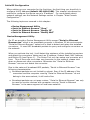
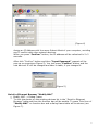
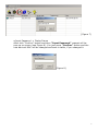
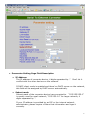
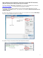
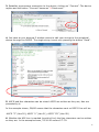
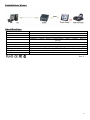
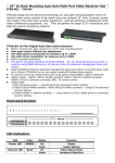
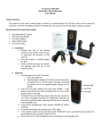
RS232 (Serial) to TCP/IP Converter ITEM NO.: RS005 RS005 RS232 to Ethernet converters (commonly referred to as Terminal Servers or Device Servers) is designed for transmitting serial data across an IP network. Automatically finds devices in the network Configuration over Driver Panels, serial Port,T elnet, WEB Browser, Applications and devices that require an efficient way of communicating with serial RS232 devices over an Ethernet network. RS005 RS232 (Serial) to Ethernet (TCP/IP) Converter Features: Three operation mode :TCP Server, TCP Client, UDP Mode Data Baud rate: 300 ~ 230400 bps Support full duplex transmission Auto detection network 10/100 Mbps Support auto MDI / MDIX LED Indication POWER (Green) Power ON / OFF RJ45 (Green/Yellow) 10/100Mbps Link Data Transmission Tx/Rx (Yellow) Terminal Connection ON / OFF Data Transmission FLASH SYS (Green) System Operation CPU Operation ON / OFF FLASH ON / OFF FLASH Panel view: Function Button: RESET Restore factory default RJ45 Pin Define: Using Standard EIA/TIA 568B ON (press 5 seconds and release) Initial IP Configuration When setting up your converter for the first time, the first thing you should do is configure the IP address (default 192.168.0.200). This chapter introduces the method to configure the device server’s IP address. For more details about network settings, see the Network Settings section in Chapter “Web Console Configuration”. The following topics are covered in this chapter: □□ Device Management Utility □□ Serial to Ethernet Browser “View” □□ Serial to Ethernet Browser “Modify IP” □□ Serial to Ethernet Browser “Modify MAC” Device Management Utility On PC we provide a Device Management Utility named “Serial to Ethernet Browser.exe” which is an executable program in Windows 32 bit environments. “Serial to Ethernet Browser” setup tool is used to detect and setup the installed converters. It uses UDP broadcast packets to query and configure converters on the network. When you activate the tool, it will detect the existence of the installed converters and depict the converters’ status such as IP address, Subnet Mask, MAC Address, and Device ID (see Figure 1). The Setup Tool only can setup one converter at a time. Thus if there are more than one converter on the network, please shut down or disconnect other converters. Otherwise the “Serial to Ethernet Browser”.exe can not detect the converter. Due to the nature of broadcast UDP packets, “Serial to Ethernet Browser” has following characteristics: □□ Broadcast packets are not limited by subnet. Even if the IP address of the converters and the computer running “Serial to Ethernet Browser” do not belong to the same subnet, it still works fine. □□ Broadcast packets can not pass routers. “Serial to Ethernet Browser” can only be used to monitor devices with computer running “Serial to Ethernet Browser” in the same segment of local area network. (Figure 1) 2 Serial to Ethernet Browser “View” View -> Refresh There are two ways for refreshing the status of existing devices. You may select the item “View” to refresh the status of existing devices on LAN. Other one is to click the icon as red color remark as below. “Serial to Ethernet Browser” will send another query to get updated information.(see Figure 2). Note: Always run the “Refresh” after any data change. (Figure 2) File -> Exit or Alt+F4 Exit from the program (see Figure 3). (Figure 3) Serial to Ethernet Browser “Modify IP” Modify IP -> Dialog Frame To click the device on the existing devices list in the “Serial to Ethernet Browser” table and then the function bar will be enable. To press second icon of “Modify IP” on function bar and a dialog frame table will be shown (see Figure 4). 3 (Figure 4) Assign an IP Address with the same Subnet Mask of your computer, avoiding any IP conflict with other network devices. When you press “Confirm” button, the IP address will be refreshed in 2~3 seconds. After click “Confirm” button and then “Input Password” request will be pop-up on screen(see Figure 5). You just press “Confirm” button and the new device’s IP will be changed and save in table, if you changed it. (Figure 5) Serial to Ethernet Browser “Modify MAC” □□ Modify MAC -> Dialog Frame To click the device on the existing devices list in the “Serial to Ethernet Browser” table and then the function bar will be enable. To press Third icon of “Modify MAC” on function bar and a dialog frame table will be shown (see Figure 7). 4 (Figure 7) □□ Input Password -> Dialog Frame After click “Confirm” button and then “Input Password” request will be pop-up on screen (see Figure 8). You just press “Confirm” button and the new device’s MAC will be changed and save in table, if you changed it. (Figure 8) 5 Web Browser Configuration The following topics are covered in this chapter: Serial ● ● ● ● To Ethernet Converter Setup Login Setting Login Setting Page Field Description Parameter Setting Parameter Setting Page Field Description Login Setting In addition to basic IP address and subnet mask, specific device settings can be set through HTTP protocol with popular browsers, e.g. Internet Explorer, Netscape, etc. Setup of the converters is as easy as surfing on WWW, no special software will be required. Popular Browsers, such as IE, or Netscape, can easily do the setup process. In the browser URL field, set the IP address of device directly, to enter the “Login Setting” page, please follow the steps below. □□ Open your browser. This chapter will use IE as an example. □□ In the browser URL field, type the IP address of the converter directly and press ENTER. (The IP address is what you set using the Device Management Utility as “Serial to Ethernet Browser”.) □□ To press fourth icon of “Web Browser” on function bar and a “Login Setting” Screen will be shown (see Figure 9) to login into the device. Alternatively, if the IP address of the converter is already known, you can connect to the converter directly by providing its IP address in the URL field of browsers. (Figure 9) 6 Login Setting Page Field Description □□ System time elapsed The time elapsed since start of this device in [Day : Hour : Minute : Second] format. This information can be useful in identifying the reliability of system. □□ Firmware version Converter firmware is identified by date code. This information will be required in looking for technical support. □□ Serial number It is a product serial number code in the converter device and has been provided by factory. □□ Ethernet MAC Address Converter is an unique MAC (Media Access Control) address used by Ethernet in 6 digits. □□ Password This field is the administration password for authentication. Factory default is “empty”. However, it is not recommended to leave it empty in field operation. If you could not login, it means you have to key in the password. If you do not know the password you can turn off the power and then use any point tip to push “Reset” button and hold it to turn on the power at the same time for 5 seconds. The password will be reset to the factory default as “empty”. Converter device uses the same password protection mechanism commonly used in Windows NT or UNIX. If there are more than “3 consecutive failures” in password check during login, the login function will be disabled for “15 minutes”. During this 15 minutes period, even if you supply correct password, login will not proceed. This prevents intruders from finding the password by computer generated program. Parameter Setting Page □□ The Parameter Setting Page Type the correct password in the “Password” field and click the “Confirm” button in the “Login Setting” page, then the “Parameter Setting” page will be shown (see Figure 10). Note: If you forget the password or can’t login successfully, please contact the manufacturer directly. 7 (Figure 10) □□ Parameter Setting Page Field Description □□ IP Address The IP address of converter device, 4 digits separated by '.' conflict with the other devices on the network. Don’t let it If DHCP client mode is enabled and there's a DHCP server on the network, this field will be assigned by DHCP server automatically. □□ Subnet mask Subnet mask of the converter device has connected to. “255.255.255.0” is usually used for small network, “255.255.0.0” for larger network, 4 digits separated by '.' If your IP address is provided by an ISP or the internal network administrator, please inquire of them that information and type it correctly. 8 If DHCP client mode is enabled and there's a DHCP server on the network, this field will be assigned by DHCP server automatically. □□ Gateway IP address Gateway or Router IP address. 'Gateway' is a device which connects local network to external network. If you need to communicate with other networks or your device owns a real IP address on the internet, please inquire of them that information and type it correctly. If there's no gateway on the network, just leave it as “0.0.0.0”. If DHCP client mode is enabled and there's a DHCP server on the network, this field will be assigned by DHCP server automatically. □□ Link Modes RS005 support five mode of Ethernet link speed: Auto detect / 100 Full / 100 Half / 10 Full / 10 Half □□ DHCP client DHCP client mode could be enabled/disabled statues. If DHCP is enabled, there should be a DHCP server on the network. If DHCP is disabled, [IP address], [Subnet mask], and Gateway address] should be manually assigned. □□ Auto Reset It is for setting when the device has been disconnected or some reasons, the data did not transmit a while. You can prevent it and restart the device after waiting a while (1~99 hours) as your settings. □□ Device Name You can rename RS005 to any name you prefer for identify, default name is RS232_TCPIP □□ Login Password For security and management issues, you may setup the “Login Password”. This administration password uses to login converter parameter setting pages. It may be empty or up to 15 characters long. □□ Serial I∕O Port 1 (RS-232) This converter device model is provided one serial port as RS-232 interface for connecting the extension serial device. □□ Local Port ∕ Socket Mode ∕ Remote IP & Port This device is provided of 1 Local and 1 Remote IP & Ports. □□ Local Port number A socket port assigned for the serial port. It’s a 16-bit numbers, ranging from 1 to 65535. Because the numbers below 1000 are used for specific purposes (e.g. 80 is for HTTP protocol), we suggest you use the numbers larger than 100. Generally the port number 4660 is used for the serial communication. However you should specify different port number for each serial port. 9 □□ Socket mode TCP Server: TCP protocol, passive open, to be connected from the TCP clients. TCP Client: TCP protocol, active open, connect to the TCP server. UDP Mode: UDP protocol, connectionless □□ Remote IP address The server IP address and socket port would be connected in TCP Server, TCP Client and UDP Client mode for a certain serial port. □□ Remote socket port The server socket port would be connected in TCP Client and UDP Client mode for a certain serial port. □□ Interface of serial I/O RS232:TxD, RxD for data stream, no flow control RS232 (RTS/CTS):TxD, RxD for data stream, RTS/CTS for flow control. □□ Baudrate Baud Rate: 300 ~ 230400 bps □□ Parity, Data bits, Stop bit Parity: None, Even, Odd, Space, Mark. Data Bits: 5, 6, 7, 8. Stop Bit: 1 or 2. □□ Force off-line time It is for setting how long the off-line time of device will be taken when there is no date input. The parameter can be from “0 to 99” and the time unit is “Minute”. □□ Packet Collect Time It is for setting a packet collecting period of the device serial port’s Tx and Rx. The parameter can be from “0 to 999” and the time unit is “mSec”. 10 Controller Updated Press “Update”] Button After you finish the detailed parameter setting. The converter will save all parameters into internal non-volatile memory and then reboot (see Figure 11). It takes about 5 seconds to complete the whole process, and a new login page will be presented. (Figure 11) You can re-login and check if all parameters have been correctly saved. If everything is ok, you can close the browser now. Note : If the domain of the converter is different from that of the computer running the browser, the login page won’t appear unless the converter’s “Gateway Address” has been correctly set. Factory Default Setting If by chance, you forget the setup password, or have incorrect settings making the converter inoperable, there are two ways to reset the setting and the following procedures can be used to reset all settings to factory default: You can turn off the power and then use any point tip to push “Reset” button and hold it to turn on the power at the same time for 5 seconds. The password will be reset to the factory default as “empty”. 11 Run a software able to perform a serial port terminal (RS-232 terminal) , UDP/IP terminal and TCP/IP Client Server terminal. The free software “hercules_3-2-6.exe” that can be downloaded from web site http://bit.ly/1Od8KJ is a very useful and powerful interface. To provide a step-by-step example, see the following pages that show how the “hercules_3-2-6.exe” works. This software is provided by HW Group and is in its integral version. 1. First of all, because you act from PC side you must select the window TCP Client. Then you insert Module IP and Port numbers. 2. make a “Ping” to the device that must responds as shown 12 3. Establish a permanent connection to the device, clicking on “Connect”. The device replies and the button “Connect” becomes “X Disconnect” 4. You have at your disposal 3 window where to edit your strings to the peripheral device through the RS005. The single string is sent only pressing the button “Send”. 5. ASCII and Hex characters can be mixed. ASCII are written as they are, Hex are preceded by $. In the example shown, P0$0D means that the characters sent on RS232 line will be: -ASCII “P” (Hex 50), ASCII “0” (Hex 31), ASCII “CR” (Hex 0D) 6. Whether the HEX box is marked (see third line) the Hex characters can be written as they are. In the example shown, 53 54 0D means S T CR. 13 Installation View: Specification: ITEM NO TCP/IP Ethernet RS232 Interface Baud Rate Speed LED Indication Function button Power Adapter Power Consumption (Max). Temperature Dimensions mm Weight g RS005 RJ45 x 1 DB9 x 1 MALE 300 ~ 230400 bps POWER x 1 (Green),RJ45 x 1 (Green/Yellow),Tx/Rx x 1 (Yellow), SYS x 1 (Green) 1 DC 5V 500mA 220mA @ 10/100Mbps Operation: 0 to 55℃, Storage: -20 TO 85℃, Humidity: up to 95% 67 x 91 x 27 145 Rev. A 14