1
Perimetric Joint Meter Assembly
User Manual
Man115
2.1.1
04/08/2014
Chris Spalton
Andy Small
Chris
Rasmussen
Manual No.
Revision
Date
Originator
Checked
Authorised for
Issue
User Manual
1
Contents
Section 1 :
Introduction ................................................................................................................................. 3
Section 2 :
General Information ................................................................................................................. 4
Section 3 :
Installation Techniques ........................................................................................................... 5
3.01
3.02
3.03
3.04
3.05
3.06
Preliminary Tests ........................................................................................................................... 5
Installing the Gauges.................................................................................................................... 5
Initial Setting - Base Reading Ni. .............................................................................................. 6
Cabling and Terminal Units ......................................................................................................... 7
Cable Jointing with 3M Splice Kit ............................................................................................... 7
Terminal Units ................................................................................................................................ 7
Section 4 :
Data Reduction ........................................................................................................................... 9
Section 5 :
Temperature Correction ........................................................................................................ 10
Section 6 :
Environmental Factors ........................................................................................................... 11
Section 7 :
Troubleshooting ....................................................................................................................... 12
Appendix A.
User Manual
Typical Works Calibration Data Sheet ........................................................................... 13
2
Section 1 : Introduction
This instruction manual describes the techniques required for the installation and reading of the
acoustic (Vibrating Wire) Perimetric Jointmeter.
It is essential that the equipment covered by this manual should be installed and operated by
competent and suitably qualified personnel.
The techniques described are intended to serve as a general guide and will vary to suit
particular site conditions.
User Manual
3
Section 2 : General Information
The Soil Instruments acoustic (Vibrating Wire) Perimetric Joint Meter has been designed
specifically for use on concrete-faced dams to measure movement across the perimetric
joint between the concrete face and plinth, either perpendicular or parallel to the
perimetric joint, in the plane of the concrete face or normal to it. However, the system is
suitable for any application where remote monitoring of the differential movement in
three dimensions of adjacent concrete blocks is necessary.
User Manual
4
Section 3 : Installation Techniques
3.01 Preliminary Tests
Upon receipt of the instrument, the Jointmeter should be immediately checked for proper
operation (including the thermistor, if included). This shall be done after removal of the
PVC protective cap. To avoid twisting the piston rod pressing in plugger must be used to
remove force of the piston from the PVC cap while unscrewing it. Due to the strength of
the main spring this operation is advised to be carried out by two individuals. When the
protective PVC cap is removed the piston rod will be pushed out by the main spring. The
jointmeter is ready for preliminary test as follows.
Connect the gauge leads to the readout unit. The reading (in Period x 10 7 units) shall be
within a band of 3500 to 3800. The reading stability shall be within +/- 1 digit when the
Jointmeter is in stationary, vibration free environment. Pushing in the piston rod by a
few millimetres will change the reading which shall return to its original value when the
piston rod returns under main spring force.
A swivel ball joint between piston rod and Transducer spring protects the wire from
damage due to rotation of the piston rod. As the ball joint is not entirely friction free
rotation of the piston rod may cause the wire to twist slightly before the ball rotates in
the socket. This twist in the wire will result in a change in reading. In severe cases the
wire which has torsional stresses added to pure tensile stresses will give a distorted
signal.
Check the transducer by pushing the piston rod into the Jointmeter body in small steps.
At each step a steady reading and clear ring of audio signal indicates a torsion free wire.
Push the rod in completely i.e. full range. If the audio signal becomes dull with erratic
reading during this check the wire is under torsion stress. These can be cleared by
assisting the ball to rotate in its socket by gently tapping the instrument with a soft
object. Repeat the check again and ensure that the transducer gives clear steady signal
throughout the range before it is installed.
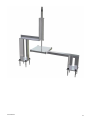
3.02 Installing the Gauges
The relative position of the jointmeter mounting bracket and the reaction (target) plate
mounting bracket will determine the limits of movement of each instrument and its initial
setting. Once the direction of movement and initial setting has been decided for each
installation point fixing of mounting and support brackets for jointmeter and the reaction
(target) plate frames can be proceeded with.
Accurately mark out on the concrete face at the required construction joint the centres
and axes of movement (parallel, perpendicular, normal) ensuring that all are precisely
parallel, etc to the joint, making due allowances for the expected range of movement,
type and dimensions of the gauges, joint width, reaction (target) plate dimensions etc.
Drill suitable holes for the jointmeter mounting and support brackets. Bolt these firmly
to the concrete face with the expanding masonry bolts supplied, bedding into epoxy resin
as necessary for intimate contact, ensuring perpendicularity of the jointmeter to the
reaction plate. Follow a similar procedure to mount the respective reaction (target) plate
bracket.
When no shrink grout or similar epoxy resin used is fully cured the mounting brackets for
jointmeter and reaction (target) plates are rigidly fixed to concrete. Smooth polished
User Manual
5
stainless steel reaction plate is now assembled to the bracket with four screws.
Perimetric jointmeter can now be mounted on the fixed brackets. In order to check the
initial setting obtains a pre-installation base reading No. by connecting a readout to the
jointmeter with piston rod fully out of the body. Pass the jointmeter through the support
bracket U bolt and the mounting bracket piston rod facing the reaction (target) plate.
Push the piston rod against the reaction (target) plate and screw the nut on nose
mounting thread of the jointmeter. Fully tighten the nut. The jointmeter piston rod
semi-spherical head is in firm contact with polished stainless steel reaction (target)
plate.
3.03 Initial Setting - Base Reading Ni.
Initial setting of the Triaxial Jointmeter is achieved by assembling it to pre-fixed
mounting brackets facing the reaction plate. When fully assembled the reading will
correspond to the position of the piston at a point on its full scale deflection. This can be
calculated as follows:
Obtain the gauge constant of the Jointmeter from its Calibration Certificate.
Obtain the pre-installation zero reading.
Note the current reading with a Vibrating Wire readout in Period x 107 units.
Substitute the values in the formula given in the Calibration Certificate.
Example
Gauge Constant K
: 80.1028
Pre-installation Test No
: 4166
Initial Setting Ni
: 5028
Position of piston
rod at initial setting = 80.1028
10 7
10 7
4146 2 5028
= 14.91mm
The Jointmeter is set at 14.91mm of its full scale span.
check the initial setting of each Jointmeter.
This method can be used to
Having finally locked it in position a note of initial zero/reference reading Ni must be
recorded on the installation sheet of each Jointmeter. All subsequent readings from the
Jointmeter will represent linear movement of the structure from the time of initial
setting.
Good installation practice requires making a note of date, time, atmospheric conditions,
temperature, pressure and detail of readout equipment used.
Having completed the installation and recorded initial reading, cables can be routed
through the ducts and tubes to a junction box according to procedure described below.
User Manual
6
3.04 Cabling and Terminal Units
It is possible to use a portable readout or data logger to take readings from Jointmeters
individually at the installation point. But it is often more convenient to extend the
transducer cables to a central location. Because vibrating wire transducers have an
output signal in frequency rather than current or voltage, slight variations in cable
resistance have no detrimental effect on gauge readings. Consequently, splicing has no
effect on instrument performance allowing cables to be spliced and routed to junction
boxes and then connected to multi conductor cables for transmission to a central location
3.05 Cable Jointing with 3M Splice Kit
Thoroughly scrape all wax and dirt from each cable end for approx. 150mm. Prepare the
cable ends as shown. Stagger the individual conductor connections.
Use crimped connectors to join the conductors. Ensure Electrical continuity of outer
armour/screen is re-established across joint. Use the electrical insulation tape to wrap
the connectors. Stretch the tape to half its original width and apply one layer half lapped
over connector area only. Do not wrap the tape beyond the pencilled area.
Trim the ends of the mould with a sharp knife to suit the diameter of the cable. Hold the
mould halves in place centred over the splice. Snap both halves together and fit the
pouring spouts in the holes. Ensure that both seams are completely snapped together.
Tape the ends of the mould body to form a seal.
Mix the resin thoroughly and maintaining the mould in a level position, spouts
uppermost, pour the resin through one spout until both spouts are completely filled.
When the resin has solidified and cooled remove the spouts.
NOTE:
In cold weather (below 15 degrees C) the resin becomes very viscous.
It is therefore advisable to keep the resin in a warm place prior to
mixing. Mix the compound until its temperature starts to rise, this
decreases the viscosity.
3.06 Terminal Units
The cables are normally terminated in multi-channel terminal units. The cables enter
through waterproof glands. The terminal units have a hinged cover secured by two
screws.
Unscrew and open the hinged cover. Unscrew the four fixing screws holding the terminal
panel and carefully remove it without straining the connecting leads.
Prepare the cables by stripping and cutting back 20 mm approx. of the outer insulation
and armour/screen. Remove the insulation and strip back 5 mm of the conductor
insulation.
Slacken the entry glands and insert the cables. Make connections to the contact blocks.
The earth leads from transducers are not normally connected at the terminal units but
leave sufficient lengths available to allow this to be done retrospectively should site
User Manual
7
conditions require it. Then tighten the glands to grip the cables.
Replace the terminal panel and secure. Connect the readout unit to each instrument in
turn to check connections.
User Manual
8
Section 4 : Data Reduction
Each Soil Instruments Limited Vibrating Wire Jointmeter is calibrated and comes with a
standard Calibration Certificate giving the Gauge constant and temperature at the time
of calibration. A sample Calibration Certificate is included in this manual as Appendix 'A'.
Calibration is carried out by pushing in the piston rod to full range while it is coupled to a
micrometer. Slip gauges can also be used for this purpose by wedging them between
the piston rod and the reaction plate. Readings are taken at full range displacement, a
number of intermediate points and at zero extension.
The gauge factor is then
calculated using the expression given in the Calibration Certificate specimen.
Following the installation instructions the initial reference reading Ni is noted which
indicates zero movement. Subsequent data obtained from the Jointmeter can be
reduced to linear movement in millimetres by using the gauge constant in the equation
given in the Calibration Certificate. An example of data reduction is as follows;
Gauge Constant:
Reference Reading
K
Ni:
mm: 120.4254
6320
(Zero measurement)
Example 1: Subsequent Reading N1: 4820
Equivalent Linear Movement: P = K x
10 7 10 7
2 2
N1
N1
(Joint opening)
= - 21.685mm
Example 2: Subsequent Reading N2: 6740
Equivalent Linear Movement: 120.4254
10 7
10 7
{6320}2 {6740}2
(Joint opening)
P = 3.6404mm
Note: A negative sign represents opening up of a joint and vice versa.
User Manual
9
Section 5 : Temperature Correction
The transducer working elements are made primarily of steel and stainless steel and are
affected by changing temperature to a certain predictable degree. In case of large
temperature changes application of temperature correction will improve the accuracy of
the measurements. The approximate temperature effect on the gauge is 0.0125mm per
degree Celsius. Hence for a temperature increase of 10°C a transducer will indicate
(0.0125 x 10) 0.125mm reduction in linear measurement. Correction is applied by
adding 0.125mm to the result indicated by the transducer reading. A fall in temperature
will result in a positive change in linear measurement which can be corrected
accordingly. Physical dimensional changes due to temperature in the transducer and the
structure on which it is mounted are of the order of 10-6m/m/°C and can be neglected.
User Manual
10
Section 6 : Environmental Factors
Since the purpose of the transducer installation is to monitor site conditions, factors
which may affect these conditions should always be observed and recorded. Seemingly
minor effects may have a real influence on the behaviour of the structure being
monitored and may give an early indication of potential problems. Such factors include
but are not limited to: blasting, rainfall, tidal levels, excavation and fill levels and
sequences, site traffic, temperature and barometric changes, changes in personnel
reading the instruments, nearby construction activities, seasonal changes, etc.
User Manual
11
Section 7 : Troubleshooting
Maintenance and troubleshooting of vibrating wire Jointmeters is confined to periodic
checks of cable connections and maintenance of terminals. The transducers themselves
are sealed and cannot be opened for inspection.
If a unit fails to read, the following steps should be taken:
1)
Check the coil resistance. Nominal coil resistance is 130 ± 5O, plus cable resistance
(for 22 gauge copper resistance is approximately 1O/15m). Check resistance across
positive/negative and earth conductor.
2)
If resistance is high or infinite, a severed cable must be suspected.
3)
If the resistance is low or near zero, a short must be suspected.
4)
If the resistance of coil is 130 ± 5O and coil and earth is of a finite value (not
infinite), then a leakage to earth is suspected due to damaged cable.
5)
If resistances are within the nominal range and no reading is obtained the
transducer is suspect and Soil Instruments should be consulted.
6)
If all resistances are within nominal range and readings cannot be obtained on any
transducer, the readout unit is suspect and Soil Instruments should be consulted.
7)
If cuts and shorts are located, the cable can be spliced in accordance with
recommended procedures.
Bell Lane, Uckfield, East Sussex
t: +44 (0) 1825 765044
e: [email protected]
TN22 1QL United Kingdom
f: +44 (0) 1825 744398
w: www.itmsoil.com
Soil Instruments Ltd. Registered in England. Number: 07960087. Registered Office: 5th Floor, 24 Old Bond Street, London, W1S 4AW
User Manual
12
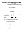
Appendix A.
Typical Works Calibration Data Sheet
Soil Instruments
VIBRATING WIRE INSTRUMENT CALIBRATION CERTIFICATE
Instrument Type : VW JOINTMETER
Range :
0 to 50 mm
Serial No
: 50/208 /J
Customer/Contract :
Soil Instruments
-------------------------------------------------------------------------WORKS CALIBRATION DATA
Date of Calibration : 05/06/89
o
Ambient Temperature : 21 C
Gauge Constant [mm].(K) = -121.1036
Calibrated By:
Certified By:
Barometric Pressure : 1028 mbars
Works File No.
: XXX
-------------------------------------------------------------------------FIELD READINGS
Readout displaying
period x 10
Readout displaying
7
frequency2 x 10-3
Routine Readings
Indicated Change
P = K (107 - 107)
(Ni2
from reference setting:
Gauge Constant
K=
R
2
( No
R
N12)
K=
( 107 - 107 )
(See Note 1)
Where
P = K(Ni - N1) x 10-4
R
x 104
(No - Nr)
2
Nr )
= Calibrated instrument range in millimetres
No,Nr= Initial and full scale calibration readings
Ni
= Reference reading at initial setting
P
= Indicated change in millimetres
K
= Gauge Constant
N1
NOTE 1
= Routine Reading displayed by readout
The works gauge constant may be checked by user after
recalibration by using the above formulae.
NOTE 2
For data on temperature and barometric pressure effects,
refer to the users manual.
NOTE 3
Zero reading 'No' must be established by user on site
on installation.
NOTE:
User Manual
BAROMETRIC PRESSURE DOES NOT AFFECT VW JOINTMETERS
(TRIAXIAL)
13
User Manual
14
User Manual
15