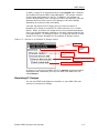
1
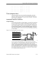
Synario ABEL-HDL Design Considerations
Pin-to-pin vs. Detailed Descriptions
for Registered Designs
You can use ABEL-HDL assignment operators when you write highlevel equations. The = operator specifies a combinational assignment,
where the design is written with only the circuit's inputs and outputs in
mind. The := assignment operator specifies a registered assignment,
where you must consider the internal circuit elements (such as output
inverters, presets and resets) related to the memory elements
(typically flip-flops). The semantics of these two assignment operators
are discussed below.
Using := for Pin-to-pin Descriptions
The := implies that a memory element is associated with the output
defined by the equation. For example, the equation;
Q1 := !Q1 # Preset;
implies that Q1 will hold its current value until the memory element
associated with that signal is clocked (or unlatched, depending on the
register type). This equation is a pin-to-pin description of the output
signal Q1. The equation describes the signal's behavior in terms of
desired output pin values for various input conditions. Pin-to-pin
descriptions are useful when describing a circuit that is completely
architecture-independent.
Language elements that are useful for pin-to-pin descriptions are the
":=" assignment operator, and the .CLK, .OE, .FB, .CLR, .ACLR,
.SET, .ASET and .COM dot extensions described in the ABEL-HDL
Reference Manual. These dot extensions help resolve circuit
ambiguities when describing architecture-independent circuits.
Resolving Ambiguities
In the equation above (Q1 := !Q1 # Preset;), there is an ambiguous
feedback condition. The signal Q1 appears on the right side of the
equation, but there is no indication of whether that fed-back signal
should originate at the register, come directly from the combinational
logic that forms the input to the register, or come from the I/O pin
associated with Q1. There is also no indication of what type of register
should be used (although register synthesis algorithms could,
theoretically, map this equation into virtually any register type). The
equation could be more completely specified in the following manner:
Q1.CLK = Clock;
"Register clocked from input
Q1 := !Q1.FB # Preset; "Reg. feedback normalized to pin value
This set of equations describes the circuit completely and specifies
enough information that the circuit will operate identically in virtually
any device in which you can fit it. The feedback path is specified to be
from the register itself, and the .CLK equation specifies that the
memory element is clocked, rather than latched.
Synario ABEL Designer User Manual
5-7