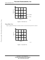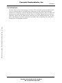
1
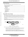
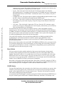
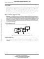
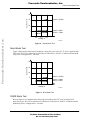
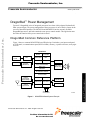
Freescale Semiconductor, Inc.
Freescale Semiconductor
Order by AN1767/D
(Motorola Order Number)
Rev. 0, 09/98
DragonBall™ Power Management
DragonBall Common Reference Platform
Figure 1 shows a common MC68EZ328-based PDA design. It includes a pen-input touch panel,
an LCD panel, a communications port (RS232 or IrDA), memory, a speaker or buzzer, and a pager
receiver.
MC68EZ328
Interrupt
Timer
Controller
Module
Touch
Panel
RF/IF
A/D
FLEX/POCSAG
Decoder
(MC68177)
ICE Module
RTC
SPI Master
LCDC
Pulse with Modulator
Static Core
68EC000
LCD Panel
Audio Amp
(MC34119)
8/16-bit Bus Interface
Power Control
RS232
Transceiver
(MC145583)
Infared
Transceiver
I/O Ports
DRAMC
UART IrDA
Chip Select
Bootstrap
PLL
RAM/DRAM
ROM/FLASH
32.768 kHz
or 38.4 kHz
Figure 1. MC68EZ328-Based System Example
© Freescale Semiconductor, Inc., 2004. All rights reserved.
For More Information On This Product,
Go to: www.freescale.com
AA1912
DragonBall™ Power Management
Freescale Semiconductor, Inc...
Freescale’s DragonBall series of integrated processors have been widely adopted for hand-held
PDA system designs. The power management of these processors is one of the key factors in the
success of hand-held products. The MC68328 and MC68EZ328 are the currently available
DragonBall processors, and both contain the same power control module. This application note
describes the function of the power control unit in detail.
Freescale Semiconductor, Inc.
DragonBall Power Modes
Content Organization
Freescale Semiconductor, Inc...
Please refer to the following list for a description of this application note’s contents.
“DragonBall Common Reference Platform” .......................................................................................... 1
“Content Organization”.................................................................................................................... 2
“DragonBall Power Modes”................................................................................................................... 2
“Burst Mode” ................................................................................................................................... 3
“DOZE Mode” ................................................................................................................................. 3
“Sleep Mode” ................................................................................................................................... 4
“Power Consumption Test” .................................................................................................................... 4
“Test Hardware Set-Up” .................................................................................................................. 4
“Normal Mode Test”........................................................................................................................ 4
“Burst Mode Test” ........................................................................................................................... 5
“DOZE Mode Test” ......................................................................................................................... 5
“Sleep Mode Test” ........................................................................................................................... 6
“Conclusions”......................................................................................................................................... 7
DragonBall Power Modes
Based on application needs, the DragonBall can operate in any of four modes: normal mode, burst
mode, DOZE mode, and sleep mode. Properly applied, power-saving techniques can result in minimal
power consumption for the entire system and can thus extend battery life. The current consumption
values specified in the DragonBall user’s manual represent the maximum normal mode value as well
as a sleep mode value. In real-world applications, DOZE mode is used most of the time the system is
up and running.
The DragonBall processors acheive power savings by minimizing bus activity while optimizing
system and CPU clock frequencies. Figure 2 shows the clock tree model of the internal phase lock
loop (PLL) and power management circuit.
d
External
Clock Input
Frequency
Select
VCO
Sysclk
Divider
Pixclk
Divider
Sysclk
CPU Clock
Burst Control
CPU Clock
Peripheral Modules
Pixel Clock
AA1913
Figure 2. Clock Tree Model of Internal PLL
Please refer to the following list for a description of the elements of Figure 2.
•
•
External clock input—Both 32.768KHz and 38.4KHz crystals can be used as the PLL input
frequency. A frequency of 32.768KHz is recommended. Throughout this application note,
32.768KHz, or simply 32KHz, will be assumed as the input reference.
Voltage-controlled oscillator (VCO)—This is the output frequency of the PLL’s VCO. Its
default output frequency, for a 32KHz input, is 16.58MHz. The VCO frequency can be
changed from approximately 9MHz to 23 MHz through programming of the P and Q values of
DragonBall™ Power Management
For More Information On This Product,
Go to: www.freescale.com
Freescale Semiconductor, Inc.
DragonBall Power Modes
•
•
•
Freescale Semiconductor, Inc...
•
frequency select register. Note that the VCO frequency can be maintained at its default value
while achieving power saving requirements for the system.
Sysclk—This clock signal is derived from the VCO through a divider. By default the
MC68328 divides by 1, generating a Sysclk frequency of 16.58MHz after reset. By default the
MC68EZ328 divides by 2 (EZ328 has a 1-bit Prescaler which is set by default), so Sysclk is
Normal Mode
8.29MHz after reset. The Sysclk output is applied to all DragonBall peripheral modules except
the RTC, which is clocked directly from the external 32KHz crystal.
Pixel clock—This clock is used for the LCD pixel generation. It is separated from Sysclk so
that changing the system-clock frequency for power saving will not affect the LCD screen
refresh rate.
CPU clock—This clock signal is input to the CPU core. Since the CPU consumes a major
portion of overall power, changing the CPU clock frequency and burst duty cycle will directly
affect the DragonBall power consumption.
In normal mode the system is running at its highest frequency, and the DragonBall consumes
maximum power. The maximum system clock frequency for both the MC68328 and MC68EZ328 is
16.58Mhz. The 68K core performance at this frequency is 2.7 million instructions per second (MIPS).
If the system requires a peak performance lower than 2.7 MIPS, a lower system clock frequency can
be used by programming the system-clock divider accordingly.
The system-clock frequency can be rescaled from 16MHz down to 1MHz for the MC68328 by
programming the system-clock divider bits in the PLL control register ($FFF200). For the
MC68EZ328, the system-clock frequency can be scaled down to 512KHz by programming the
prescaler and divider bits.
Because most of the modules, such as the UART, SPI, TIMER, and PWM, use the system clock for bit
rate generation, changing the system-clock frequency will also change the system timing. Therefore,
once a system-clock frequency is selected, it should not be changed during system operation. Burst
and DOZE modes are then used for power saving.
Burst Mode
If the user wants to keep the modules enabled at a high system-clock frequency during normal
operation without requiring maximum CPU performance, burst CPU clock-control mode can be
enabled. The period of a burst is 1 ms, and the duty-cycle of a burst is controlled by the value of the
WIDTH bits in the power control register. The user can choose from 1/31 to 31/31 of 1 ms of CPU
active time for every 1 ms burst period. A WIDTH value of zero will place the CPU in DOZE mode.
Smaller values of WIDTH will reduce system power consumption.
Burst mode is often used in data-polling applications. Burst mode is entered by setting the PC EN bit
and program the WIDTH bits of the power control register. Burst mode is disabled automatically when
there is an interrupt event. Clearing the PC EN bit will also disable burst control.
DOZE Mode
For many PDA applications, the system takes only a little time to process tasks the user requests, after
which the system waits again for user commands, such as a touch screen input. During the waiting
period, some peripherals like the LCD screen must be active. Therefore, the developer can stop the
CPU in these waiting periods using DOZE mode.
As mentioned before, DOZE mode is entered by setting the PC EN bit and clearing the WIDTH bits of
the power control register. DOZE mode is disabled automatically when there is an interrupt event.
For More Information On This Product,
Go to: www.freescale.com
Freescale Semiconductor, Inc.
Power Consumption Test
Sleep Mode
In sleep mode the CPU and all peripherals but the RTC are in an inactive state. Sleep mode is entered
by disabling PLL, thus stopping the system clock. Only the external 32KHz clock still inputs to the
RTC module. Because 32KHz is a low-frequency signal, the RTC consumes less than 1 uA.
When disabling the PLL to enter sleep mode, please follow the PLL shut-down sequence specified in
the DragonBall user’s manual. Sleep mode is disabled automatically when there is an interrupt event.
Note that upon wake-up it takes 1 ms for the PLL to stabilize and provide a system clock
Freescale Semiconductor, Inc...
Power Consumption Test
Both the MC68328 and MC68EZ328 user’s manuals state that the maximum current consumption at
3.3V is 20 mA for normal mode and 20uA for sleep mode. The user should remember that “system up”
does not always mean “full running.” Burst or DOZE mode can be used. In burst/DOZE mode, current
consumption is substantially less than 20mA. Power tests with the MC68328 and MC68EZ328 show
that they both consume similar amounts of current in the same configuration. Refer to the following
sections for benchmark data.
Test Hardware Set-Up
Figure 3 shows the hardware set-up for this power measurement.
A
V
68EZ328
VCC
Power
Supply
8-bit
ROM
AA1914
Figure 3. Hardware Configuration for Power Consumption Test
Normal Mode Test
Figure 4 graphs the following test condition: the CPU is continuously running; the LCD controller is
enabled and initialized to 240x160 b/w; the RTC is enabled; and the ROM chip-select is configured for
1 wait state.
DragonBall™ Power Management
For More Information On This Product,
Go to: www.freescale.com
Freescale Semiconductor, Inc.
Power Consumption Test
Current, mA
20
15
Sysclk = 16 MHz
10
Sysclk = 4 MHz
Sysclk = 1 MHz
3.0
3.3
3.6
Voltage, V
AA1915
Figure 4. Normal Mode Test
Burst Mode Test
Figure 5 diagrams the following test condition: a burst-duty cycle value of 1/31 clock is applied to the
CPU clock; the LCD is enabled and is initialized to 240x160 b/w; the RTC is enabled; and the ROM
chip select is configured for 1 wait state.
20
Current, mA
Freescale Semiconductor, Inc...
5
15
10
Sysclk = 16 MHz
5
Sysclk = 4 MHz
Sysclk = 1 MHz
3.0
3.3
3.6
Voltage, V
AA1916
Figure 5. Burst Mode Test
DOZE Mode Test
Refer to Figure 6 for a diagram of the following test condition: the CPU clock is stopped (0/31
burst-duty cycle); the LCD is enabled and is initialized to 240x160 b/w; the RTC is enabled; and the
ROM chip select is configured for 1 wait state.
For More Information On This Product,
Go to: www.freescale.com
Freescale Semiconductor, Inc.
Power Consumption Test
Current, mA
20
15
10
Sysclk = 16 MHz
5
3.0
3.3
3.6
Voltage, V
AA1917
Figure 6. DOZE Mode Test
Sleep Mode Test
Figure 7 graphs the following test condition: the PLL is turned off and only the RTC is enabled.
20
Current, µA
Freescale Semiconductor, Inc...
Sysclk = 1 MHz
15
10
5
3.0
3.3
3.6
Voltage, V
AA1918
Figure 7. Sleep Mode Test
DragonBall™ Power Management
For More Information On This Product,
Go to: www.freescale.com
Freescale Semiconductor, Inc.
Conclusions
Conclusions
Freescale Semiconductor, Inc...
The most effective power-control strategy is to run the CPU at its highest system speed until no CPU
cycles are needed and then to enter DOZE mode. Other power-saving system-design techniques
include the use of interrupts, instead of data polling, and configuring unused I/O pins to be inputs. It is
important not to enable internal pull-up resisters unless it is necessary. (Internal pull-up resisters are
100K ohms.) Finally, the user should disable external devices before entering sleep mode. Use of the
modes and techniques listed in this application note should result in an optimally low system power
dissipation for the DragonBall processors.
For More Information On This Product,
Go to: www.freescale.com
Freescale Semiconductor, Inc.
How to Reach Us:
Home Page:
www.freescale.com
E-mail:
[email protected]
Freescale Semiconductor, Inc...
USA/Europe or Locations Not Listed:
Freescale Semiconductor
Technical Information Center, CH370
1300 N. Alma School Road
Chandler, Arizona 85224
+1-800-521-6274 or +1-480-768-2130
[email protected]
Europe, Middle East, and Africa:
Freescale Halbleiter Deutschland GmbH
Technical Information Center
Schatzbogen 7
81829 Muenchen, Germany
+44 1296 380 456 (English)
+46 8 52200080 (English)
+49 89 92103 559 (German)
+33 1 69 35 48 48 (French)
[email protected]
Japan:
Freescale Semiconductor Japan Ltd.
Headquarters
ARCO Tower 15F
1-8-1, Shimo-Meguro, Meguro-ku,
Tokyo 153-0064
Japan
0120 191014 or +81 3 5437 9125
[email protected]
Asia/Pacific:
Freescale Semiconductor Hong Kong Ltd.
Technical Information Center
2 Dai King Street
Tai Po Industrial Estate
Tai Po, N.T., Hong Kong
+800 2666 8080
[email protected]
How to Reach Us:
Home Page:
www.freescale.com
E-mail:
[email protected]
USA/Europe or Locations Not Listed:
Freescale Semiconductor
Technical Information Center, CH370
1300 N. Alma School Road
Chandler, Arizona 85224
+1-800-521-6274 or +1-480-768-2130
[email protected]
Europe, Middle East, and Africa:
Freescale Halbleiter Deutschland GmbH
Technical Information Center
Schatzbogen 7
81829 Muenchen, Germany
+44 1296 380 456 (English)
+46 8 52200080 (English)
+49 89 92103 559 (German)
+33 1 69 35 48 48 (French)
[email protected]
Japan:
Freescale Semiconductor Japan Ltd.
Headquarters
ARCO Tower 15F
1-8-1, Shimo-Meguro, Meguro-ku,
Tokyo 153-0064
Japan
0120 191014 or +81 3 5437 9125
[email protected]
Asia/Pacific:
Freescale Semiconductor Hong Kong Ltd.
Technical Information Center
2 Dai King Street
Tai Po Industrial Estate
Tai Po, N.T., Hong Kong
+800 2666 8080
[email protected]
For Literature Requests Only:
Freescale Semiconductor Literature Distribution Center
P.O. Box 5405
Denver, Colorado 80217
1-800-441-2447 or 303-675-2140
Fax: 303-675-2150
[email protected]
For Literature Requests Only:
Freescale Semiconductor Literature Distribution Center
P.O. Box 5405
Denver, Colorado 80217
1-800-441-2447 or 303-675-2140
Fax: 303-675-2150
[email protected]
Information in this document is provided solely to enable system and software
implementers to use Freescale Semiconductor products. There are no express or
implied copyright licenses granted hereunder to design or fabricate any integrated
circuits or integrated circuits based on the information in this document.
Freescale Semiconductor reserves the right to make changes without further notice to
any products herein. Freescale Semiconductor makes no warranty, representation or
guarantee regarding the suitability of its products for any particular purpose, nor does
Freescale Semiconductor assume any liability arising out of the application or use of
any product or circuit, and specifically disclaims any and all liability, including without
limitation consequential or incidental damages. “Typical” parameters which may be
provided in Freescale Semiconductor data sheets and/or specifications can and do
vary in different applications and actual performance may vary over time. All operating
parameters, including “Typicals” must be validated for each customer application by
customer’s technical experts. Freescale Semiconductor does not convey any license
under its patent rights nor the rights of others. Freescale Semiconductor products are
not designed, intended, or authorized for use as components in systems intended for
surgical implant into the body, or other applications intended to support or sustain life,
or for any other application in which the failure of the Freescale Semiconductor product
could create a situation where personal injury or death may occur. Should Buyer
purchase or use Freescale Semiconductor products for any such unintended or
unauthorized application, Buyer shall indemnify and hold Freescale Semiconductor
and its officers, employees, subsidiaries, affiliates, and distributors harmless against all
claims, costs, damages, and expenses, and reasonable attorney fees arising out of,
directly or indirectly, any claim of personal injury or death associated with such
unintended or unauthorized use, even if such claim alleges that Freescale
Semiconductor was negligent regarding the design or manufacture of the part.
For More Information On This Product,
Go to: www.freescale.com