1
INVERTER
INVERTER
Plug-in option
INVERTER
FR-A7NCE
INSTRUCTION MANUAL
FR-A7NCE
Network
communication function
PRE-OPERATION INSTRUCTIONS
1
INSTALLATION
2
WIRING
3
INVERTER SETTING
4
FUNCTION OVERVIEW
5
I/O SIGNAL LIST
6
DETAILS OF I/O SIGNALS
7
PROGRAMMING EXAMPLES
8
HEAD OFFICE: TOKYO BUILDING 2-7-3, MARUNOUCHI, CHIYODA-KU, TOKYO 100-8310, JAPAN
Printed in Japan
Specifications subject to change without notice.
INSTRUCTION MANUAL
IB(NA)-0600453ENG-A(1107) MEE
A
Thank you for choosing this Mitsubishi Inverter plug-in option.
This Instruction Manual gives handling information and
precautions for use of this equipment. Incorrect handling might
cause an unexpected fault. Before using the equipment, please
read this manual carefully to use the equipment to its optimum.
Please forward this manual to the end user.
This section is specifically about
safety matters
Do not attempt to install, operate, maintain or inspect this
product until you have read through this Instruction Manual and
appended documents carefully and can use the equipment
correctly. Do not use this product until you have a full
knowledge of the equipment, safety information and
instructions.
In this Instruction Manual, the safety instruction levels are
classified into "WARNING" and "CAUTION".
WARNING
CAUTION
Incorrect
handling
may
cause
hazardous conditions, resulting in
death or severe injury.
Incorrect
handling
may
cause
hazardous conditions, resulting in
medium or slight injury, or may cause
only material damage.
CAUTION level may even lead to a serious
The
consequence according to conditions. Both instruction levels
must be followed because these are important to personal
safety.
SAFETY INSTRUCTIONS
1. Electric Shock Prevention
WARNING
• While power is ON or when the inverter is running, do not
open the front cover. You may get an electric shock.
• Do not run the inverter with the front cover or wiring cover
removed. Otherwise, you may access the exposed highvoltage terminals and charging part and get an electric shock.
• Even if power is OFF, do not remove the front cover except for
wiring or periodic inspection. You may accidentally touch the
charged inverter circuits and get an electric shock.
• Before wiring or inspection, power must be switched OFF. To
confirm that, LED indication of the operation panel must be
checked. (It must be OFF.) Any person who is involved in
wiring or inspection shall wait for at least 10 minutes after the
power supply has been switched OFF and check that there
are no residual voltage using a tester or the like. The
capacitor is charged with high voltage for some time after
power OFF, and it is dangerous.
• Any person who is involved in wiring or inspection of this
equipment shall be fully competent to do the work.
• The plug-in option must be installed before wiring. Otherwise,
you may get an electric shock or be injured.
• Do not touch the plug-in option or handle the cables with wet
hands. Otherwise you may get an electric shock.
• Do not subject the cables to scratches, excessive stress,
heavy loads or pinching. Otherwise you may get an electric
shock.
A-1
2. Injury Prevention
3) Usage
WARNING
CAUTION
• The voltage applied to each terminal must be the ones
specified in the Instruction Manual. Otherwise burst, damage,
etc. may occur.
• The cables must be connected to the correct terminals.
Otherwise burst, damage, etc. may occur.
• Polarity must be correct. Otherwise burst, damage, etc. may
occur.
• While power is ON or for some time after power-OFF, do not
touch the inverter as they will be extremely hot. Doing so can
cause burns.
3. Additional Instructions
Also the following points must be noted to prevent an accidental
failure, injury, electric shock, etc.
1) Transportation and mounting
• Do not modify the equipment.
• Do not perform parts removal which is not instructed in this
manual. Doing so may lead to fault or damage of the inverter.
CAUTION
• When parameter clear or all parameter clear is performed, the
required parameters must be set again before starting operations
because all parameters return to the initial value.
• For prevention of damage due to static electricity, nearby
metal must be touched before touching this product to
eliminate static electricity from your body.
4) Maintenance, inspection and parts replacement
CAUTION
CAUTION
• Do not install or operate the plug-in option if it is damaged or
has parts missing.
• Do not stand or rest heavy objects on the product.
• The mounting orientation must be correct.
• Foreign conductive objects must be prevented from entering
the inverter. That includes screws and metal fragments or
other flammable substances such as oil.
2) Trial run
CAUTION
• Before starting operation, each parameter must be confirmed
and adjusted. A failure to do so may cause some machines to
make unexpected motions.
A-2
• Do not test the equipment with a megger (measure insulation
resistance).
5) Disposal
CAUTION
• This inverter plug-in option must be treated as industrial
waste.
6) General instruction
Many of the diagrams and drawings in this Instruction Manual
show the inverter without a cover or partially open for
explanation. Never operate the inverter in this manner. The
cover must be reinstalled and the instructions in the inverter
manual must be followed when operating the inverter.
⎯ CONTENTS ⎯
1
PRE-OPERATION INSTRUCTIONS
1.1
1.2
Inverter model ....................................................................................................................................1
Unpacking and product confirmation ..............................................................................................2
1.2.1
1.3
1.4
2
Product confirmation....................................................................................................................................... 3
Parts ....................................................................................................................................................4
CC-Link IE Field Network communication specifications..............................................................6
INSTALLATION
2.1
2.2
2.3
3
4.1
Connection cable.......................................................................................................................................... 14
Hubs ............................................................................................................................................................. 15
Wiring................................................................................................................................................16
3.4.1
3.4.2
4
11
System configuration example.......................................................................................................11
Network configuration.....................................................................................................................12
Network components ......................................................................................................................14
3.3.1
3.3.2
3.4
7
Pre-installation instructions .............................................................................................................7
Installation of the communication option LED display cover .......................................................8
Installation procedure .......................................................................................................................9
WIRING
3.1
3.2
3.3
1
Ethernet cable connection ............................................................................................................................ 16
Precautions................................................................................................................................................... 19
INVERTER SETTING
22
Parameter list ...................................................................................................................................22
I
4.2
Operation mode setting...................................................................................................................23
4.2.1
4.3
4.3.1
4.3.2
4.4
4.5
Network number setting (Pr.434).................................................................................................................. 33
Station number setting (Pr. 435)................................................................................................................... 33
Frequency command with sign (Pr.541)....................................................................................................... 34
FUNCTION OVERVIEW
5.1
5.2
5.3
6
Data flow and link device assignment .......................................................................................................... 37
I/O SIGNAL LIST
6.1
6.2
7
45
Details of remote input and output signals ...................................................................................45
7.1.1
7.1.2
7.2
39
Remote I/O (64 points fixed) ...........................................................................................................39
Remote register (128 words fixed) .................................................................................................41
DETAILS OF I/O SIGNALS
7.1
35
Output from the inverter through the network..............................................................................35
Input to the inverter through the network .....................................................................................36
Cyclic transmission .........................................................................................................................37
5.3.1
Output signals (master module to inverter (FR-A7NCE)) ............................................................................. 45
Input signals (inverter (FR-A7NCE) to master module)................................................................................ 47
Details of remote register................................................................................................................51
7.2.1
7.2.2
II
Operation selection at communication error occurrence (Pr. 500 to Pr. 502) .............................................. 26
Fault and measures...................................................................................................................................... 30
Inverter reset ....................................................................................................................................31
CC-Link IE Field Network function setting ....................................................................................33
4.5.1
4.5.2
4.5.3
5
Operation mode switching and communication startup mode (Pr. 79, Pr. 340) ...........................................23
Operation at communication error occurrence ............................................................................26
Remote register (master module to inverter (FR-A7NCE)) .......................................................................... 51
Remote register (inverter (FR-A7NCE) to master module) .......................................................................... 54
7.2.3
7.2.4
7.3
8
Instruction codes .......................................................................................................................................... 57
Monitor codes ............................................................................................................................................... 62
Torque command by CC-Link IE Field Network communication ................................................64
PROGRAMMING EXAMPLES
8.1
8.2
8.3
8.4
8.5
8.6
8.7
8.8
8.9
8.10
66
Programming example for reading the inverter status ................................................................70
Programming example for setting the operation mode ...............................................................71
Programming example for setting the operation commands......................................................72
Programming example for monitoring the output frequency......................................................73
Programming example for parameter reading ..............................................................................74
Programming example for parameter writing ...............................................................................75
Programming example for setting the running frequency...........................................................76
Programming example for fault record reading............................................................................78
Programming example for resetting the inverter at inverter error..............................................79
Instructions ......................................................................................................................................80
III
MEMO
IV
1
PRE-OPERATION INSTRUCTIONS
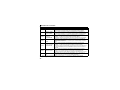
1.1
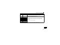
Inverter model
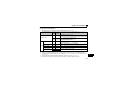
The inverter models 55K and 75K stated in this Instruction Manual differs according to each -NA, -EC, -CHT
versions. Refer to the following correspondence table for each inverter model. (Refer to the instruction
manual of each inverter for the inverter type.)
For example, "for the 75K or higher" indicates "for the FR-A740-01440-NA or higher" in the case of
FR-A740 of NA version.
NA
A700
FR-A720-55K
FR-A720-75K
FR-A740-55K
FR-A740-75K
FR-A720-02150-NA
FR-A720-02880-NA
FR-A740-01100-NA
FR-A740-01440-NA
EC
⎯
⎯
FR-A740-01800-EC
FR-A740-02160-EC
CHT
⎯
⎯
FR-A740-55K-CHT
FR-A740-75K-CHT
1
1
PRE-OPERATION INSTRUCTIONS
1.2
Unpacking and product confirmation
Take the plug-in option out of the package, check the product name, and confirm that the product is as you
ordered and intact.
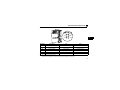
This product is a plug-in option for the FR-A700 series manufactured in April 2011 or later.
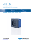
z SERIAL number check
Refer to the inverter manual for the location of the rating plate.
Rating plate example
Symbol
1
Year
4
Month
{{{{{{
Control number
SERIAL
The SERIAL consists of one symbol, two characters indicating production year and month,
and six characters indicating control number.
The last digit of the production year is indicated as the Year, and the Month is indicated by
1 to 9, X (October), Y (November), or Z (December).
2
PRE-OPERATION INSTRUCTIONS
1.2.1
Product confirmation
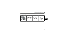
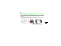
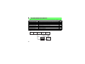
Check the enclosed items.
Plug-in option ................... 1 Mounting screw (M3 × 6mm) Hex-head screw for option Communication option LED
.............. 4 (Refer to page 9.) mounting (5.5mm) ............ 2 display cover ................... 1
(Refer to page 9.)
(Refer to page 8.)
5.5mm
1
5.5mm
3
PRE-OPERATION INSTRUCTIONS
1.3
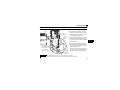
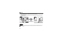
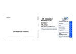
Parts
Connector for communication (PORT1)
For an Ethernet cable which connects to the network. (Refer to page 16)
Front view
Mounting
hole
Rear view
Mounting
hole
Mounting
hole
Mounting
hole
Operation status indication LED
Lit/flicker of the LED indicate operation status.
(Refer to page 5)
Connector
Connect to the inverter option connector.
Connector for communication (PORT2)
For an Ethernet cable which connects to the network. (Refer to page 16)
4
PRE-OPERATION INSTRUCTIONS
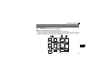
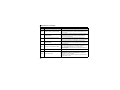
•Operation status LEDs
RUN-
LED name
*1
*2
Description
-D.LINK
SD-
-ERR
RD-
-L.ERR
ON
RUN
Operation status
SD
RD
Transmission status
Reception status
Normal operation (normal 5V
internal voltage) *1
Data transmitting
Data receiving
D.LINK
Cyclic communication status
Cyclic transmitting
ERR
L.ERR
Node failure status *2
Link error
Node failure
Received data error
1
OFF
Hardware failure
No data transmitting
No data receiving
No cyclic transmitting or
disconnected
Normal operation
Received data normal
Also lit in no-communication state.
This LED indicates a communication break between the master station and FR-A7NCE (due to cable
disconnection or breakage, power-OFF of the master power supply, or reset, etc.)
5
PRE-OPERATION INSTRUCTIONS
1.4 CC-Link IE Field Network communication specifications
Type
Power supply
Transmission speed
Communication
method
Number of units
connected
Maximum distance
between nodes
Maximum number of
branches
Topology
Connection cable
Connector
Node type
6
Inverter plug-in option type, RJ-45 connector connection method
5VDC supplied from the inverter
1Gbps
Token passing
120 units at max. (64 units when all stations are inverters handling 128-word transmissions.)
Different devices can be connected together.
100m
No upper limit within the same Ethernet system
Line, star, ring, or a combination of line and star
Ethernet cable
(IEEE 802.3 1000BASE-T compliant cable
or ANSI/TIA/EIA-568-B (Category 5e) compliant shielded 4-pair branched cable)
Shielded RJ-45
RX
64 bits
RY
64
bits
Maximum cyclic size (of one
node)
Intelligent device station
RWr
128 words
RWw
128 words
Transient transmission
Not available
2
INSTALLATION
2.1
Pre-installation instructions
Make sure that the input power of the inverter is OFF.
CAUTION
With input power ON, do not install or remove the plug-in option. Otherwise, the inverter and
plug-in option may be damaged.
For prevention of damage due to static electricity, touch nearby metal before touching this
product to eliminate static electricity from your body.
2
7
INSTALLATION
2.2
Installation of the communication option LED display cover
Mount the cover for displaying the operation status indication LED for the communication option on the
inverter front cover.
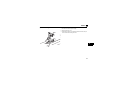
1)Cut off hooks on the rear of the inverter front
cover with nipper, etc. and open a window for
fitting the LED display cover.
2)Fit
the communication option LED display
cover to the front of the inverter front cover
and push it into until fixed with hooks.
Cut off with a nipper, etc.
Fit it so that the position of
lenses is in the upper-right
of the LED display cover.
When attached
Cut off with a nipper, etc.
CAUTION
Take caution not to hurt your hand and such with portions left by cutting hooks of the rear of
the front cover.
8
INSTALLATION
2.3
Installation procedure
1) Remove the inverter front cover.
1)
Screw hole for
option mounting
Inverter side
option
connector 3
3)
Screw hole for
option mounting
(on earth plate)
2) Mount the hex-head screw for option
mounting into the inverter screw hole
(on earth plate) (Size 5.5mm, tightening
torque 0.56Nxm to 0.75Nxm).
3) Securely fit the connector of the plug-in
option to the inverter connector along
the guides. Occupies space equivalent
to two option units.
4) Securely fix four points of the plug-in
option to the inverter with the accessory
mounting screws. (Tightening torque
0.33Nxm to 0.40Nxm)
If the screw holes do not line up, the
connector may not have been plugged
securely. Check for loose plugging.
2)
Hex-head screw
for option mounting
4) Mounting
screws
REMARKS
• Remove a plug-in option after removing four screws on both left and right sides.
(The plug-in option is easily removed if the control circuit terminal block is removed before.)
9
2
INSTALLATION
CAUTION
•
When using this option unit, mount it in the "option connector 3 (lowermost
connector)" of the inverter.
If it is fitted in option connector 1 or 2, "
" or "
" (option fault) is
displayed and the inverter will not function. In addition, when the inverter
cannot recognize that the option is mounted due to improper installation, etc.,
•
•
•
•
Mounting
Position
Fault
Display
Connector 1
Connector 2
"
" (option fault) is displayed even if the option is fitted in the option
Connector 3
connector 3.
This option unit requires space equivalent to two option units. Only one option can be used at a time. For
other option units, mount it in the option connector 1. They cannot be connected in the option connector 2.
When mounting/removing an option, hold the sides of the circuit board. Do not press on the parts on the
circuit board. Stress applied to the parts by pressing, etc. may cause a failure.
Take care not to drop a hex-head screw for option mounting or mounting screw during mounting and removal.
Pull out the option straight to remove. Pressure applied to the connector and to the circuit board may break
the option.
10
3
WIRING
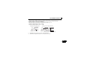
3.1 System configuration example
(1) Programmable controller side
Mount the "QJ71GF11-T2" "CC-Link IE Field Network master/local module" on the main or extension
base unit having the programmable controller CPU used as the master station.
(2) Inverter side
Mount the option (FR-A7NCE) on the inverter.
(3) Connect the CC-Link IE Field Network programmable controller (master station) to FR-A7NCE with an
Ethernet cable. Connect an Ethernet cable, then remove the front cover.
Intelligent device station
Instruction manual regarding
the CC-Link IE Field Network
master station
Master station
QJ71GF11-T2
Inverter
Inverter
Up to 120
units can be
connected
QJ71GF11-T2 type
MELSEC-Q CC-Link IE Field Network
Master/Local Module User's Manual
SH-080917ENG
3
Ethernet cable
Power
supply
Motor
Power
supply
Motor
11
WIRING
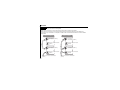
3.2 Network configuration
(1) Network topology
The network can be wired into star topology, line topology, and ring topology.
A network can consist of a combination of star and line topologies, but the ring topology cannot be
combined with star or line topology.
Item
Star topology
Line topology
Ring topology
12
Description
The network is configured into a star using a switching hub and Ethernet cables. Slave
stations can be easily added to the network using this topology. (Add/remove slave stations one by
one. If multiple slave stations are added/removed at a time, all stations on the network will be
reconnected, and an error may momentarily occur in all the stations.)
The network is configured into a line by connecting the modules with Ethernet cables, but without a
switching hub.
The network is configured into a ring using Ethernet cables, but without a switching hub.
Data link continues with the stations that are operating normally.
WIRING
(2) Station number and connection position
Modules can be connected in any order regardless of the station number.
(3) Cascade connection
Up to 20-layer connection is available for the cascade connection.
(4) Replacing CC-Link IE Field Network devices
For star topology, slave stations can be replaced without powering off the whole system.
REMARKS
⋅ Refer to the MELSEC-Q CC-Link IE Field Network Master/Local Module User's Manual for the detailed network
configurations.
3
13
WIRING
3.3 Network components
This section describes components comprising the CC-Link IE Field Network.
3.3.1
Connection cable
For wiring, use the 1000BASE-T compliant Ethernet cables.
Ethernet cable
Category 5e or higher
(Double shielded/STP) Straight cable
Connector
RJ-45 connector
Type
The following conditioning cables:
⋅ IEEE802.3 (1000BASE-T)
⋅ ANSI/TIA/EIA-568-B (Category 5e)
CAUTION
⋅ For CC-Link IE Field Network wiring, use the recommended wiring components by CC-Link Partner Association.
⋅ Cables for CC-Link IE Controller Network cannot be used for CC-Link IE Field Network.
14
WIRING
3.3.2
Hubs
Use hubs that meet the conditions listed below:
⋅ Compliance with the IEEE802.3 (1000BASE-T)
⋅ Support of the auto MDI/MDI-X function
⋅ Support of the auto-negotiation function
⋅ Switching hub (layer 2 switch) *
Operation is not guaranteed if the hubs do not meet these conditions.
* A repeater hub is not available.
Industrial switching hub
Type
Manufacturer
NZ2EHG-T8
Mitsubishi Electric Corporation
3
15
WIRING
3.4 Wiring
This section describes the cable wiring and precautions. For network configuration, cables, and hubs used
for the wiring, refer to page 12 and subsequent pages.
3.4.1
Ethernet cable connection
(1) Connecting the cable
1. Turn OFF the inverter power supply.
2. Remove the front cover.
3. Check the direction of the Ethernet cable connector.
Insert the connector to the communication connector of FRA7NCE until it clicks.
16
WIRING
(2) Disconnecting the cable
1. Turn OFF the inverter power supply.
2. Remove the front cover.
3. Hold down the latch on the Ethernet cable connector, and pull
out the cable while holding the latch.
3
17
WIRING
REMARKS
PORT1 and PORT2 do not need to be distinguished.
⋅ When only one connector is used in star topology, either PORT1 or PORT2 is applicable.
⋅ When using two connectors for line topology and ring topology, an Ethernet cable can be connected to the
connectors in any combination. For example, the cable can be connected between PORT1s or between PORT1
and PORT2.
Connection between
PORT1s or PORT2s
Connector for
communication (PORT1)
Connector for communication
(PORT2)
Connector for
communication (PORT1)
Connector for communication
(PORT2)
To the next connector for communication
(PORT2)
18
Connection between
PORT1 and PORT2
Connector for
communication (PORT1)
Connector for communication
(PORT2)
Connector for
communication (PORT1)
Connector for communication
(PORT2)
To the next connector for communication
(PORT2)
WIRING
3.4.2
Precautions
This section describes wiring precautions.
(1) Handling of the Ethernet cable
⋅ Do not touch the core of the cable-side or module-side connector, and protect it from dirt or dust. If
oil from your hand, dirt or dust is attached to the core, it can increase transmission loss, arising a
problem in data link.
⋅ Check the following:
⋅ Is any Ethernet cable disconnected?
⋅ Is any of the Ethernet cables shorted?
⋅ Are the connectors securely connected?
(2) Broken cable latch
Do not use Ethernet cables with broken latches. Doing so may cause the cable to unplug or
malfunction.
3
(3) Connecting and disconnecting the Ethernet cable
Hold the connector part when connecting and disconnecting the Ethernet cable. Pulling a cable
connected to the module may damage the module or cable, or result in malfunction due to poor contact.
(4) Maximum station-to-station distance (maximum cable length)
The maximum station-to-station distance is 100m. However, the distance may be shorter depending
on the operating environment of the cable. For details, contact your cable manufacturer.
19
WIRING
(5) Network configuration
Check the instructions on page 12 before wiring, and perform correct wiring.
(6) For wiring of the inverter which has one front cover, remove a hook of the front cover, and use the space
that becomes available.
For wiring of the inverter which has front cover 1 and 2, use the space on the left side of the control
circuit terminal block.
Front cover
Ethernet
cable
Inverter which has one front cover
Cut off
with a
nipper,
etc.
Cut off a hook on the inverter
front cover side surface.
(Cut off so that no portion is left.)
Front cover 1
Front cover 2
Ethernet cable
Control circuit
terminal block
Inverter which has front cover 1 and 2
REMARKS
⋅ When the hook of the inverter front cover is cut off for wiring, the protective structure (JEM1030) changes to open
type (IP00).
⋅ When using an option other than FR-A7NCE, connect the other option’s cable to the option connector 1, then
connect FR-A7NCE.
20
WIRING
CAUTION
When installing 3.7K or lower inverter, keep 5cm or more clearance between
the inverter left and the other equipment or enclosure surface. This
clearance is necessary to wire the Ethernet cable. (Refer to the inverter manual
for more installation conditions. )
5cm
or more
When performing wiring using the space between the inverter front cover and
control circuit terminal block, take caution not to subject the cable to stress.
After wiring, wire offcuts must not be left in the inverter. They may cause an error, failure or
malfunction.
3
21
4
INVERTER SETTING
4.1 Parameter list
The following parameters are used for the plug-in option (FR-A7NCE).
Set the values according to need.
Parameter
Number
79
313 *1
314 *1
315 *1
338
339
340
342
349 *1
434*1, *2
435*1, *2
500 *1
501 *1
502 *1
541 *1
550 *2
804
*1
*2
*3
22
Name
Setting Range
Operation mode selection
DO0 output selection
DO1 output selection
0 to 4, 6, 7
0 to 8, 10 to 20, 25 to 28, 30 to 36,
39, 41 to 47, 64, 70 to 78, 84 to 99,
100 to 108, 110 to 116, 120, 125 to
128, 130 to 136, 139, 141 to 147,
DO2 output selection
164, 170, 184 to 199, 9999
Communication operation command source
0, 1
Communication speed command source
0, 1, 2
Communication startup mode selection
0, 1, 2, 10, 12
Communication EEPROM write selection
0, 1
Communication reset selection
0, 1
Network number (CC-Link IE)
0 to 255
Station number (CC-Link IE)
0 to 255
Communication error execution waiting time
0 to 999.8s
Communication error occurrence count display
0
Stop mode selection at communication error
0 to 3
Frequency command sign selection (CC-Link)
0, 1
NET mode operation command source selection
0, 1, 9999
Torque command source selection
0 to 6
Parameters which can be displayed when the plug-in option (FR-A7NCE) is mounted.
The setting is reflected after inverter reset or at the next power-ON.
Refer to Chapter 4 of the inverter manual for the parameter details.
Minimum
Refer
Initial
Setting
to
Value
Increments
Page
1
0
23
1
9999
49
1
1
1
1
1
1
1
0.1s
1
1
1
1
1
0
0
0
0
0
0
0
0
0
0
0
9999
0
*3
*3
23
*3
32
33
33
26
27
28
34
*3
64
INVERTER SETTING
4.2
Operation mode setting
4.2.1
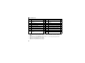
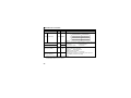
Operation mode switching and communication startup mode (Pr. 79, Pr. 340)
(1) Operation mode switching conditions
Before switching the operation mode, check that:
1) The inverter is at a stop;
2) Both the STF and STR signals are OFF; and
3) The Pr. 79 Operation mode selection setting is correct.
(Set with the operation panel of the inverter.)
Refer to the Inverter Manual for details of Pr. 79.
(2) Operation mode selection at power ON and at restoration from instantaneous power failure
The operation mode at power ON and at restoration from instantaneous power failure can be selected.
Set a value other than "0" in Pr. 340 to select the Network operation mode.
After started in Network operation mode, parameter write from the network is enabled. (Refer to page 75 for
a program example for parameter write.)
REMARKS
⋅ Change of the Pr. 340 setting is valid when powering ON or resetting the inverter.
⋅ Pr. 340 can be changed with the operation panel in any operation mode.
23
4
INVERTER SETTING
Pr. 340
Setting
Pr. 79
Setting
0 (initial
value)
1
0
(initial
value)
2
3, 4
6
Operation Mode at Power ON or Power
Restoration
External operation mode
PU operation mode
External operation mode
External/PU combined operation mode
External operation mode
Operation Mode Switchover
Switching among the External, PU, and NET operation mode is
enabled *1
PU operation mode fixed
Switching between the External and NET operation mode is enabled
Switching to the PU operation mode is disallowed
Operation mode switching is disallowed
Switching among the External, PU, and NET operation mode is enabled
while running.
Switching among the External, PU, and NET operation mode is enabled
X12 (MRS) signal ON ..... External operation
*1
mode
X12 (MRS) signal OFF ... External operation
External operation mode fixed (Forcibly switched to External
mode
operation mode.)
0
NET operation mode
1
PU operation mode
2
NET operation mode
3, 4
External/PU combined operation mode
Same as when Pr. 340 = "0"
1, 2 *2
6
NET operation mode
X12 (MRS) signal ON .... NET operation mode
7
X12 (MRS) signal OFF ... External operation
mode
0
NET operation mode
Switching between the PU and NET operation mode is enabled *3
1
PU operation mode
Same as when Pr. 340 = "0"
2
NET operation mode
NET operation mode fixed
10, 12 *2
3, 4
External/PU combined operation mode
Same as when Pr. 340 = "0"
Switching between the PU and NET operation mode is enabled while running *3
6
NET operation mode
7
External operation mode
Same as when Pr. 340 = "0"
*1 Operation mode cannot be directly changed between the PU operation mode and Network operation mode.
*2 The Pr. 340 settings "2, 12" are mainly used for communication operation using the inverter RS-485 terminal.
Even if an instantaneous power failure occurs while Pr.57 Restart coasting time ≠ "9999", the inverter continues running at the condition before
the instantaneous failure.
When Pr.340 = "1, 10", a start command turns off if power failure has occurred and then restored during a start command is on.
7
*3 Operation mode can be changed between the PU operation mode and Network operation mode with
(FR-DU07) and X65 signal.
24
on the operation panel
INVERTER SETTING
(3) Operation mode switching method
When "0, 1, or 2" is set in Pr. 340
External operation
Switching with the PU
Switching through the network
Switch to the External
operation mode through
the network.
Press
Switch to the Network operation
mode through the network.
Press
the PU to light
Network operation
When "10 or 12" is set in Pr. 340
PU to light
on
on the
.
.
PU operation
Press of on the PU to light
.
Network operation
4
PU operation
Press of on the PU to light
.
For the switching method with the external terminal, refer to the Inverter Manual.
Refer to page 57 for a switching method through the network.
CAUTION
⋅ When starting the inverter in the Network operation mode at power ON or an inverter reset, set a value other than 0
in Pr. 340. (Refer to page 23)
⋅ When setting a value other than 0 in Pr. 340, make sure that the initial settings of the inverter are correct.
25
INVERTER SETTING
4.3
Operation at communication error occurrence
4.3.1
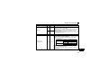
Operation selection at communication error occurrence (Pr. 500 to Pr. 502)
You can select operations at communication error occurrences by setting Pr. 500 to Pr. 502 under Network
operation.
(1) Waiting time for the communication line error output after a communication error
Waiting time for the communication error output after a communication line error occurrence can be
set.
Parameter
Number
Name
Setting Range
Minimum Setting
Increments
Initial Value
500
Communication error
execution waiting time
0 to 999.8s
0.1s
0
Communication line status
Communication error
(E.OP3)
Alarm signal (LF)
(Pr. 502 = 3)
Normal
Error
Normal
Error
Recognition
Pr. 500
setting time
Pr. 500
setting time
ON
When a communication line error occurs and lasts longer than the time set in Pr. 500, it is recognized
as a communication error.
If the communication returns to normal within the time, it is not recognized as a communication error,
and the operation continues.
26
INVERTER SETTING
(2) Displaying and clearing the communication error count
The cumulative count of communication error occurrences can be displayed.
Write "0" to clear this cumulative count.
Parameter
Number
Name
Setting Range
Minimum Setting
Increments
Initial Value
501
Communication error
occurrence count display
0
1
0
Count timing depending on
communication line status
Normal
Error
Normal
Incremented by 1
Error
Incremented by 1
At the point of communication line error occurrence, Pr. 501 Communication error occurrence count
display is incremented by 1.
CAUTION
⋅ Communication error count is temporarily stored in the RAM memory. The error count is stored in EEPROM
only once per hour. If power reset or converter reset is performed, Pr. 501 setting will be the one that is last
stored to EEPROM depending on the reset timing.
27
4
INVERTER SETTING
(3) Inverter operation at a communication error occurrence
How the inverter operates at a communication line error or an option unit fault can be set.
Parameter
Number
Name
Setting Range
Minimum Setting
Increments
Initial Value
502
Stop mode selection at
communication error
0, 1, 2, 3
1
0
About setting
zOperation at an error occurrence
Error Definition
Communication line
Communication
option itself
Pr. 502 Setting
0
1
2
3
0, 3
1, 2
Operation
Indication
Fault Output
Continued *
Normal indication *
Not provided *
Coast to stop
Decelerated to stop
E. 3 lit
E. 3 lit after stop
Provided
Provided after stop
* When the communication returns to normal within the time period set in Pr. 500, the communication option error (E.OP3)
does not occur.
zOperation at error detection after elapse of Pr. 500 time
Error Definition
Communication line
Communication
option itself
28
Pr. 502 Setting
Operation
Indication
Fault Output
0
1
2
3
0, 3
1, 2
Coast to stop
E.OP3 lit
Decelerated to stop
E.OP3 lit after stop
Provided
Provided after stop
Continued
Coast to stop
Decelerated to stop
Normal indication
E.3 lit
E.3 lit after stop
Not provided
Provided
Provided after stop
INVERTER SETTING
zOperation at error removal
Error Definition
Communication line
Communication
option itself
Pr. 502 Setting
0
1
2
3
0, 3
1, 2
Operation
Indication
Fault Output
Kept stopped
E.OP3 kept lit
Kept provided
Restart
Continued
Normal indication
Not provided
Kept stopped
E.3 kept lit
Kept provided
CAUTION
⋅ Communication line error [E.OP3 (fault data: HA3)] is an error that occurs on the communication line.
Communication option error [E. 3 (fault data: HF3)] is an error that occurs in the communication circuit inside the
option.
⋅ Fault output indicates the fault output signal (terminal ABC1) and fault bit output.
⋅ When the fault output setting is active, fault records are stored in the faults history.
⋅ When the fault output setting is not active, fault record is overwritten to the faults history temporarily but not stored.
After the error is removed, the fault indication is reset, changing the display back to normal, and the last fault is
displayed in the faults history.
⋅ When the Pr. 502 setting is "1" or "2", the deceleration time is the ordinary deceleration time setting (e.g. Pr. 8, Pr. 44,
Pr. 45).
⋅ The acceleration time at a restart is the ordinary acceleration time setting (e.g. Pr. 7, Pr. 44).
⋅ When the Pr. 502 setting is "2", the operation/speed command at a restart is the one given before the error
occurrence.
⋅ When a communication line error occurs at the Pr. 502 setting of "2", removing the error during deceleration causes
acceleration to restart at that point. (Acceleration is not restarted if the error is that of the option unit itself.)
29
4
INVERTER SETTING
4.3.2
Fault and measures
(1) The inverter operates as follows at fault occurrences.
Fault
Location
Status
Inverter operation
Data communication
Communication Inverter operation
line
Data communication
Communication option
connection error
Communication
Error of
option
communication option
itself
Network
Operation
Operation Mode
External
PU Operation
Operation
Inverter operation
Data communication
Inverter operation
Inverter trip
Continued
Inverter trip*
Stop
Inverter trip*
Continued
Inverter trip*
Inverter trip
Continued
Continued
Stop
Inverter trip*
Continued
Continued
Inverter trip
Continued
Continued
Stop
Inverter trip*
Continued
Continued
Data communication
Stop
Stop
Stop
Inverter
* Depends on the Pr.502 setting.
(2) Measures at error occurrences
Fault Indication
E.OP3
E.1, E.2, E.3
Error Definition
Communication line
error
Option fault
Measures
Check the LED status of the option unit and remove the cause of the
alarm. (Refer to page 5 for LED indication status)
Inspect the master.
Check the connection between the inverter and option unit for poor
contact, etc. and remove the cause of the error.
Fit the communication option in the option connector 3.
* When faults other than the above are displayed, refer to the inverter manual and remove the cause of the error.
30
INVERTER SETTING
4.4
Inverter reset
(Refer to page 79 for an inverter reset programming example.)
(1) Operation conditions of inverter reset
Which resetting method is allowed or not allowed in each operation mode is described below.
Resetting Method
Inverter reset (Refer to page 60) *1
Reset from the
Error reset (RY3A) at inverter fault
network
(Refer to page 46) *2
Network
Operation
Allowed
Pr.349 = 0
Pr.349 = 1
Allowed
Turn ON the inverter RES signal (terminal RES)
Allowed
Switch OFF inverter power
Allowed
Allowed
Reset from the Inverter reset
PU/DU
Reset at inverter fault
Allowed
*1 Inverter reset can be made any time.
*2 Reset can be made only when the protective function of the inverter is activated.
Operation Mode
External
PU
Operation
Operation
Disallowed
Disallowed
Allowed
Allowed
Disallowed
Disallowed
Allowed
Allowed
Allowed
Allowed
Allowed
Allowed
Allowed
Allowed
4
CAUTION
⋅ When a communication line error has occurred, reset cannot be made from the network.
⋅ The inverter is set to the External operation mode if it has been reset in Network operation mode in the initial status.
To resume the network operation, the inverter must be switched to the Network operation mode again.
Set a value other than "0" in Pr. 340 to start in the Network operation mode. (Refer to page 23.)
⋅ Communication continues during inverter reset. (The inverter cannot be controlled for about 1s after release of a
reset command .)
31
INVERTER SETTING
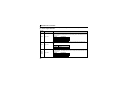
(2) Error reset operation selection at inverter fault
When an inverter is used with a communication option, an error reset command* from network can be
set invalid in the External operation mode or PU operation mode.
Parameter
Number
349
Name
Communication reset
selection
* RY3A (Refer to page 46)
32
Initial
Value
Setting
Range
0
0
1
Function
Error reset* is enabled independently of
operation mode
Error reset* is enabled only in the network
operation mode
INVERTER SETTING
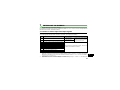
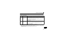
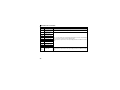
4.5 CC-Link IE Field Network function setting
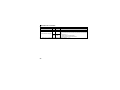
4.5.1 Network number setting (Pr.434)
Set the inverter network number in Pr.434.
Parameter Number
434
Name
Network number (CC-Link IE)
Initial Value
Setting Range
0
0 to 255*
* The setting range of Pr.434 is "0 to 255", but its active range is "1 to 239". The values out of the active range are invalid
because such values cannot be transmitted to the master station.
4.5.2
Station number setting (Pr. 435)
Use Pr. 435 to set station number of the inverter.
Parameter Number
435
Name
Station number (CC-Link IE)
Initial Value
Setting Range
0
0 to 255*
* The setting range of Pr.435 is "0 to 255", but its active range is "1 to 120". The values out of the active range are invalid
because such values cannot be transmitted to the master station.
4
CAUTION
⋅ Use different station numbers for different devices. (If different devices have the same station number, the
communication cannot be performed properly. )
REMARKS
⋅ Station numbers do not have to be consecutive numbers.
⋅ The setting is applied after an inverter reset or power-ON.
33
INVERTER SETTING
4.5.3
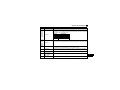
Frequency command with sign (Pr.541)
By frequency command with sign, start command (forward rotation/reverse rotation) can be inversed to operate.
Make selection of sign for the frequency command from RWw0.
Parameter Numbers
Name
Initial Value Setting Range
541
Speed Setting Using
Pr.37 and Pr.144
Not used
With
Frequency command sign selection (CC-Link)
0
Pr.541
Setting
Sign
Setting Range
0
1
0
1
Not used
With
Not used
With
0 to 40000
-32768 to 32767 (two's complement)
0 to 65535
-32768 to 32767 (two's complement)
0, 1
Actual Frequency Command
0 to 400.00Hz
-327.68 to 327.67Hz
It depends on Pr.37, Pr.144, Pr.811.
(in 1 or 0.1 increments)
Relationship between the start command and sign (Pr.541 = "1")
Start command Sign of the Frequency Command Actual Run Command
Forward rotation
Reverse rotation
+
+
-
Forward rotation
Reverse rotation
Reverse rotation
Forward rotation
REMARKS
⋅ When Pr.541 = 1 (with sign)
⋅ When EEPROM write is specified with the RY22, write mode error (error code H01) will occur.
⋅ When both RY21 and RY22 are turned ON, RY21 has precedence.
⋅ When power is turned ON (inverter reset), the initial setting status of the sign bit is "positive" and the set
frequency is "0Hz". (EEPROM value is not reflected.)
Note that if the operation mode when power is turned ON (inverter reset) is PU or External/PU combined
operation mode 1 (Pr.79 = 1, 3), the set frequency is EEPROM value.
⋅ When set frequency is written with the instruction code of HED and HEE, the sign of the frequency command is not
changed.
⋅ Setting "1 or 11" in Pr.811 Set resolution switchover changes the increments from 1r/min to 0.1r/min.
34
5
FUNCTION OVERVIEW
5.1 Output from the inverter through the network
Main items which can be output from the inverter to the master and their descriptions are explained below.
Item
Description
Refer to Page
Inverter status monitor
The output terminal status of the inverter can be
monitored.
Output frequency monitor
The output frequency can be monitored.
Output current monitor
The output current can be monitored.
57
Output voltage monitor
The output voltage can be monitored.
57
Special monitor
The monitor data selected can be checked.
57
Faults history
Fault records can be checked.
Data at alarm occurrence
The inverter status at alarm occurrence can be checked.
55
Operation Mode
The current operation mode can be checked.
57
Parameter read
Parameter settings can be read.
59
Read of set frequency (torque command) The current set frequency (torque command) can be read.
47
56, 57
55, 58
58
5
REMARKS
⋅ Refer to the inverter manual for functions controllable through the network in each operation mode.
35
FUNCTION OVERVIEW
5.2 Input to the inverter through the network
Main commands which can be input from the master to the inverter and their descriptions are explained
below.
Item
Description
Refer to Page
Forward rotation command
Give the forward rotation command.
45
Reverse rotation command
Give the reverse rotation command.
45
Input terminal function command
Execute functions assigned to the inverter input terminals.
45
Inverter output stop command
Stop the inverter output.
45
Error reset
Reset the inverter only when an inverter alarm occurs.
46
Frequency setting (torque command)
Set the frequency (torque command).
51, 58
Monitor command
Specify the description monitored.
53, 57
Operation mode specification
Set the operation mode.
57
Faults history clear
Erase past eight fault records.
59
All parameter clear
Return the parameter descriptions to the initial value.
59
Inverter reset
Reset the inverter.
60
Parameter write
Write parameter settings.
59
PID control
PID set point, PID measured value and PID deviation can
be input from the network.
52
REMARKS
⋅ Refer to the inverter manual for functions controllable through the network in each operation mode.
36
FUNCTION OVERVIEW
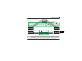
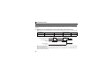
5.3 Cyclic transmission
Data communication is available periodically among stations on the same network. Link devices (RX, RY,
RWr, and RWw) are used.
5.3.1
Data flow and link device assignment
●Master and slave stations (except for local stations)
One-to-one communication is possible between the master and slave stations.
The status information of the link devices (RY and RWw) of the master station is output to the external
device of the slave station, and the input status information from the external device of the slave station
is stored in the link devices (RX and RWr) of the master station.
CPU
module
Station No.0
Station No.1
Station No.2
Master
station
Slave station
Slave station
RX, RWr
RX, RWr
5
Device
7
EN
D
Sequence
scan
Link refresh
5
Station
No.1
6
Station
No.2
6
Station No.1
RX, RWr
Station No.2
5
Link
scan
4
Device
RY, RWw
2
EN
D
Sequence
scan
M0
Y
Link refresh
1
RY, RWw
Station
No.1
3
Station
No.2
3
Station No.1
4
RY, RWw
Station No.2
Area for sending to
other stations
37
FUNCTION OVERVIEW
⋅ Output from the master station
1
2
3
4
The device of the CPU module turns ON.
The device status data of the CPU module are stored in the link devices (RY and RWw) of the
master station by link refresh.
The status data of the link devices (RY and RWw) of the master station are stored in the link
devices (RY and RWw) of each slave station by link scan.
The inverter starts according to the link device (RY and RWw) conditions (input signals such as
STF and STR) of the slave station.
⋅ Input from the slave station
Inverter conditions (output signals such as RUN and SU, monitoring) are stored in the link
5
devices (RX and RWr) of the slave station.
The status data of the link devices (RX and RWr) of the slave station are stored in the link
6
devices (RX and RWr) of the master station by link scan.
The status data of the link devices (RX and RWr) of the master station are stored in the devices
7
of the CPU module by link refresh.
REMARKS
⋅ Refer to the MELSEC-Q CC-Link IE Field Network Master/Local Module User's Manual for the detailed assignment
methods for the link devices and link refresh.
38
6
I/O SIGNAL LIST
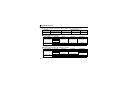
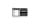
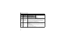
6.1 Remote I/O (64 points fixed)
Device
No.
RYn0
RYn1
RYn2
RYn3
RYn4
RYn5
RYn6
RYn7
RYn8
RYn9
RYnA
RYnB
RYnC to
RYnF
Signal
Forward rotation command
Reverse rotation command
High-speed operation command
(terminal RH function) *1
Middle-speed operation command
(terminal RM function) *1
Low-speed operation command
(terminal RL function) *1
Jog operation command (terminal Jog
function) *1
Second function selection (terminal RT
function) *1
Current input selection (terminal AU
function) *1
Selection of automatic restart after
instantaneous power failure (terminal CS
function) *1
Output stop (terminal MRS function) *1
Start self-holding selection (terminal
STOP function) *1
Reset (terminal RES function) *1
RY(n+1)0 Reserved
to
RY(n+1)2
Refer
to
Page
Device
No.
45
45
RXn0
RXn1
Forward running
Reverse running
47
47
45
RXn2
Running (terminal RUN function) *2
47
45
RXn3
Up to frequency (terminal SU function) *2
47
45
RXn4
Overload alarm (terminal OL function) *2
47
Signal
Refer
to
Page
45
RXn5
45
RXn6
Instantaneous power failure (terminal IPF
function) *2
Frequency detection (terminal FU
function) *2
45
RXn7
Error (terminal ABC1 function) *2
47
45
RXn8
⎯ (terminal ABC2 function) *2
47
RXn9
to
RXnF
Reserved
⎯
47
47
45
45
45
⎯
RX(n+1)0 Pr. 313 assignment function (DO0) *3
RX(n+1)1 Pr. 314 assignment function (DO1) *3
RX(n+1)2 Pr. 315 assignment function (DO2) *3
6
47
47
47
39
I/O SIGNAL LIST
Device
No.
Signal
RY(n+1)3
to
Reserved
RY(n+1)F
RY(n+2)0 Monitor command
RY(n+2)1 Frequency setting command (RAM)
Frequency setting command (RAM,
RY(n+2)2 EEPROM)
RY(n+2)3 Torque command (RAM)
Refer
to
Page
⎯
46
46
46
46
RY(n+2)4 Torque command (RAM, EEPROM)
46
RY(n+2)5 Instruction code execution request
RY(n+2)6
to
Reserved
RY(n+3)9
RY(n+3)A Error reset request flag
46
RY(n+3)B
to
Reserved
RY(n+3)F
⎯
46
⎯
Device
No.
Signal
RX(n+1)3
to
Reserved
RX(n+1)F
RX(n+2)0 Monitoring
RX(n+2)1 Frequency setting completion (RAM)
RX(n+2)2 Frequency setting completion (RAM,
EEPROM)
RX(n+2)3 Torque command setting completed (RAM)
RX(n+2)4 Torque command setting completed
(RAM, EEPROM)
RX(n+2)5 Instruction code execution completion
RX(n+2)6
to
Reserved
RX(n+3)9
RX(n+3)A Error status flag
RX(n+3)B Remote station ready
RX(n+3)C
to
Reserved
RX(n+3)F
Refer
to
Page
⎯
47
48
48
48
48
48
⎯
48
48
⎯
("n" indicates a value determined according to the station number setting.)
*1 These signals are set in the initial status. Using Pr. 180 to Pr .189, you can change input signal functions.
Signals of the RYn0 and RYn1 cannot be changed. Even when changed using Pr. 178 and Pr. 179, the settings are
invalid.
Refer to the inverter manual for details of Pr. 178 to Pr. 189.
*2 These signals are set in the initial status. Using Pr. 190 to Pr .196, you can change output signal functions.
Refer to page 49 for signals which can be assigned.
*3 Output signal can be assigned using Pr. 313 to Pr. 315.
Refer to page 49 for signals which can be assigned.
40
I/O SIGNAL LIST
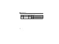
6.2 Remote register (128 words fixed)
Address
RWwn
RWwn+1
RWwn+2
RWwn+3
RWwn+4
RWwn+5
RWwn+6
RWwn+7
to
RWwn+F
RWwn+10
RWwn+11
RWwn+12
RWwn+13
RWwn+14
RWwn+15
RWwn+16
RWwn+17
RWwn+18
RWwn+19
Description
Refer
to
Page
Address
Set frequency (0.01Hz increments)
Reserved
Torque command
Reserved
PID set point (0.01% increments)*1
PID measured value
(0.01% increments)*1
PID deviation (0.01% increments)*1
51
─
51
─
52
RWrn
RWrn+1
RWrn+2
RWrn+3
RWrn+4
Reply code
Reserved
Reply code
Reserved
Reply code
54
─
54
─
54
52
RWrn+5
Reply code
54
52
Reply code
54
Reserved
─
RWrn+6
RWrn+7
to
RWrn+F
Reserved
─
52
RWrn+10
Reply code
55
52
RWrn+11
Read data*2
55
Upper 8 Bits
Lower 8 Bits
Link parameter
Instruction code*2
extended setting
Write data
Link parameter
Instruction code*2
extended setting
Write data
Link parameter
Instruction code*2
extended setting
Write data
Link parameter
Instruction code*2
extended setting
Write data
Link parameter
Instruction code*2
extended setting
Write data
Description
Upper 8 Bits
Lower 8 Bits
Refer
to
Page
52
RWrn+12
Reply code
55
52
RWrn+13
Read data*2
55
52
RWrn+14
Reply code
55
52
RWrn+15
Read data*2
55
52
RWrn+16
Reply code
55
52
RWrn+17
Read data*2
55
52
RWrn+18
Reply code
55
52
RWrn+19
Read data*2
55
41
6
I/O SIGNAL LIST
Address
RWwn+1A
RWwn+1B
RWwn+1C
to
RWwn+1F
RWwn+20
RWwn+21
Description
Upper 8 Bits
Lower 8 Bits
Link parameter
extended setting Instruction code*2
Write data
Refer
to
Page
Address
52
RWrn+1A
Reply code
55
52
Read data*2
55
Reserved
─
Error status
Fault record
(fault data)
Fault record (output frequency)
Fault record (output current)
Fault record (output voltage)
Fault record (energization time)
First monitor value
Second monitor value
Third monitor value
Fourth monitor value
Fifth monitor value
Sixth monitor value
Seventh monitor value
Eighth monitor value
Ninth monitor value
Tenth monitor value
Output frequency
Reserved
output current
output voltage
Reserved
55
Reserved
─
RWrn+1B
RWrn+1C
to
RWrn+1F
RWrn+20
Faults history No.
53
RWrn+21
Reserved
─
RWwn+22
to
RWwn+25
Reserved
─
RWwn+26
RWwn+27
RWwn+28
RWwn+29
RWwn+2A
RWwn+2B
RWwn+2C
RWwn+2D
RWwn+2E
RWwn+2F
Monitor code 1
Monitor code 2
Monitor code 3
Monitor code 4
Monitor code 5
Monitor code 6
Monitor code 7
Monitor code 8
Monitor code 9
Monitor code 10
53
53
53
53
53
53
53
53
53
53
RWwn+30
to
RWwn+34
Reserved
─
42
RWrn+22
RWrn+23
RWrn+24
RWrn+25
RWrn+26
RWrn+27
RWrn+28
RWrn+29
RWrn+2A
RWrn+2B
RWrn+2C
RWrn+2D
RWrn+2E
RWrn+2F
RWrn+30
RWrn+31
RWrn+32
RWrn+33
RWrn+34
Description
Upper 8 Bits
Faults history No.
Lower 8 Bits
Refer
to
Page
55
55
55
55
56
56
56
56
56
56
56
56
56
56
56
56
─
56
56
─
I/O SIGNAL LIST
Address
RWwn+35
to
RWwn+52
Description
Upper 8 Bits
Lower 8 Bits
Reserved
Refer
to
Page
Address
─
RWrn+35
RWrn+36
RWrn+37
RWrn+38
RWrn+39
RWrn+3A
RWrn+3B
RWrn+3C
RWrn+3D
RWrn+3E
RWrn+3F
RWrn+40
RWrn+41
RWrn+42
RWrn+43
RWrn+44
RWrn+45
RWrn+46
RWrn+47
RWrn+48
RWrn+49
RWrn+4A
to
RWrn+4F
RWrn+50
RWrn+51
RWrn+52
Description
Upper 8 Bits
Lower 8 Bits
Refer
to
Page
Frequency setting value
Running speed
Motor torque
Converter output voltage
Regenerative brake duty
Electric thermal relay function load factor
Output current peak value
Converter output voltage peak value
Input power
Output power
Input terminal status
Output terminal status
Load meter
Motor excitation current
Position pulse
Cumulative energization time
Reserved
Orientation status
Actual operation time
Motor load factor
Cumulative power
56
56
56
56
56
56
56
56
56
56
56
56
56
56
56
56
─
56
56
56
56
Reserved
─
Torque command
Torque current command
Motor output
56
56
56
43
6
I/O SIGNAL LIST
Address
RWwn+53
to
RWwn+7F
Description
Upper 8 Bits
Lower 8 Bits
Reserved
Refer
to
Page
Address
─
RWrn+53
RWrn+54
to
RWrn+5D
RWrn+5E
RWrn+5F
to
RWrn+61
RWrn+62
RWrn+63
RWrn+64
RWrn+65
RWrn+66
RWrn+67
to
RWrn+69
RWrn+6A
RWrn+6B
RWrn+6C
RWrn+6D
to
RWrn+7F
Description
Upper 8 Bits
Lower 8 Bits
Refer
to
Page
Feedback pulse
56
Reserved
─
Motor temperature monitor output
56
Reserved
─
Power saving effect
Cumulative saving power
PID set point
PID measured value
PID deviation
56
56
56
56
56
Reserved
─
Option input terminal status 1
Option input terminal status 2
Option output terminal status
56
56
56
Reserved
─
("n" indicates a value determined according to the station number setting.)
*1
*2
44
When Pr. 128 = "50, 51, 60, 61", they are valid.
Instructions will be processed in the order they are received. Thus, the read value of an instruction may differ at
different timings if other writing requests are being made.
7
DETAILS OF I/O SIGNALS
The following device No. are those for station 1.
For stations 2 and later, the device No. are different. (Refer to the master module manual for correspondence
between the device No. and station number)
7.1 Details of remote input and output signals
7.1.1
Output signals (master module to inverter (FR-A7NCE))
The output signals from the master module are indicated. (Input signals to inverter)
Device
No.
Signal
Description
0
1
0
1
: Stop command
: Forward rotation start
: Stop command
: Reverse rotation start
When "1" is set, a start command
is input to the inverter.
When "1" is set in RY0 and RY1,
a stop command is input.
RY0
Forward rotation command *2
RY1
Reverse rotation command *2
RY2
RY3
RY4
RY5
RY6
RY7
High-speed operation command (terminal RH function) *1
Middle-speed operation command (terminal RM function) *1
Low-speed operation command (terminal RL function) *1
Jog operation command (terminal JOG function) *1
Second function selection (terminal RT function) *1
Functions assigned to terminals RH, RM, RL, JOG, RT, AU,
Current input selection (terminal AU function) *1
CS, MRS, STOP and RES are activated.
Selection of automatic restart after instantaneous
power failure (terminal CS function) *1
Output stop (terminal MRS function) *1
Start self-holding selection (terminal STOP function) *1
Reset (RES terminal function) *1
RY8
RY9
RYA
RYB
*1
*2
Signal names are initial values. Using Pr. 180 to Pr .189, you can change input signal functions. Note that some of
signals do not accept a command from the network according to the Pr. 338 and Pr. 339 settings. For example,
RYB reset (terminal RES function) cannot be controlled via network. Refer to the inverter manual for the details of
Pr.180 to Pr.189, Pr.338, and Pr.339.
Signals of the RY0 and RY1 cannot be changed. Even when changed using Pr. 178 and Pr. 179, the settings are
invalid. Refer to the inverter manual for details of Pr. 178 and Pr.179.
45
7
DETAILS OF I/O SIGNALS
Device No.
Signal
Description
When "1" is set in the monitor command (RY20), the monitored value is set in the
RY20
Monitor command remote register RWr26 to 2F, and "1" is set in the monitoring (RX20). While "1" is
set in the monitor command (RY20), the monitored data is always updated.
Frequency setting When "1" is set in the frequency setting command (RY21), the set frequency
RY21
(RWw0) is written to RAM of the inverter. *3
command (RAM)
After the writing completes, "1" is set in the frequency setting completion (RX21).
When "1" is set in the frequency setting command (RY22), the set frequency
Frequency setting (RWw0) is written to RAM and EEPROM of the inverter. After the writing
completes, "1" is set in the frequency setting completion (RX22).
RY22
command
To change the frequency consecutively, be sure to write data only to the inverter
(RAM, EEPROM)
RAM (RY21). Writing to EEPROM frequently will shorten the life of EEPROM.
When "1" is set in the torque command (RY23), the torque command (RWw2) is
Torque command
written to RAM of the inverter.
RY23
After the writing completes, "1" is set in the torque command setting completion
(RAM)
(RX23).
When "1" is set in the torque command (RY24), the torque command value
(RWw2) is written to RAM and EEPROM of the inverter. After the writing
Torque command
completes, "1" is set in the torque command setting completion (RX24).
RY24
To change the torque command value consecutively, be sure to write data only to
(RAM, EEPROM)
the inverter RAM (RY23). Writing to EEPROM frequently will shorten the life of
EEPROM.
When "1" is set in the instruction code execution request (RY25), processes
corresponding to the instruction codes set to RWw10, 12, 14, 16, 18 and 1A are
Instruction code
RY25
executed. "1" is set in the instruction code execution request (RX25) after
execution request completion of instruction codes. When an instruction code execution error occurs,
a value other than "0" is set in the reply code (RWr10, 12, 14, 16, 18 and 1A).
Error reset request When "1" is set in the error reset request flag (RY3A) at an inverter fault, the
RY3A
flag
inverter is reset, then "0" is set in the error status flag (RX3A). *4
*3 While "1" is set in the frequency setting command (RY21), the set frequency (RWw0) is always applied.
*4 Refer to page 31 for operation conditions of inverter reset.
46
DETAILS OF I/O SIGNALS
7.1.2
Input signals (inverter (FR-A7NCE) to master module)
The input signals to the master module are indicated. (Output signals from inverter)
Device
No.
RX0
Forward running
RX1
Reverse running
RX2
RX3
RX4
Running (terminal RUN function) *1
Up to frequency (terminal SU function) *1
Overload alarm (terminal OL function) *1
Instantaneous power failure (terminal
IPF function) *1
Frequency detection (terminal FU
function) *1
Fault (terminal ABC1 function) *1
⎯ (terminal ABC2 function) *2
⎯ (DO0 function) *2
⎯ (DO1 function) *2
⎯ (DO2 function) *2
RX5
RX6
RX7
RX8
RX10
RX11
RX12
*2
Description
0
1
0
1
: Other than forward running (during stop or reverse rotation)
: Forward running
: Other than reverse running (during stop or forward rotation)
: Reverse running
Functions assigned to terminals RUN, SU, OL, IPF, FU, ABC1 and
ABC2 activate.
Refer to page 49 for signals which can be assigned.
Functions assigned to Pr. 313 to Pr. 315 are activated.
Refer to page 49 for signals which can be assigned.
After "1" is set in the monitor command (RY20), and the monitored
value is set in the remote register RWr26 to 2F, "1" is set in this
signal. When "0" is set in the monitor command (RY20), "0" is set
in this signal.
Signal names are initial values. Using Pr. 190 to Pr .196, you can change output signal functions.
Refer to the inverter manual for details of Pr. 190 to Pr.196.
Signals are not assigned in the initial setting.
Refer to Pr. 190 to Pr. 196 of the inverter manual for details of signals.
RX20
*1
Signal
Monitoring
47
7
DETAILS OF I/O SIGNALS
Device
No.
Signal
RX21
Frequency setting completion (RAM)
RX22
Frequency setting completion
(RAM, EEPROM)
RX23
Torque command setting completion
(RAM)
RX24
Torque command setting completion
(RAM, EEPROM)
RX25
Instruction code execution completion
RX3A
Error status flag
RX3B
Remote station ready
48
Description
After "1" is set in the frequency setting command (RY21) and the
set frequency is written to the inverter RAM, "1" is set in this signal.
When "0" is set in the frequency setting command (RY21), "0" is
set in this signal.
After "1" is set in the frequency setting command (RY22) and the set
frequency is written to the inverter RAM and EEPROM, "1" is set in
this signal. When "0" is set in the frequency setting command
(RY22), "0" is set in this signal.
After "1" is set in the torque command (RY23) and the torque
command value is written to the inverter RAM, "1" is set in this signal.
When "0" is set in the torque command (RY23), "0" is set in this signal.
After "1" is set in the torque command (RY24) and the torque
command value is written to the inverter RAM and EEPROM, "1" is
set in this signal. When "0" is set in the torque command (RY24), "0"
is set in this signal.
After "1" is set in the instruction code execution request (RY25) and
the processes corresponding to the instruction codes (RWw10, 12,
14, 16, 18 and 1A) are executed, "1" is set in this signal.
When "0" is set in the instruction code execution request (RY25), "0"
is set in this signal.
When an inverter error occurs (protective function is activated), "1"
is set in this signal.
When the inverter goes into the ready status upon completion of
initial setting after power-on or hardware reset, "1" is set in this
signal. When an inverter error occurs (protective function is
activated), "0" is set in this signal.
The signal is used as an interlock signal during the write to/read
from the master module.
DETAILS OF I/O SIGNALS
zOutput signal list
The following signals can be assigned to RX2 to RX8 and RX10 to RX12 using Pr.190 to Pr.196 and Pr.313
to Pr.315 respectively. Refer to the description of Pr.190 to Pr.196 (output terminal function selection) in the
inverter manual for the signal details.
Setting
Signal
Function
Positive Negative Name
Logic
Logic
0
100
RUN Inverter running
1
101
SU Up to frequency
Instantaneous power failure/
2
102
IPF
undervoltage
3
103
OL Overload alarm
4
104
FU Output frequency detection
Second output frequency
5
105
FU2
detection
6
106
FU3 Third output frequency detection
7
107
RBP Regenerative brake pre-alarm
Electronic thermal O/L relay pre8
108
THP
alarm
10
110
PU PU operation mode
11
111
RY Inverter operation ready
12
112
Y12 Output current detection
13
113
Y13 Zero current detection
14
114
FDN PID lower limit
15
115
FUP PID upper limit
PID forward/reverse rotation
16
116
RL
output
17
⎯
MC1 Electronic bypass MC1
18
⎯
MC2 Electronic bypass MC2
19
⎯
MC3 Electronic bypass MC3
Setting
Signal
Function
Positive Negative Name
Logic
Logic
20
120
BOF Brake opening request
25
125
FAN Fan fault output
26
126
FIN Heatsink overheat pre-alarm
27
127
ORA Orientation complete
28
128
ORM Orientation fault
30
130
Y30 Forward rotation output
31
131
Y31 Reverse rotation output
32
132
Y32 Regenerative status output
33
133
RY2 Operation ready 2
34
134
LS Low speed output
35
135
TU Torque detection
36
136
Y36 In-position
39
139
Y39 Start time tuning completion
41
141
FB Speed detection
42
142
FB2 Second speed detection
43
143
FB3 Third speed detection
44
144
RUN2 Inverter running 2
Inverter running and start
45
145
RUN3
command is on
During deceleration at occurrence
46
146
Y46
of power failure
47
147
PID During PID control activated
64
164
Y64 During retry
49
7
DETAILS OF I/O SIGNALS
Setting
Signal
Function
Positive Negative Name
Logic
Logic
70
170
SLEEP PID output interruption
84
184
RDY Position control preparation ready
85
185
Y85 DC feeding
86
186
Y86 Control circuit capacitor life *
87
187
Y87 Main circuit capacitor life *
88
188
Y88 Cooling fan life *
89
189
Y89 Inrush current limit circuit life *
90
190
Y90 Life alarm
91
191
Y91 Fault output 3 (power-off signal)
Energy saving average value
92
192
Y92
updated timing
Current average value monitor
93
193
Y93
signal
94
194
ALM2 Fault output 2
95
195
Y95 Maintenance timer signal
96
196
REM Remote output
97
197
ER Alarm output 2
98
198
LF
Alarm output
99
199
ALM Fault output
9999
⎯
No function
* These signals cannot be assigned with Pr.190 to Pr.196.
50
DETAILS OF I/O SIGNALS
7.2 Details of remote register
7.2.1 Remote register (master module to inverter (FR-A7NCE))
zRemote register definition
Device No.
Signal
Description
⋅ Specify the set frequency or rotations per minute (machine speed). At this time,
whether to write to RAM or EEPROM is decided with the RY21 and RY22
settings. After setting the set frequency in this register, set "1" in RY21 or RY22 to
write the frequency. After writing of frequency is completed, "1" is set in RX21 or
RWw0
Set frequency *1, *2
RX22 in response to the input command.
⋅ The setting range is 0 to 400.00Hz (0.01Hz increments). Write "40000" when
setting 400.00Hz.
Specify the torque command value. Set Pr.804 Torque command source selection = "1,
3, 5, or 6" to activate this signal under torque control, such as Real sensorless
vector control and vector control. The value is written to the inverter either by RY23
Torque command
RWw2
or RY24. Pr.805 Torque command value (RAM) and Pr.806 Torque command value
value
(RAM,EEPROM) are updated as well. The setting range and setting increments
depend on the Pr.804 setting.
*1 Setting increment differs according to the combination of Pr.37, Pr.144, and Pr.811.
Refer to the inverter manual for the details.
*2 When Pr.541 Frequency command sign selection (CC-Link) = 1, the setting value has either + or -. When the setting
value is negative, the command is inversed from starting command.
Setting range: -327.68Hz to 327.67Hz (-327.68 to 327.67) 0.01Hz increments.
For details refer to page 34.
7
51
DETAILS OF I/O SIGNALS
Device No.
Signal
Description
Set the PID set point
⋅ Input a value 100 times greater than the
RWw4
PID set point *3
Setting range : "0 to 100.00%"
value to be set.
PID measured
Set the PID measured value
For example, input "10000" when setting
RWw5
value *3
Setting range : "0 to 100.00%"
100.00%.
Set the PID deviation.
⋅ Refer to the inverter manual for details of
RWw6
PID deviation *3
Setting range : "-100.00% to 100.00%"
PID control.
Set the instruction code (refer to page 57) for execution of operation mode rewrite,
RWw10,
parameter read/write, error reference, error clear, etc. The instructions are
RWw12,
executed in the following order by setting "1" in RY25 after completing the register
Link parameter
RWw14,
extended setting/
setting: RWw10, 12, 14, 16, 18, then 1A. After completing the execution up to
RWw16,
Instruction code
RWw1A, "1" is set in RX25. Set HFFFF to disable an instruction by RWw10 to 1A.
RWw18,
The first 8 bits are link parameter extended setting.
RWw1A
Example) When reading Pr. 160, instruction code is H0200.
Set the data specified by the instruction code of RWw10, 12, 14, 16, 18 and 1A.
RWw11,
(when required)
RWw13,
RWw10 and 11, 12 and 13, 14 and 15, 16 and 17, 18 and 19, and 1A and 1B
RWw15,
Write data
correspond each other.
RWw17,
Set "1" in RY25 after setting the instruction codes (RWw10, 12, 14, 16, 18 and 1A)
RWw19,
and the corresponding register.
RWw1B
Set "0" when the write code is not required.
*3 When Pr. 128 = "50, 51, 60, 61", they are valid. If the data outside the range is set, the previous setting is retained.
Refer to the inverter manual for details of Pr.128.
52
DETAILS OF I/O SIGNALS
Device No.
RWw21
Signal
Description
Faults history No.*4
Set the individual fault number of the faults history that you want to read. Up to the
8th previous fault can be read.
Last two digits: H00 (most recent fault) to H07 (8th most recent fault)
Set H08 to HFF to make the faults history No. to "0."
RWw26 Monitor code 1*4
RWw27 Monitor code 2*4
RWw28 Monitor code 3*4
Set the monitor code to be monitored. By setting "1" in RY20 after setting, the
RWw29 Monitor code 4*4
specified monitored data is stored in RWr
. (
indicates a register number.
RWw2A Monitor code 5*4
RWw2B Monitor code 6*4
(RWr26 to 2F))
RWw2C Monitor code 7*4
(Refer to page 62 for monitor code details.)
RWw2D Monitor code 8*4
RWw2E Monitor code 9*4
RWw2F Monitor code 10*4
*4 Write data is in hexadecimal, and only two digits are valid. (The upper two digits are ignored.)
7
53
DETAILS OF I/O SIGNALS
7.2.2
Remote register (inverter (FR-A7NCE) to master module)
(1) Remote register definition
Device
No.
Signal
Description
When "1" is set in RY21 or RY22, the following reply codes are set for the frequency
setting command. The setting value "0" is set normally, and a value other than "0" is
set at an error.
RWr0
Reply code
Value
Description
H0000
H0001
H0003
Normal
Write mode fault
Setting range fault
When "1" is set in RY23 or RY24, the following reply codes are set for the torque
command. The setting value "0" is set normally, and a value other than "0" is set at an
error.
RWr2
RWr4,
RWr5,
RWr6
54
Reply code
Value
Description
H0000
H0003
Normal
Setting range fault
When the PID command (RWw4 to RWw6) is set, the following reply code is set for
the PID command. The setting value "0" is set normally, and a value other than "0" is
set at an error.
Reply code
Value
Description
H0000
H0003
Normal
Setting range fault
DETAILS OF I/O SIGNALS
Device
No.
Signal
RWr10,
RWr12,
RWr14,
Reply code
RWr16,
RWr18,
RWr1A
RWr11,
RWr13,
RWr15,
Reply code
RWr17,
RWr19,
RWr1B
RWr20 Error status
Fault record
(fault data)
Fault record
RWr22
(output frequency)
Fault record
RWr23
(output current)
Fault record
RWr24
(output voltage)
RWr21
Description
When "1" is set in RY25, the following reply codes corresponding to the instruction
code RWw10, 12, 14, 16, 18, and 1A are set. The setting value "0" is set normally, and
a value other than "0" is set at an error.
Value
Description
H0000
H0001
H0002
H0003
Normal
Write mode fault
Parameter selection fault
Setting range fault
For a normal reply, the reply data to the instruction specified by the instruction code is
set.
The setting value "0" is set during normal inverter operation, and the corresponding
error code is set at an error. (Refer to page 61 for the error codes.)
The fault data of faults history No. specified by RWw21 is stored in the lower 8bits.
Lower 8 bits of RWw21 will be reverted back to the upper 8 bits.
Output frequency of the faults history No. specified in RWw21 is stored.
Output current of the faults history No. specified in RWw21 is stored.
7
Output voltage of the faults history No. specified in RWw21 is stored.
55
DETAILS OF I/O SIGNALS
Device
No.
RWr25
RWr26
RWr27
RWr28
RWr29
RWr2A
RWr2B
RWr2C
Signal
Fault record
(energization time)
First monitor value
Second monitor
value
Third monitor value
Fourth monitor value
Fifth monitor value
Sixth monitor value
Seventh monitor
value
Eighth monitor value
Ninth monitor value
Tenth monitor value
RWr2D
RWr2E
RWr2F
RWr30
to
Monitor value
RWr7F
56
Description
Energization time of the faults history No. specified in RWw21 is stored.
When "1" is set in RY20, the monitored data specified by the monitor code (RWw
) is
saved. (
indicates a register number (RWw26 to 2F))
Output frequency, output current, and output voltage monitors are held at an inverter
failure.
Fixed monitored data are saved regardless of the RY20 setting.
Output frequency, output current, and output voltage monitors are held at an inverter
failure.
DETAILS OF I/O SIGNALS
7.2.3
Instruction codes
(1) Instruction code definition
Set the instruction code using a remote register (RWw) (Refer to page 51.)
The definition read by the instruction code is stored in the remote register (RWr). (Refer to page 54.)
Item
Read / Code
Write Number
Description
H0000: Network operation mode
H0001: External operation mode, External JOG operation mode
Read
H7B
H0002: PU operation mode, External/PU combined operation modes
1 and 2, PUJOG operation mode
Operation mode
H0000: Network operation mode
Write
HFB
H0001: External operation mode
H0002: PU operation mode (Pr. 79 = "6")
H0000 to HFFFF:
Output frequency
Read
H6F
Running frequency .................0.01Hz increments
*1, *2
Speed (machine speed) .........1 increments *3
H0000 to HFFFF: Output current (hexadecimal)
Output current
Read
H70
Increments 0.01A (55K or lower) / 0.1A (75K or higher) *4
Monitor Output voltage
Read
H71
H0000 to HFFFF: Output voltage (hexadecimal) Increments 0.1V
H0000 to HFFFF: Check the data of the monitor selected by the
Special monitor
Read
H72
instruction code H00F3.
Read
H73
Special monitor
H01 to H3C: Monitor selection data
selection No.
Write
HF3 *5 Refer to monitor code. (Refer to page 62.)
*1 When "100" is set in Pr. 52 DU/PU main display data selection, set frequency is monitored during a stop and output
frequency is monitored during running.
*2 When a value other than 9999 is set in Pr.430 under position control (Pr.800 = 3), pulse monitor is selected.
*3 Displayed increments differ according to the combination of Pr.37, Pr.144, and Pr.811. For the details, refer to the
inverter manual.
*4 The inverter models 55K and 75K differ according to -NA and -EC versions. (Refer to page 1.)
*5 Write data is in hexadecimal, and only two digits are valid. (The upper two digits are ignored.)
57
7
DETAILS OF I/O SIGNALS
Item
Read / Code
Write Number
Description
H0000 to HFFFF: Last two fault records
b15
Monitor Faults history
Read
H74 to
H77
b8 b7
b0
H74 Second most recent fault
Most recent fault
H75 Fourth most recent fault
Third most recent fault
Sixth most recent fault
Fifth most recent fault
H76
H77 Eighth most recent fault
Seventh most recent fault
Refer to the fault data table (page 61)
Set frequency (RAM)
H6D
Read
Set frequency (EEPROM)
H6E
Set frequency (RAM) *6
Write
HED
Set frequency
(RAM and EEPROM) *6
Write
HEE
*6
*7
58
Read set frequency/speed (machine speed) from RAM or EEPROM.
H0000 to HFFFF:
Set frequency .........................0.01Hz increments
Speed (machine speed) .........1 increments *7
Write set frequency/speed (machine speed) to RAM or EEPROM.
⋅ H0000 to H9C40 (0 to 400.00Hz) :
Frequency........0.01Hz increments
⋅ H0000 to H270E (0 to 9998) :
Speed (machine speed)......1 increments *7
⋅ To change the set frequency consecutively, write data to the
inverter RAM. (Instruction code: HED)
Setting from remote registers (RWw0) can be made.
Displayed increments differ according to the combination of Pr.37, Pr.144, and Pr.811.
For the details, refer to the inverter manual.
DETAILS OF I/O SIGNALS
Item
Read / Code
Write Number
Read
H00 to
H63
Write
H80 to
HE3
Write
HF4
Parameter
Faults history batch clear
Description
⋅ Refer to the instruction code in the parameter list in the inverter
manual to read and write as required.
Write to Pr. 77 and Pr. 79 is disabled.
When setting Pr.100 and later, set link parameter extended setting.
⋅ Set 65520 (HFFF0) as a parameter value "8888" and 65535
(HFFFF) as "9999".
⋅ When changing the parameter values frequently, set "1" in Pr. 342
to write them to the RAM. (Refer to Chapter 4 of the inverter manual
for the details of Pr.342.)
H9696: Clears the faults history as a batch.
All parameters return to the initial values.
Whether to clear communication parameters or not can be selected
according to data. ({: Clear, ×: Not clear)
Refer to the inverter manual for parameter clear, all clear, and
communication parameters.
Clear Type
Parameter clear
All parameter clear
Write
HFC
Parameter clear
All parameter clear
*8
Data
Communication Pr.
H9696
{
H5A5A
× *8
H9966
{
H55AA
× *8
When clear is executed for H9696 or H9966, communication-related
parameter settings also return to the initial values. When resuming
operation, set the parameters again.
Executing clear will clear the instruction code H00EC, H00F3, and
H00FF settings.
Turning OFF the power supply while clearing parameters with H5A5A or H55AA sets back the communication
parameter settings back to the initial settings.
59
7
DETAILS OF I/O SIGNALS
Item
Inverter reset
Read / Code
Write Number
H9696: Resets the inverter.
Read or write of bias and gain parameters (instruction codes H5E to
H61 and HDE to HE1 with the link parameter extended setting = "1",
Read
H6C
H11 to H21 and H91 to HA1 with the link parameter extended setting
= "9").
Second parameter changing *9
H00: Frequency *10
Write
HEC
H01: Analog value set in parameters
H02: Analog value input from the terminal
*9 Setting can be made when the link parameter extended setting = "1, 9".
*10 Gain frequencies can be written using Pr. 125 (instruction code H99) and Pr. 126 (instruction code H9A) also.
60
Write
HFD
Description
DETAILS OF I/O SIGNALS
(2) Fault data
Refer to the inverter manual for details of fault definitions.
Data
Definition
Data
Data
Definition
H91
E.PTC
HD3
H00
No alarm
HA0
E.OPT
HD5
H10
E.OC1
HA3
E.OP3
HD6
H11
E.OC2
HB0
E.PE
HD7
H12
E.OC3
HB1
E.PUE
HD8
H20
E.OV1
HB2
E.RET
HD9
H21
E.OV2
HB3
E.PE2
HDA
H22
E.OV3
HC0
E.CPU
HDB
H30
E.THT
HC1
E.CTE
HDC
H31
E.THM
HC2
E.P24
HF1
H40
E.FIN
HC4
E.CDO
HF2
H50
E.IPF
HC5
E.IOH
HF3
H51
E.UVT
HC6
E.SER
HF5
H52
E.ILF
HC7
E.AIE
HF6
H60
E.OLT
HC8
E.USB
HF7
H70
E.BE
HD0
E.OS
HFB
H80
E.GF
HD1
E.OSD
HFD
H81
E.LF
HD2
E.ECT
H90
E.OHT
Definition
E.OD
E.MB1
E.MB2
E.MB3
E.MB4
E.MB5
E.MB6
E.MB7
E.EP
E.1
E.2
E.3
E.5
E.6
E.7
E.11
E.13
Fault record display example
(instruction code H74)
For read data H30A0
b15
b8 b7
b0
0 0 1 1 0 0 0 0 1 0 1 0 0 0 0 0
Last fault
(H30)
Current fault
(HA0)
Last fault ...... E.THT
Current fault ...... E.OPT
7
61
DETAILS OF I/O SIGNALS
7.2.4
Monitor codes
The following table lists the monitored items, which can be selected by the dedicated monitor selection
Nos. of instruction codes and the remote registers RWw26 to 2F.
Code
Number
H00
H01
H02
H03
H04
H05
H06
H07
H08
H09
H0A
H0B
H0C
H0D
H0E
H0F
H10
H11
H12
H13
H14
H15
62
Monitor Description
Increments
No monitoring
⎯
(monitor value is 0)
0.01Hz *1
Output frequency *1, *9
Output current
0.01A / 0.1A *2
Output voltage
0.1V
No monitoring
⎯
(monitor value is 0)
0.01Hz *1
Frequency setting value *1
Running speed *1
r/min *1
Motor torque
0.1%
Converter output voltage
0.1V
Regenerative brake duty
0.1%
Electronic thermal relay
0.1%
function load factor
Output current peak value
0.01A / 0.1A *2
Converter output voltage
0.1V
peak value
0.01kW / 0.1kW *2
Input power
Output power
0.01kW / 0.1kW *2
Input terminal status *4
⎯
⎯
Output terminal status *5
Load meter
0.1%
0.01A / 0.1A *2
Motor excitation current
Position pulse *3
⎯
Cumulative energization time
1h
No monitoring
⎯
(monitor value is 0)
Code
Number
H16
H17
H18
H19
H1A to H1F
H20
H21
H22
H23
H24 to H2D
H2E
H2F to H31
Monitor Description
Increments
Orientation status *3
Actual operation time
Motor load factor
Cumulative power
No monitoring
(monitor value is 0)
Torque command
Torque current command
Motor output
Feedback pulse *3
No monitoring
(monitor value is 0)
Motor temperature monitor
output
No monitoring
(monitor value is 0)
⎯
1h
0.1%
1kWh
H32
Power saving effect
H33
Cumulative saving power
H34
H35
H36
PID set point
PID measured value
PID deviation
No monitoring
H37 to H39
(monitor value is 0)
H3A
Option input terminal state1 *6
H3B
Option input terminal state2 *7
H3C
Option output terminal status *8
⎯
0.1%
0.1%
0.01kW / 0.1kW *2
⎯
⎯
1°C
⎯
Variable according to
parameters
Variable according to
parameters
0.1%
0.1%
0.1%
⎯
⎯
⎯
⎯
DETAILS OF I/O SIGNALS
*1
*2
*3
*4
*5
*6
*7
*8
*9
The displayed increments of the frequency monitor, which are specified by the dedicated monitor selection No. of an
instruction doe, differ by the combination of Pr.37, Pr.144, and Pr.811. Refer to the inverter manual for the details.
The setting depends on the inverter capacity. (55K or lower/75K or higher)
The inverter models 55K and 75K differ according to -NA and -EC versions. (Refer to page 1.)
Available only when the FR-A7AP is mounted.
Input terminal monitor details
b15
b0
—
—
—
—
CS RES STOP MRS JOG RH RM RL RT AU STR STF
Output terminal monitor details
b15
b0
—
—
—
—
—
—
—
—
— ABC2 ABC1 FU OL IPF SU RUN
Details of option input terminal monitor 1 (input terminal status of FR-A7AX)
—all terminals are off when an option is not fitted.
b15
b0
X6
X5
X4
X3
X2
X1
X0
X15 X14 X13 X12 X11 X10 X9
X8
X7
Details of option input terminal monitor 2 (input terminal status of FR-A7AX)
—all terminals are off when an option is not fitted.
b15
b0
—
—
—
—
—
—
—
—
—
—
—
—
—
—
—
DY
Details of option output terminal monitor (output terminal status of FR-A7AY/A7AR)
—all terminals are off when an option is not fitted.
b15
b0
Y5
Y4
Y3
Y2
Y1
Y0
—
—
—
—
—
— RA3 RA2 RA1 Y6
When a value other than "9999" is set in Pr.430 under position control (Pr.800 = 3), pulse monitor is selected.
7
63
DETAILS OF I/O SIGNALS
7.3
Torque command by CC-Link IE Field Network communication
Torque commands can be given via CC-Link IE Field Network under Real sensorless vector control or
vector control.
Parameter
No.
Name
Initial Setting
Value Range
0
3, (1)
804
Torque command
source selection
0
2
4
5, (6)
Definition
Torque command by terminal1 analog input
Torque command through CC-Link IE Field Network communication
(FR-A7NCE).
⋅ Torque command (-400% to 400%) by the parameter setting
(Pr.805 or Pr.806)
⋅ Torque command (-400% to 400%) by the RWw2 remote register
setting
Torque command by the pulse train input (FR-A7AL)
16-bit digital input (FR-A7AX)
Torque command through CC-Link IE Field Network communication
(FR-A7NCE).
⋅ Torque command (-327.68% to 327.67%) by the parameter
setting (Pr.805 or Pr.806)
⋅ Torque command (-327.68% to 327.67%) by the RWw2 remote
register setting
REMARKS
⋅ Setting Pr.804 to "3" results in the same operation with setting Pr.804 to "1", and setting to "5" results in the same
operation with setting "6".
64
DETAILS OF I/O SIGNALS
(1) Torque command setting method
Pr.804 Setting
3, 5, (1, 6)
0, 2, 4
Torque command setting method
(Any method below can be chosen)
1) Set the torque command value in RWw2 and turn on either RY23 or RY24.
2) Setting is performed in the following procedure. (Writing of Pr.805 and Pr.806)
<Setting example>
⋅ Set link parameter extended setting = H08 for RWw10 (12, 14, 16, 18, 1A).
⋅ Set instruction codes H85 and H86
⋅ Set the torque command value in RWw11 (13, 15, 17, 19, 1B)
⋅ Set "1" in RY25.
Torque command from CC-Link IE Field Network communication is disabled.
(2) Relationship between Pr.804 and the setting range and actual torque command
(when setting is made from CC-Link IE Field Network communication)
Pr.804 Setting
1, 3
5, 6
Setting Range
Actual Torque Command
600 to 1400 (1% increments)
-400 to 400%
-32768 to 32767 (two's complement) -327.68 to 327.67%
(3) Speed limit
The speed is limited according to the Pr. 807 Speed limit selection setting, and it is not affected by the Pr.
804 setting.
(Refer to the inverter manual for the details of Pr. 807.)
7
65
8
PROGRAMMING EXAMPLES
This chapter provides programming examples which control the inverter with sequence programs.
Item
Program Example
Refer
to Page
Reading the inverter status
Setting the operation mode
Setting the operation commands
Setting the monitoring function
Reading a parameter value
Writing a parameter value
Setting the running frequency
(running speed)
Reading the fault records
Inverter reset
Reading the inverter status from the buffer memory of the master station
Selecting the network operation mode
Commanding the forward rotation and middle speed signals
Monitoring the output frequency
Reading the value of Pr. 7 Acceleration time
Setting "3.0 s" in Pr. 7 Acceleration time
70
71
72
73
74
75
Setting to 50.00Hz
76
Reading the inverter faults
Perform inverter reset at an inverter alarm occurrence.
78
79
(1) System configuration for programming example
PLC
CPU
Power supply
Q02UCPU
Q61P-A1
Input unit
Master station
QX40
QJ71GF11-T2
(X/Y00 to 1F) (X20 to X2F)
Output unit
QY40P
(Y30 to Y3F)
X20
Station 1
66
Inverter
Station 2
Y30
Inverter
FR-A7NCE
FR-A7NCE
Pr.434 = 1
Pr.435 = 1
Pr.434 = 1
Pr.435 = 2
PROGRAMMING EXAMPLES
(2) Network parameter setting of the master station
In the programming example, network parameters are set as below.
• Network parameters (module 1)
Item
Network type
Start I/O
Network No.
Total stations
Mode
Network configuration
Refresh parameter
Setting condition
CC IE Field (master station)
0000
1
2
Online (standard mode)
Refer to the table below.
Refer to page 68
•Network configuration (assignment method: start/end)
Item
Station number
Station type
Start
End
Start
RWw/RWr setting
End
Reserved station/error invalid
station
RX/RY setting
Setting condition
Module 1
Module 2
1
Intelligent device station
0000
003F
0000
007F
2
Intelligent device station
0040
007F
0080
00FF
No setting
No setting
67
8
PROGRAMMING EXAMPLES
•Refresh parameters (assignment method: start/end)
Link side
Device
name
Master side
Start
End
SB
0000
01FF
SW
0000
01FF
RX
0000
007F
RY
0000
007F
RWr
0000
00FF
RWw
0000
00FF
68
Device
name
⇔
⇔
⇔
⇔
⇔
⇔
Start
End
0000
01FF
SW
0000
01FF
X
1000
107F
Y
1000
107F
W
000000
0000FF
W
000100
0001FF
SB
PROGRAMMING EXAMPLES
(3) The following diagram shows the remote I/O
(RX, RY) transmitted between the
programmable controller CPU and intelligent
device stations.
Programmable controller CPU
X103F to X1000
Intelligent device station
(Station 1)
RX3F to RX00
X107F to X1040
RY3F to RY00
Y103F to Y1000
(4) The following diagram shows the remote
registers (RWw, RWr) transmitted between
the programmable controller CPU and
intelligent device stations.
Programmable controller CPU
For writing
W100
W101
:
W17E
W17F
W180
W181
:
W1FE
W1FF
Intelligent device station
(Station 2)
Y107F to Y1040
RX3F to RX00
RY3F to RY00
For reading
W000
W001
:
W07E
W07F
W080
W081
:
W0FE
W0FF
Intelligent device station
(Station 1)
RWw0
RWw1
:
RWw7E
RWw7F
RWr0
RWr1
:
RWr7E
RWr7F
Intelligent device station
(Station 2)
RWw0
RWw1
:
RWw7E
RWw7F
RWr0
RWr1
:
RWr7E
RWr7F
69
8
PROGRAMMING EXAMPLES
8.1 Programming example for reading the inverter status
The following program turns ON Y00 of the output unit when station 1 inverter is running.
SB49 SW0B0.0
0
M0
M0
Check the data link status of the station 1
Y30
Turn on the output unit (Y00)
X1002
3
Inverter running (RX02)
6
END
Remote input
One
station
X101F
X1000
b15 b14 b13 b12 b11 b10 b9 b8 b7 b6 b5 b4 b3 b2 b1 b0
RX3F to RX00
0
0
0
0
0
0
0
0
0
0
0
0
0
0
0
0
[Inverter status]
b31 b30 b29 b28 b27 b26 b25 b24 b23 b22 b21 b20 b19 b18 b17 b16
0
0
0
0
0
0
0
0
0
Inverter status
b0 : During forward rotation
b1 : Reverse running
b2 : Running (RUN) *
b3 : Up to frequency (SU) *
b4 : Overload (OL) *
b5 : IPF (IPF) *
b6 : Frequency detection (FU) *
b7 : Fault (ABC1) *
b8 :
(ABC2) *
b16 :
(DO0) *
b17 :
(DO1) *
b18 :
(DO2) *
70
0
0
0
0
0
0
0
[Inverter status]
* : These signals are initial values.
You can change output signals using
Pr. 190 to Pr. 196, Pr.313 to Pr.315
(output terminal function selection).
PROGRAMMING EXAMPLES
8.2 Programming example for setting the operation mode
The following explains a program to write various data to the inverter.
The following explains a program to change the operation mode of station 1 inverter to network operation.
⋅ Operation mode writing code number: HFB (hexadecimal)
⋅ Network operation set data: H0000 (hexadecimal) (Refer to page 57)
⋅ The reply code at the time of instruction code execution is set to D2. (RWr10: Refer to page 55 )
SB49 SW0B0.0
0
M0
M0
Check the data link status of the station 1
X20
3
PLS
M300
M300
7
SET M301
M301 X1025
MOV H0FB W110
9
MOV H0
W111
SET Y1025
Write operation mode write code (HFB)
to RWw10 and set data (H0000) to RWw11.
Turn on the instruction code execution
request (RY25)
RST M301
SET M302
M302 X1025
18
MOV W10 D2
RST Y1025
Read reply code (RWr10) to D2 when the instruction
code execution completion (RX25) turns on.
Turn off the instruction code execution
request (RY25)
RST M302
24
END
71
8
PROGRAMMING EXAMPLES
8.3 Programming example for setting the operation commands
The following program gives a forward command and middle speed command to station 1 inverter
SB49 SW0B0.0
0
M0
3
7
Check the data link status of the station 1
Y1000
Forward rotation command (RY00)
Y1003
Middle speed operation command (RY03)
END
Y100F
b15
0
M0
X20
Y1000
b0
b7
0
0
0
0
0
0
0
0
0
0
0
1
0
0
1
[Run command]
Middle speed Forward rotation
Run command
b0 : Forward rotation command
b1 : Reverse rotation command
b2 : High-speed operation command (RH) *
b3 : Middle-speed operation command (RM) *
b4 : Low-speed operation command (RL) *
b5 : Jog operation selection (JOG) *
RY3F to RY00
One station
1 : ON
0 : OFF
b6 : Second function selection (RT) *
b7 : Terminal 4 input selection (AU) *
b8 : Selection of automatic restart after instantaneous power failure (CS) *
b9 : Output stop (MRS) *
b10 : Start self-holding selection (STOP) *
b11 : Inverter reset (RES) *
* These signals are initial values. You can change input signals using Pr. 180 to Pr.189 (input terminal
function selection).
Note that some of the signals do not receive a command from the programmable controller depending
on the setting. (Refer to Chapter 4 of the inverter manual for the details.
72
PROGRAMMING EXAMPLES
8.4 Programming example for monitoring the output frequency
The following explains a program to read monitor functions of the inverter.
The following program reads the output frequency of station 1 inverter to D1.
Output frequency reading code number: H0001 (hexadecimal)
Refer to page 62 for the monitor code numbers.
(Example) The output frequency of 60Hz is indicated as H1770 (6000).
SB49 SW0B0.0
0
M0
M0
Check the data link status of the station 1
W126
Set monitor code (H01) of output frequency
to RWw26.
Y1020
Turn on the monitor command (RY20)
X20
3
MOV H1
X1020
MOV W26 D1
11
Read output frequency (RWr26) to D1
when the monitoring (RX20) turns on.
END
73
8
PROGRAMMING EXAMPLES
8.5 Programming example for parameter reading
The following program reads Pr. 7 Acceleration time of station 1 inverter to D1.
⋅ Pr. 7 Acceleration time reading code number: H07 (hexadecimal)
⋅ Refer to the inverter manual for details of the parameter codes .
⋅ The reply code at the time of instruction code execution is set to D2. (RWr10: Refer to page 55 )
SB49 SW0B0.0
0
M0
M0
Check the data link status of the station 1
X20
3
PLS M300
M300
SET M301
7
M301 X1025
9
MOV H7
W110
SET Y1025
Write Pr. 7 read code (H07) to RWw10.
Turn on the instruction code execution request (RY25)
RST M301
SET M302
M302 X1025
16
MOV W11 D1
MOV W10 D2
RST Y1025
Read acceleration time (RWr11) and reply code
(RWr10) to D1 and D2 when the instruction code
execution completion (RX25) turns on.
Turn off the instruction code execution request (RY25)
RST M302
24
END
REMARKS
⋅ For parameters having numbers 100 and later, change their link parameter extended settings (set them to other
than H0000). Refer to the inverter manual for details.
74
PROGRAMMING EXAMPLES
8.6 Programming example for parameter writing
The following program changes the setting of Pr.7 Acceleration time of station 1 inverter to 3.0s.
⋅ Acceleration time writing code number: H87 (hexadecimal)
⋅ Acceleration time set data: K30 (decimal)
For the parameter code numbers, refer to the inverter manual.
The reply code at the time of instruction code execution is set to D2. (RWr10: Refer to page 55 )
SB49 SW0B0.0
0
M0
M0
Check the data link status of the station 1
X20
3
PLS M300
M300
7
SET M301
M301 X1025
9
MOV H87 W110
MOV K30 W111
SET Y1025
Write Pr. 7 write code (H87) to RWw10 and
acceleration time setting data (K30) to RWw11.
Turn on the instruction code execution request (RY25)
RST M301
SET M302
M302 X1025
18
MOV W10 D2
RST Y1025
Read reply code (RWr10) to D2 when the instruction
code execution completion (RX25) turns on.
Turn off the instruction code execution request (RY25)
RST M302
24
END
REMARKS
⋅ For parameters having numbers 100 and later, change their link parameter extended settings (set them to other
than H0000). Refer to the parameter list of the inverter manual for settings.
⋅ For other functions, refer to the instruction codes (page 57).
75
8
PROGRAMMING EXAMPLES
8.7 Programming example for setting the running frequency
1) The following program example changes the running frequency of station 1 inverter to 50.00Hz
Set frequency: K5000 decimal
The reply code at the time of instruction code execution is set to D2. (RWr0: Refer to page 54 )
SB49 SW0B0.0
0
M0
M0
Check the data link status of the station 1
X20
3
PLS
M300
SET
M301
M300
7
M301 X1021
MOV K5000 W100
9
SET
Y1021
RST
M301
SET
M302
M302 X1021
16
22
76
Write set frequency to RWw0.
Turn off the frequency setting
command RAM (RY21)
D2
Read reply code (RWr0) to D2 when the
frequency setting completion (RX21) turns on.
RST
Y1021
Turn off the frequency setting command RAM
(RY21)
RST
M302
MOV W0
END
PROGRAMMING EXAMPLES
2) To continuously change the running frequency from the programmable controller
After the frequency setting complete (for example, X1021) turns ON, check that the reply code from the
intelligent register is H0000, then change the setting data (for example, W100) continuously.
3) Program example for writing data to EEPROM
Modify the following commands of the programming example on page 76.
Frequency setting command Y1021 → Y1022
Frequency setting completion X1021 → X1022
<Timing chart when writing to RAM>
<Timing chart when writing to EEPROM>
Y1021
Y1022
W100
W100
Inverter
running
frequency
Inverter
running
frequency
(*2)
(*1)
Reflect to the inverter when Y1022 turns on
*1
*2
For EEPROM, write is made only once when Y1022 is switched on.
If the set data is changed with Y1022 on, it is not reflected on the inverter.
77
8
PROGRAMMING EXAMPLES
8.8 Programming example for fault record reading
The following program reads fault records of station 1 inverter to D1.
⋅ Faults history No. 1, No. 2 reading code number: H74 (hexadecimal)
For the error code numbers, refer to page 61.
The reply code at the time of instruction code execution is set to D2. (RWr10: Refer to page 55 )
SB49 SW0B0.0
0
M0
M0
Check the data link status of the station 1
X20
3
PLS
M300
SET
M301
MOV H74
W110
M300
7
M301 X1025
9
SET Y1025
RST
M301
SET
M302
Write faults history No.1 and No.2 read
code (H74) to RWw10.
Turn on the instruction code execution request
(RY25)
M302 X1025
16
MOV W11 D1
MOV W10 D2
RST Y1025
RST
24
78
M302
END
Read fault record (RWr11) and reply code
(RWr10) to D1 and D2 when the instruction
code execution completion (RX25) turns on.
Turn off the instruction code execution request
(RY25)
PROGRAMMING EXAMPLES
8.9 Programming example for resetting the inverter at inverter error
The following is a program example for resetting station 1 inverter at inverter error.
SB49 SW0B0.0
0
M0
M0
Check the data link status of the station 1
Y103A
Turn on the error reset request flag (RY3A)
Turn off the error reset request flag (RY3A)
when the error status flag (RX3A) is off.
X103A X20
3
Error status flag
7
END
REMARKS
⋅ The above inverter reset using RY3A may be made only when an inverter error occurs.
While Pr. 349 Communication reset selection = "0", inverter reset can be made in any operation mode.
⋅ When using the instruction code execution request (RY25) with the instruction code (HFD) and data (H9696) to
reset the inverter, set a value other than "0" in Pr. 340 Communication startup mode selection or change the operation
mode to the network operation mode. (For the program example, refer to page 71)
⋅ Refer to page 31 for operation conditions of inverter reset.
79
8
PROGRAMMING EXAMPLES
8.10 Instructions
(1) Programming instructions
1) Since the buffer memory data of the master station is kept transferred (refreshed) to/from the
inverters, the TO instruction need not be executed every scan in response to data write or read
requests.
The execution of the TO instruction every scan does not pose any problem.
2) If the FROM/TO instruction is executed frequently, data may not be written reliably.
When transferring data between the inverter and sequence program via the buffer memory, perform
the handshake to confirm that data has been written without error.
Correct
TO instruction
Write completion
Incorrect
TO instruction
Write completion
(2) Operating and handling instructions
1) Command only from the programmable controller can be accepted during CC-Link IE Field Network
communication.
The run command from external and parameter unit is ignored.
2) If different inverters have the same station number, the communication cannot be performed
properly.
3) The inverter trips and displays "E.OP3" if data communication stops for more than the time set in Pr.
500 Communication error execution waiting time due to a programmable controller fault, an open
Ethernet cable etc. during CC-Link IE Field Network communication.
80
PROGRAMMING EXAMPLES
4) If the programmable controller (master station) is reset during CC-Link IE Field Network
communication or if the programmable controller is powered off, data communication stops and the
inverter trips and displays "E.OP3".
To reset the programmable controller (master station), switch the operation mode to the External
operation once, then reset the programmable controller.
5) When Pr. 340 = "0 (initial value)", any inverter whose main power is restored is reset to return to the
External operation mode. To resume the Network operation, therefore, set the operation mode to
the Network operation using the programmable controller program.
Set a value other than "0" in Pr. 340 to start in the Network operation mode after inverter reset.
(3) Troubleshooting
1)Operation mode does not switch to the Network operation mode
• Check that the option unit (FR-A7NCE) and Ethernet cables are fitted properly.
(Check for contact fault, break in the cable, etc.)
• Check if Pr.434 Network number (CC-Link IE) and Pr.435 Station number (CC-Link IE) are correctly
set. (Check that their settings match with the program, that the network number is set within the
range, that no overlapping stations exist, and that the station number is set within the range.)
• Check that the inverter is in the External operation mode.
• Check that the operation mode switching program is running.
• Check that the operation mode switching program has been written correctly.
2)Inverter does not start in the Network operation mode
• Check that the inverter starting program has been written correctly.
• Check that the inverter starting program is running.
• Check that Pr.338 Communication operation command source is not set to external.
81
8
REVISIONS
*The manual number is given on the bottom left of the back cover.
Print Date
Jul. 2011
82
*Manual Number
IB(NA)-0600453ENG-A First edition
IB(NA)-0600453ENG-A
Revision
INVERTER
INVERTER
Plug-in option
INVERTER
FR-A7NCE
INSTRUCTION MANUAL
FR-A7NCE
Network
communication function
PRE-OPERATION INSTRUCTIONS
1
INSTALLATION
2
WIRING
3
INVERTER SETTING
4
FUNCTION OVERVIEW
5
I/O SIGNAL LIST
6
DETAILS OF I/O SIGNALS
7
PROGRAMMING EXAMPLES
8
HEAD OFFICE: TOKYO BUILDING 2-7-3, MARUNOUCHI, CHIYODA-KU, TOKYO 100-8310, JAPAN
Printed in Japan
Specifications subject to change without notice.
INSTRUCTION MANUAL
IB(NA)-0600453ENG-A(1107) MEE
A