1
0800 500 460
www.triginstruments.co.nz
GXI THEODOLITE MODEL
EP5005 & EP1010
USER MANUAL
1. FEATURES
EP series electronic theodolites have been designed on the conception of the latest design, high
quality, reasonable structure and easy to operate. While simple operation is provided, all necessary
reliable functions are incorporated.
ON—LINE WITH OTHER EDM
On-line with the EDM of other manufacturers, the EP series electronic theodolites can form total
stations.
ON—LINE WITH POCKET PC / PDA
On-line with Pocket PC / PDA (WINDOWS CE), while the electronic theodolite forms a total
station, it can collect data automatically. (This is an optional function.)
EASY TO OPERATE
There are 6 keys that can perform any one of the functions. The measured angle is shown on the
display panel.
EASY TO OPERATE EVEN AT DARK SITE
The telescope is furnished with illuminating source to lighten the reticle.
2. PREPARATIONS
2.1 Precautions
(1) Avoid aiming the objective lens directly at the sun. When performing a measurement under
sunshine, attach the filter to the objective lens.
(2) Avoid storage or usage at extremely high or low temperature. Avoid subjecting it to rapid
changes of temperature (Please refer to working temperature range.).
(3) Put into the carrying case for storage and place in a dry area not subject to vibration, dust or
high humidity.
(4) When the storage and operation temperature is widely different, leave the instrument in the
case until it is suitable to the surrounding temperature.
(5) Please recharge the battery at least once a month even if the theodolite is not used in that
month.
(6) Transporting in the carrying case, it is recommended that cushioning material be used around
the case.
(7) Be sure to secure the instrument with one hand when mounting or removing it from the
tripod.
(8) When the exposed optical parts need to be cleaned, clean them with degreased cotton or lens
cleaner instead of any other things.
(9) Be sure to clean the plastic parts and organic glass with water-soaked cloth, not chemical
reagent.
(10) Please clean dust on the instrument’s surface with woolen cloth. When the instrument is
wetted, clean it in time.
(11) Before operating, please inspect the power, functions and indexes of the instrument,
especially the initial setting and correction parameters.
(12) Do not attempt to disassemble the instrument by yourself, even when a malfunction is found.
You may contact the local distributor for help.
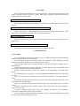
2.2 Nomenclature of parts
2.3 Unpacking and storing
(1) Unpacking
Gently set down the carrying case and make sure its cover is upward. Unlatch and open the case.
Then, take the instrument out of the case.
(2) Storing
Set the telescope close to vertical, and lightly tighten the telescope clamp screw. Align the white
dot, place the instrument into the case with the white dot towards you. Close the case lid and lock the
latch.
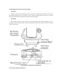
2.4 Battery insertion and recharging
Battery insertion
(1) Press the top button of the battery box, and take off the battery box.
(2) Insert the button of the battery box into the slot on the standard cover, and put the top button
of the battery into the cover until it clicks.
Battery message
Fully recharged new battery can be used 8 to 10 hours continuously. The message "
displays battery consumption. Each segment indicates about three hour's consumption.
"
" and "
"
" indicate that energy is abundant.
" indicates that the battery can be used only about three hours. Recharge the battery or
"
prepare a recharged battery.
"
" flickers then disappears……From start flickering to turning off the power due to lack of
energy, the instrument only can be used several minutes. Stop operating and change the battery as soon
as possible.
Battery recharging
Battery should be recharged with the special charger.
Insert the battery charger into the power source of 110V/220V, remove the on-board battery from
the main body, and connect the plug of the charger to the charging connector on the battery. The
indicating lamp will be turned on, indicating the battery is being recharged and charge will be
completed in 12 hours. Then remove the plug from the charging connector.
Notes on taking off the battery box!
When you take off the battery box, make sure that the power is
turned off, otherwise, the instrument may be damaged.
Note on recharging!
The charger has a built--in circuitry for protection from
overcharging. However, do not leave the charger connected with
power source after charge is completed.
Be sure to recharge the battery at a temperature of 0℃ ~ +45℃.
Recharging may be abnormal beyond the specified temperature
range.
When the indicating lamp, even after connecting the battery and
charger to power source, does not blink, either the battery or the
charger may be damaged.
Notes on storage!
Rechargeable battery can be repeatedly charged 300--500 times.
Complete discharge of the battery may shorten its service life.
For the maximum service life, be sure to charge the battery once a
month.
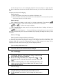
2.5 Mounting and removing of the basal stump
Removing:
Whenever necessary, the instrument can be removed from the tribrach basal stump. First, loosen
the tribrach locking screw by screwdriver. Then, turn the locking button about 180° in counter
clockwise and take off the instrument from the tribrach basal stump.
Mounting:
Put the three fixing feet into the holes of the basal stump and put the directing convex in
accordance with the concave mark. Turn the locking button about 180° clockwise and fix the fixing
screw by screwdriver.
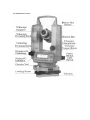
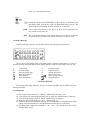
3. KEY PANEL AND DISPLAY MESSAGES
3.1 Keyboard symbols and functions
The keyboard has double functions. The normal function is for angle measurement. When the key
MODE is pressed down, the second function (distance measurement) is executed.
R/L
CONS
Selection key for right or left horizontal angle. Press the key alternately, the
direction of the measured angle changes from right to left.
Special function mode key.
HOLD
The horizontal angle locking key. Press the key twice, the horizontal angle is
locked. Press the key again, the theodolite returns to the former status.
MEAS
Distance measurement key. Press the key to measure distance precisely and
continuously.
Press the key in special mode, the cursor in display board moves to left.
◄
0 SET
Horizontal angle "0" setting key. Press this key twice, the horizontal angle is set
to "0".
TRK
Distance tracking measurement key. Press the key, the distance will be
measured once every second with the precision of 0.01m.
Press the key in special mode, the cursor moves to right.
►
V%
The shift key between vertical and grade percentage. In distance measurement
mode, press the key continuously, slope distance { }, horizontal distance { }
and difference in height { } will be displayed one after another.
▲
Upward / Increase key, press the key in special mode, the cursor moves up /
down or the figure increases.
MODE
▼
The shift key between angle and distance measurement .
Downward / Decrease key. Press the key in special mode, the cursor moves
down / up or the number decreases.
Reticle and display board illuminating key. Press the key to illuminate reticle
and display board. Press the key again, the illuminating lamp turns off. (The
lamp will be off automatically while no operation for 10 seconds.)
PWR
Power switch. Press the key to turn power on; Press the key and hold it over
two seconds to turn power off.
REC
This is an optional function. If the button switch is used. The key will be the
record function key that orders the connected Pocket PC / PDA to record.
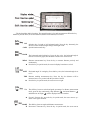
3.2 Display Messages
Liquid crystal display board is used. Normal symbols will be displayed as the follows:
The two lines in the middle of the LCD display angle or distance measurements or a series of
character message. Both right and left sides display symbol or character representing content or unit.
V
H
HR
HL
vertical angle
horizontal angle
horizontal angle right
horizontal angle left
Slope distance
Horizontal distance
%
G
m
ft
grade percentage
angle unit (Gon)
distance unit (meter)
distance unit (foot)
battery energy message
Height difference
4. INITIAL SETTING
The instrument has many functions. EP series electronic theodolite must be initially set before
starting observation.
4.1 Setting items
(1) Unit of angle measurement: 360°、400gon、6400mil (default setting: 360°)
(2) Vertical angle zero point setting: horizontal zero or zenith zero (default setting: zenith zero)
(3) Power auto off function: 30 min or 10 min. (default setting: 10 minutes)
(4) Minimum unit of angle displayed: 1" or 5". (default setting: 1")
(5) Vertical index zero compensation choosing: Auto compensation or uncompensated (default
setting: auto compensation) (For uncompensated instrument, there is no this item.)
(6) Horizontal angle reading passes through 0°、90°、180°、270°, with the beeps or no beeps.
(default setting: beeps)
(2) Press MEAS or TRK key to move the cursor left or right to the figure to be changed.
(3) Press ▲ or ▼ key to change the figure. The figure represents the setting contents in the form
of character codes.
(4) Repeat (2) and (3) for other initial setting items.
(5) When all the initial setting is finished, press CONS key to come back to measurement mode.
When the initial setting is finished, the key CONS must be pressed to confirm and
save the setting.
5. PREPARATION FOR SURVEYING
5.1 Centering and leveling
Setting up the instrument and the tripod
(1) Adjust the tripod legs to obtain a height suitable for observation when the instrument is set
on the tripod.
(2) Hang a plumb bob on the hook of the tripod. And center over the station on the ground
coarsely. At this time, set the tripod and fix the tripod legs firmly into the ground and the
plumb bob coincides with the center of station on the ground.
(3) Adjust the length of each leg to make the tripod head as level as possible. Fix the lock screws
of the tripod legs, then put the instrument on the tripod head and lock with the screws.
Centering and leveling with the optical plummet
(1) Adjust the three leveling screws, position the bubble in the center of the vial. Look through
the optical plummet eyepiece and rotate the eyepiece knob until the reticle can be seen
clearly.
(2) Rotate the focusing knob of the optical plummet until the measurement land mark can be
seen clearly.
(3) Loosen the center screw of the tripod. Look through the optical plummet, and shift the
instrument base on the tripod, taking care to avoid rotating the instrument, until the center
mark of the reticle coincides with the center of station.
(4) By adjusting any two leveling screws, position the bubble in the center of the vial.
(5) Look through the optical plummet, make sure that the land mark coincides with the center of
the reticle. If not, repeat the above steps until they are in coincidence.
(6) Make sure that the land mark coincides with the center of the reticle, then, lock the
instrument.
Caution!
Be sure not to touch the tripod legs,
which may disturb the position of the instrument.
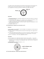
Leveling with plate vial
(1) Let the plate vial in parallel with a line connecting any two of leveling screws. Adjust the two
leveling screws. And position the bubble in the center of the vial by turning the screws in
opposite directions at the same time.
(2) Rotate the plate vial 90° around the vertical axis, make sure that the bubble in the center by
adjusting the third screw.
(3) Repeat (1) and (2), make sure that the bubble is in the center when plate vial is at both
positions.
(4) Rotate the instrument 180° in (1). If the bubble is in the center and always in the center while
the plate vial is moved to any directions, the plate vial is set correctly and the instrument is
leveled.
See the arrows in the above figures for the relation
between the directions of leveling screw's rotation
and the bubbles shifting direction.
If the bubble does not remain in center in (4),
"Adjustment of plate vial" is necessary. Refer to
(8.1) adjustment method.
5.2 Eyepiece adjustment and object sighting
Eyepiece adjustment
(1) Remove the telescope lens cover.
(2) Point the telescope at the sky and rotate the eyepiece ring until the reticle appears at its
maximum sharpness.
When looking into the eyepiece, avoid an intense
look to prevent parallax and eye fatigue. When it is hard
to see the reticle due to poor brightness, press (
to illuminate it.
) key
Object Sighting
(1) Point the telescope at the object using the collimator.
(2) Look through the telescope eyepiece and finely adjust the focusing knob until the object is
perfectly focused.
(3) Use the clamp screw, then the tangent screws to point the object exactly. If focusing is
correct, the reticle will not move in relation to the object, even when you move your eye
slightly left and right.
Turn the focusing knob clockwise to focus a near
object, Turn the knob counterclockwise to focus a
far object.
In (3), parallax may distort the relation between the
object and reticle, resulting in the observation error.
When aligning to an object using the tangent screw,
always align by rotating the screw clockwise. If the
screw is turned past over the object, turn it back to
the original position and sight the object by rotating
the screw clockwise again.
Even when vertical angle measurement is not
required, it is recommended that the object be
placed to the center of the reticle as exact as
possible.
5.3 Turning power ON or OFF
Handle style power switch
Operation
Put the handle up to ON to turn power on. The
display board displays all the mark symbols.
Horizontal angle will be displayed in 2 seconds
and then horizontal angle measurement can be
started.
Put the handle down to off to turn power off.
Display
Key style power switch
Operation
Press PWR key and hold it until all the
symbols are displayed. The power is on.
Horizontal angle will be displayed in 2 seconds
and then the measurement can be started.
Press and hold PWR key over 2 seconds to turn
power off.
Display
When the power is turned on, the displayed angle value is the value saved in
memory last time. If the displayed angle is no use anymore, the horizontal zero
setting can be done.
If no operation is performed for 10 or 30 minutes. The power will be turned off
automatically due to "power auto off function" and the horizontal angle will be
stored in memory automatically.
5.4 Vertical index zero setting
Operation
Turn on the power. Displaying "b" means that
the vertical axis is not vertical. When the
instrument is leveled exactly, "b" will disappear.
If the instrument is leveled exactly before
turning on the power, displaying "V 0 SET" (┌ is
T) means that vertical index is set to zero.
Turn the telescope up and down in normal
position in leveling direction. Vertical index zero
is set when the telescope passes level and the
Display
vertical angle is displayed. The instrument is now
ready for angle measurement.
If vertical index auto compensation set is used, the vertical index can be
compensated. When the vertical index is larger than the designed criterion, "b" will
be displayed. Level the instrument precisely until "b" disappears. Then the
instrument is ready for measurement.
Setting vertical index zero is not necessary for horizontal angle measurement.
Vertical index zero should be set as the suggestion for vertical angle measurement.
The instrument is ready for measurement when a vertical angle value appears.
6 ANGLE MEASUREMENT
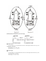
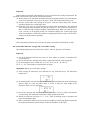
6.1 Normal / reversed position telescope observations
"Normal position telescope" Means that the shaft disc is on the left side of the telescope when
observers face eyepiece lens (see figure). "Reversed position telescope" means that the shaft disc is on
the right side of the telescope when observers face eyepiece lens. Averaging the value of normal /
reversed position can effectively eliminate the instrument systematic errors. So, normal and reversed
observations are made generally.
6.2 Horizontal angle "0" setting (0 SET)
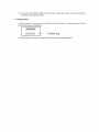
Sight the telescope at object A, press 0 SET twice, set the horizontal angle reading as 0°00'00".
Example:
Aim at object A displaying → HR 50°10'20 → press 0 SET twice → displaying HR 0°00'00"
0 SET key is valid only for horizontal angle.
Horizontal angle can be set to "0" at any time except when HOLD key is locked. If
0 SET is pressed by mistake during operation, nothing will happen unless the key is
pressed again. When the beep stops, the instrument is ready for next step.
6.3 Horizontal and vertical angle measurement (HR. V or HL. V)
(1) Setting the mode for horizontal right and vertical angle (zenith zero) measurement (HR. V).
Turn the instrument clockwise. Aim at the object A exactly, press 0 SET twice to set horizontal
angle to 0°00'00" as the initial zero direction. For example, the steps and displaying contents are as
follows:
Turn the instrument clockwise and aim at object B, suppose that:
(2) Press R / L to change horizontal angle from right to left mode (HL. V).
Turn the instrument counterclockwise (HL), aim at the object A exactly, press 0 SET twice to set
horizontal angle to 0°00'00" as the initial zero direction. The steps and displaying contents are
same as (1) sighting at object A.
Turn the instrument counterclockwise and sight at objects B. For example, the displaying
contents are the followings:
R / L key is invalid for vertical angle.
Press R / L again to change horizontal angle from left mode to right mode (HR. V).
Other directions can be measured continuously after the observation in B direction.
In (1) and (2), only the steps for normal position observation are shown. Reversed
position telescope observation should be made later.
6.4 Horizontal angle lock and release (HOLD)
In the procedure of horizontal angle observation, if you want to retain the measured value, press
HOLD twice. Once horizontal angle is locked, "HRL" flickers at down left of the display and the
horizontal angle value will not change even if you rotate the instrument. When you sight at the needed
direction, press HOLD again to release the lock function. Then the default horizontal angle value of
the direction is the previously locked value.
HOLD is invalid for vertical angle or distance.
If HOLD key is pressed by mistake during operation, it does not matter unless the
key is pressed again. When the beep stops, next operation step can be continued.
6.5 Horizontal angle setting
The instrument has a horizontal angle setting organization, by which, horizontal angle reading
can be set roughly.
(1) Loosen disc clamp screw.
(2) Loosen horizontal clamp screw and fix sighting set by hand.
(3) Turn the rough setting disc, (While, the horizontal reading is changing) until the reading is
roughly the required value.
(4) Tighten disc reading setting clamp screw and horizontal clamp screw.
(5) Set horizontal angle reading exactly the same as the required readings by the horizontal
tangent screw.
(6) Press HOLD key twice to lock the reading.
(7) Turn the instrument and sight at the target exactly. Then, press HOLD key again to release
the lock. So far, the target direction has been set exactly the same as required reading.
While setting initial azimuth, the horizontal angle setting organization is generally
used to preset horizontal angle reading.
6.6 Horizontal angle quadrant setting
(1) Sight at the first object and then press 0 SET twice to set the horizontal angle to zero.
(2) Turn the instrument around the vertical axis until the beep starts, displaying HR 89°59'20".
(3) Lock the instrument by the clamp screw and set the horizontal angle to 90°00'00" by the
tangent screw. Then, fix the quadrant target direction by the telescope reticle.
The theodolite beeps when the reading passes any of 0°, 90°, 180°, 270°. The beep
starts at ±1' range and stops at ±20" range to the respective value.
The beep can be canceled when we do initial setting.
6.7 Vertical angle "0" setting
In initial setting, vertical "0" setting is zenith 0/horizontal 0. (Refer to 4.2 initial setting.)
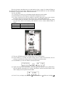
6.8 Measurement of zenith distance and vertical angle
(1) Zenith distance:
If vertical angle is 0° for zenith direction, then the vertical angle measured in this way is the
zenith distance. (See figure)
Zenith distance = (L + 360° - R) /2
Index difference =(L + R - 360°) /2
(2) Vertical angle:
If vertical angle is 0° in horizontal direction, then, the vertical angle measured in this way is the
perpendicular angle. (See figure).
Vertical angle = (L ± 180° - R) /2
Index difference = (L + R -
) /2
If index difference is larger than 10" (i.e. | i | ≥10"), adjustment should be made as
per 8.5 and 8.6 in this manual.
6.9 Grade Percentage
The vertical angle can be converted into grade percentage in angle measurement mode. Press V%,
the display panel shows vertical angle or grade percentage alternately.
grade % = H / D × 100%
The range of grade percentage is from horizon direction to ± 45° (± 50G). Otherwise the
instrument will not display the grade percentage.
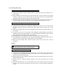
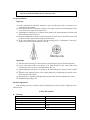
6.10 Stadia Measurement
The distance from the measuring object to the instrument can be obtained by using the stadia hair
of the telescope, with the accuracy of ≤ 0.4% L.
(1) Set up the instrument at point A and put the surveying rod on point B.
(2) Read the intercept (l) of apparent lines above and below the reticle on the survey rod.
(3) The horizontal distance (L) between A and B equals
L = 100 × l
The precision of this kind of distance measurement is not very high. This method is
not used when high precision is required.
7. FORMING A TOTAL STATION ON--LINE WITH EDM
EP series electronic theodolites have two data interfaces: input / output. Five kinds of EDM can
be connected and form a total station. When EP series electronic theodolites are on--line with EDM
and Pocket PC / PDA, it forms a multi--function total station.
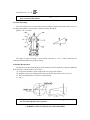
On--line with EDM
(1) Loosen the two fixed screws of theodolite handle and take down the handle.
(2) Mount EDM to the connecting post of theodolite and tighten the screws.
(3) In order to make the two axises in parallel in operation, sight at the target center with the
theodolite aiming axis and sight at the reflector center with the EDM aiming axis.
(4) In normal position, the interface at the inclined downward is the interface connecting EDM.
CE--202 series cable in the following table should be used to connect different kinds of
EDM.
CE--202P
Pentax EDM
CE--202L
Leica EDM
CE--202S
Sokkia EDM
CE--202T
Topcon EDM
(5) The type of EDM should be set in initial setting. (See 4 initial setting)
(6) Press CONS key to confirm the initial setting, return to mode of measurement, turn the
telescope, vertical index zeroing, and enter into angle measurement mode.
(7) Press MODE key to enter into distance measurement mode.
(8) Sight at the target center by theodolite reticle and sight at the reflector center by EDM. Then,
press the distance measuring key to measure the distance and the measured distance value
will be displayed on the panel of the theodolite.
(9) Press V% key to display slope distance ( ), horizontal distance ( ), difference in height ( )
one after another.
Connecting electronic theodolite with Pocket PC / PDA
Connect with Pocket PC / PDA by CE--201 cable to form a multi--function total station with
automatic data collection.
Notes!
The distance between reflector center and target center should be adjusted as the
same as the distance between theodolite transit axis center to EDM transit axis
center.
When calculating horizontal distance, height difference, the vertical angle zero
direction should be set as the instruction of EDM in initial setting.
8. INSPECTION AND ADJUSTMENT
8.1 Plate vial
Inspection
(See 5.1 leveling with plate vial.)
Adjustment
(1) If the bubble of the plate vial moves from the center in (4) of 5.1. Leveling with plate vial,
bring it half way back to the center by adjusting the leveling screw, which is parallel to the
plate vial.
(2) Correcting the remaining half by adjusting the bubble adjusting screws with the adjusting
pin.
(3) Confirm that the bubble does not move from the center when the instrument is rotated by
180°.
(4) Turn the instrument around 90° and adjust the third screw to center the bubble in the vial.
Repeat inspection and adjustment steps until the bubble remains in center in any directions.
8.2 Circular vial
Inspection
No adjustment is necessary if the bubble of the circular vial is in the center after inspection and
adjustment of the plate vial.
Adjustment
If the bubble of the circular vial is not in the center, bring the bubble to the center by using
adjusting pin or adjustable wrench to adjust the bubble adjusting screw. When adjusting, first loosen
the screw on the opposite of the offset side, then, tighten the adjusting screw on the offset side, bring it
to the center. After the bubble stays in the center, keep the fastening strength of the three screws in
uniformity.
8.3 Inclination of reticle
Inspection
(1) Sight at an object A through the telescope and lock the horizontal and vertical clamp screws.
(2) Move point A to the edge of the field of view by the vertical tangent screw (point A').
(3) No adjustment is necessary if point A moves along the vertical line of the reticle.
Adjustment
(1) If the point A does not move along the vertical line, first, remove the eyepiece cover and you
can see the four screws.
(2) Loosen the four reticle adjusting screws uniformly with an adjusting pin. Rotate the reticle
around the aiming axis, and align the vertical line of the reticle with point A'.
(3) Tighten the reticle adjusting screw uniformly. Repeat the inspection and adjustment to check
that if the adjustment is correct.
(4) Install the eyepiece cover.
8.4 Perpendicularity of aiming axis to horizontal axis (2C)
Inspection
(1) Set an object A at a far distance, the same height as the instrument, level and center the
instrument and turn on the power.
(2) Sight at the object A in normal position and read the horizontal angle value. (Suppose that: L
= 10°13'10".)
(3) Loosen vertical and horizontal clamp screws, and reverse the telescope, Sight at the object A
in reversed position and read the horizontal angle value. (Suppose that: R = 190°13'40")
(4) If 2C = L - (R ± 180°) = -30" ≥ ±20", adjustment is needed.
Adjustment
(1) Use the tangent screw to adjust the horizontal read to the correct read R + C = 190°13'25".
(2) Take down the cover of the reticle between eyepiece and focusing screw. Adjust the two
adjusting screws by loosening one and tightening the other. Move the reticle to sight at the
object A exactly.
(3) Repeat inspection and adjustment until | 2C| < 20".
(4) Reinstall the cover of reticle.
8.5 Vertical index difference compensation (optional function)
Inspection
Liquid condenser automatic compensation set is used of vertical index zeroing compensation. We
can check if the function works well by the following method.
(1) Mount and level the instrument and make the telescope parallel with the line connecting the
center of the instrument to any one of the screws. Then, lock the horizontal clamp screw.
(2) Zero the vertical index after turning on the power. Lock the vertical clamp screw and the
instrument displays the vertical angle value.
(3) Rotate the above screw in a direction slowly to about 10mm circumference. The displayed
value changes and then disappears and rises the message "b". The vertical axis incline more
than 3' at this time and exceed the designed compensation range. When you rotate the above
screw reversely to the original position, the instrument displays the vertical angle again
which means that the vertical index difference compensation function works well. (check its
changes at critical position repeatedly.)
Adjustment
If the compensation function does not work well, please contact the local distributor for help.
8.6 Vertical index difference (i angle) and vertical index zeroing
After making adjustments as described in 8.3 and 8.5, make the inspection as following:
Inspection
(1) Set up the instrument and turn the power on. Then, sight at a reference A and obtain the
vertical angle (L).
(2) Reverse the telescope and sight at the object A again and obtain the vertical angle (R).
(3) If vertical angle is zero at zenith, then, I = (L+R - 180°) /2 or (L + R- 540°) /2.
(4) If | i | ≥ 10", vertical index zeroing should be set again.
Adjustment (Setting up vertical index zeroing.)
(1) After leveling the instrument, press and hold V% key until three beeps. The instrument
displays that:
(2) In normal position, turn the telescope around near the horizontal direction until vertical angle
appears. Sight at a clear and stable object A, which is nearly the same height as the
instrument. Press V% key. Displaying:
(3) Reverse the telescope and sight at the object A again. Press V% key to finish vertical index
zeroing setting. The instrument returns back to angle measurement mode.
(4) Repeat the inspection procedure. If | i | ≥ 10", check if anything wrong in operation and
repeat the adjustment again.
(5) If the vertical index difference does not meet the standard yet after being adjusted repeatedly,
the instrument should be repaired. Please contact the distributor for the repair.
The vertical angle displayed in the procedure of zeroing setting is not compensated
and can not be used formally but as a reference value.
8.7 Optical plummet
Inspection
(1) Set the instrument on the tripod, and place a piece of white paper with a cross drawn on it
right under the instrument.
(2) Look through the optical plummet, and move the paper so that the intersecting point of the
cross comes to the center of the field of view.
(3) Adjusting the leveling screws so that the center mark of the optical plummet coincides with
the intersecting point of the cross.
(4) Rotate the instrument around the vertical axis and at every 90° observe that if the center mark
position coincides with the intersecting point of the cross.
(5) If the center mark always coincides with intersecting point, no adjustment is necessary.
Otherwise, the following adjustment is needed.
Adjustment
(1) Take down the protecting cover between the optical plummet eyepiece and focusing knob.
(2) On the white paper with a cross drawn on it, mark the place of the center mark when
instrument moves at every 90°, and mark them A, B, C, D.
(3) Join the diagonals with lines (A, C and B, D), the intersecting point of the two lines is called
0.
(4) Adjust the four adjusting screws of the optical plummet by an adjusting pin, until the center
mark coincides with 0 point.
(5) Repeat the above inspecting and adjusting steps and check that if the adjustment is correct.
(6) Reinstall the protecting cover.
8.8 Other Adjustment
If the leveling screw looses, adjust it with two adjusting pins on the base plate. Tighten the screw
till they are fit.
9. SPECIFICATIONS
Telescope
Image
Magnification
Effective dia. of objective
Resolving power
Field of view
Shortest focusing distance
Erect image
30X
45mm
3"
1°30'
1.4M
Stadia ratio
Stadia constant
Sight distance precision
Tube length
Angle measurement
Angle measurement mode
Dia of circle (vertical, horizontal)
Minimum count
Mode of detection
Measurement Unit
Precision
100
0
≤ 0.40%L
157mm
Photoelectric detection by incremental
encoder
79mm
1" or 5"
Horizontal angle: Dual
Vertical angle: Single
360° /400gon /6400mil optional
EP2002: 2", EP5005: 5"
Leveling vials
Sensitivity of plate vial (/2mm)
Sensitivity of circular vial
30" /2mm
8' /2mm
Vertical compensator (optional function)
System
Working range
Precision
liquid condenser
±3"
1"
Optical plummet
Image
Magnification
Focusing range
Field of view
Erect image
3×
0.5 ~ ∝
5°
Display
Type
LCD, double line, line segment
Data input /output
Data interface (2)
RS--232C
On--board battery
Power source
Voltage
Operating time
Rechargeable Ni-Cd Battery
DC 6V
8 hours
Working environment
Working temperature
-20° ~ +45°
Dimensions and weight
160 × 150 × 330m
5.2kg
Overall dimensions
Instrument weight
The instrument with a plate vial under the battery box has no vertical compensator.
10. APPENDIX
Error messages
Display
E 01
E 02
E 03
E 04
E 05
E 06
b
Meaning and solution
Something wrong with the horizontal disc. Turn the power off. If it
happens again, the instrument should be checked by technician.
Telescope has been rotated too quickly. Turn on the instrument again
and set vertical index zeroing.
The alidade has been rotated too quickly. Press 0 SET key to clear.
If the same thing happens again, the instrument needs to be checked
by technician.
Something wrong with the vertical disc photoelectric transformer,
the instrument needs to be checked by technician.
Something wrong with the horizontal disc photoelectric transformer
(I), the instrument needs to be checked by technician.
Something wrong with the horizontal disc photoelectric transformer
(II), the instrument needs to be checked by technician.
Overpass the compensation range. Level the instrument again.
When error messages appear, check the instrument and your operation steps. When
you confirm that something is wrong with the instrument, contact distributor or
technician for repair.
11. PACKING LIST
Packing case
Electronic Theodolite
Recharge
Plumb bob
Adjusting pin
Soft brush
Awl
Wrench
Woolen cloth
Operation manual CD
Dryer
1
1
1
1
1
1
1
1
1
1
1