1
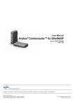
User Manual
Anybus® Communicator™
PROFINET/USS Gateway
Rev. 1.01
HMS Industrial Networks AB
Germany + 49 - 721 - 96472 - 0
Japan
+ 81 - 45 - 478 -5340
Sweden
+ 46 - 35 - 17 29 20
U.S.A
+ 1 - 773 - 404 - 3486
[email protected]
[email protected]
[email protected]
[email protected]
Table of Contents
Table of Contents
Preface
About This Document
How To Use This Document ............................................................................................................ P-1
Important User Information .............................................................................................................. P-1
Related Documents.............................................................................................................................. P-2
Document History ............................................................................................................................... P-2
Conventions & Terminology.............................................................................................................. P-3
Support .................................................................................................................................................. P-3
Chapter 1
Introduction
General Information.............................................................................................................................1-1
Features...................................................................................................................................................1-1
External View ........................................................................................................................................1-2
Status LEDs ...........................................................................................................................................1-3
Chapter 2
Data Exchange
Overview ................................................................................................................................................2-1
USS Master Implementation ...............................................................................................................2-2
General Information...................................................................................................................... 2-2
Configuration................................................................................................................................ 2-2
Operation...................................................................................................................................... 2-2
Slave Data Set ........................................................................................................................................2-3
General Information...................................................................................................................... 2-3
Slave Status Register..................................................................................................................... 2-3
Process Data (PZD)..................................................................................................................... 2-3
Parameter Data (PKW) ............................................................................................................... 2-3
Chapter 3
Network Configuration
General Information.............................................................................................................................3-1
TCP/IP Settings ....................................................................................................................................3-1
SMTP Account Setting.........................................................................................................................3-1
Station Name .........................................................................................................................................3-2
General Information...................................................................................................................... 3-2
SIMATIC Primary Setup Tool ................................................................................................... 3-2
SIMATIC Manager (Edit Ethernet Node) ................................................................................. 3-3
USS & PROFINET Configuration (SIMATIC Manager)..............................................................3-4
General Information...................................................................................................................... 3-4
Step 1: Set Up and Add the Gateway to the Configuration ........................................................... 3-4
Step 2: Specify the Baudrate for the USS Network ....................................................................... 3-5
Step 3: Add Data from the USS Network to the Configuration ................................................... 3-6
Step 4: Downloading the Configuration ......................................................................................... 3-6
Chapter 4
Web Interface
General Information.............................................................................................................................4-1
Administration Pages............................................................................................................................4-2
General Information...................................................................................................................... 4-2
IP Address Settings ...................................................................................................................... 4-2
Master Communication Settings .................................................................................................... 4-3
Master Configuration .................................................................................................................... 4-3
E-Mail Notification Settings......................................................................................................... 4-4
Slave Diagnostics...................................................................................................................................4-5
General......................................................................................................................................... 4-5
Identification and Status ............................................................................................................... 4-5
Slave Status.................................................................................................................................. 4-6
View Process Data of Operational Slaves...................................................................................... 4-6
Appendix A Anybus IPconfig (HICP)
General...................................................................................................................................................A-1
Operation...............................................................................................................................................A-1
Appendix B Connector Pin Assignments
PROFINET Interface (RJ45)............................................................................................................. B-1
Power Connector ................................................................................................................................. B-1
USS Interface (DB9F) ......................................................................................................................... B-1
Appendix C Technical Specification
Mechanical Properties.......................................................................................................................... C-1
Electrical Characteristics ..................................................................................................................... C-1
Environmental Characteristics ........................................................................................................... C-1
Regulatory Compliance ....................................................................................................................... C-2
Preface
About This Document
How To Use This Document
This document contains a general introduction as well as a description of the technical features provided by the Anybus Communicator PROFINET-USS Gateway.
The reader of this document is expected to be familiar with USS and PROFINET network technology,
as well as communication systems in general. The reader is also expected to be familiar with the Microsoft Windows operating system.
Important User Information
The data and illustrations found in this document are not binding. We, HMS Industrial Networks AB,
reserve the right to modify our products in line with our policy of continuous product development. The
information in this document is subject to change without notice and should not be considered as a commitment by HMS Industrial Networks AB. HMS Industrial Networks AB assumes no responsibility for
any errors that may appear in this document.
There are many applications of this product. Those responsible for the use of this device must ensure
that all the necessary steps have been taken to verify that the application meets all performance and safety requirements including any applicable laws, regulations, codes, and standards.
Anybus® is a registered trademark of HMS Industrial Networks AB. All other trademarks are the property of their respective holders.
The examples and illustrations in this document are included solely for illustrative purposes. Because of
the many variables and requirements associated with any particular implementation, HMS cannot assume responsibility or liability for actual use based on these examples and illustrations.
Warning:
This is a class A product. In a domestic environment this product may cause radio interference in which case the user may be required to take adequate measures.
ESD Note:
This product contains ESD (Electrostatic Discharge) sensitive parts that may be damaged
if ESD control procedures are not followed. Static control precautions are required when
handling the product. Failure to observe this may cause damage to the product.
About This Document P-2
Related Documents
Document
-
Author
-
Document History
Summary of Recent Changes (1.00... 1.01)
Change
Removed redundant section ‘Gateway Status Register’
Misc. minor corrections and adjustments
Page(s)
-
Revision List
Revision
1.00
1.01
Date
2006-09-05
2007-08-27
Author
PeP
PeP
Chapter(s)
All
-
Description
Initial revision
Misc. minor corrections
About This Document P-3
Conventions & Terminology
The following terms and conventions are used throughout this document:
•
Numbered lists provide sequential steps
•
Bulleted lists provide information, not procedural steps
•
The terms ‘gateway’ and ‘ABC’ refers to the Anybus Communicator gateway.
•
The term ‘USS’ refers to the Universal Serial Interface networking system.
•
‘PRT’ refers to the PROFINET networking system.
•
‘Slave Data Set’ refers to all data associated with a slave.
•
Hexadecimal values are written in the format 0xNNNN, where NNNN is the hexadecimal value.
Support
HMS Sweden (Head Office)
E-mail:
Phone:
Fax:
Online:
[email protected]
+46 (0) 35 - 17 29 20
+46 (0) 35 - 17 29 09
www.anybus.com
HMS America
E-mail:
Phone:
Toll Free:
Fax:
Online:
[email protected]
+1-773-404-2271
888-8-Anybus
+1-773-404-1797
www.anybus.com
HMS Germany
E-mail:
Phone:
Fax:
Online:
[email protected]
+49-721-96472-0
+49-721-964-7210
www.anybus.com
HMS Japan
E-mail:
Phone:
Fax:
Online:
[email protected]
+81-45-478-5340
+81-45-476-0315
www.anybus.com
Chapter 1
Introduction
General Information
The Anybus Communicator Ethernet-USS Gateway functions as a gateway between the Universal Serial
Interface Protocol (from now on referred to as ‘USS’) and PROFINET IO. Acting as a slave with Real
Time capabilities on the PROFINET side, and as a master on the USS network, it controls up to 31 USS
slaves.
The gateway can be configured solely via the PROFINET configuration tool, i.e. no proprietary configuration utilities are required.
The built-in web server allows monitoration of data through an easy to use web-based user interface.
Additionally, a built-in email client can issue email-messages as the status of the slaves on the USS network changes.
,2&RQWUROOHU3/&
$Q\EXV&RPPXQLFDWRU
0LFURPDVWHU00[[
352),1(7QRGH
352),1(7
9HFWRU&RQWURO
352),1(7QRGH
0RWLRQ&RQWURO
866
5HPRWH$GPLQLVWUDWLRQ
Features
•
PROFINET IO slave, Real Time operation
•
USS master, controls up to 31 USS slaves
•
Up to 16 words of Process Data (PZD) per slave
•
Up to 4 words of Parameter Data (PKW) per slave
•
Configuration via PROFINET
•
Web-based monitoration of data
•
Status notifications via Email
•
DCP (Discovery and Basic Configuration) capable
•
DHCP capable
•
Supports Anybus IPconfig (HICP)
Introduction 1-2
External View
(See also B-1 “Connector Pin Assignments”).
A: PROFINET Interface
See also...
%
- B-1 “PROFINET Interface (RJ45)”
B: Status LEDs
See also...
- 1-3 “Status LEDs”
$
C: Service Port
(reserved)
D: USS Interface
See also...
- B-1 “USS Interface (DB9F)”
&
E: Power Supply Input
See also...
- B-1 “Power Connector”
'
)
- C-1 “Technical Specification”
F: DIN-rail Mechanism
(
The DIN-rail mechanism works as follows:
To snap the gateway on, first press the it downwards (1) to compress the
spring in the DIN-rail mechanism, then push it towards the DIN-rail as
to make it snap on (2)
To snap the gateway off, push the it downwards (1) and pull it out from
the DIN-rail (2), as to make it snap off.
Introduction 1-3
Status LEDs
#
1 - Comm. Status
State
Off
Off
Status
Off line
- No connection with IO Controller
On line, RUN
- Connection to IO Controller established
- IO Controller is in RUN state
On line, STOP
- Connection to IO Controller established
- IO Controller in STOP state
No power or not initialized
Green
Initialized
Green, 1 flash
Diagnostic data available
Green, 2 flashes
Red, 1 flash
Blink. Used by engineering tools for identification.
Configuration Error:
- I/O Size or Configuration Mismatch
No Station Name or invalid TCP/IP configuration
Internal error
Ethernet link established
Transmitting/receiving data on ethernet interface
Ethernet link not established
(no power)
Accessing new configuration
No configuration present
Configuration error
Initialization error
Operational
Configuration in progress
Initialization in progress
Idle (or no power)
Communication detected
Transmitting data
Communication timeout
Green
Green, flashing
2 - Module Status
Red, 3 flashes
Red, 4 flashes
3 - Link/Activity
Off
Green
Green, flashing
4 - (not used)
5 - Gateway Status Off
Red (short period)
Red, flashing (1Hz)
Red, flashing (2Hz)
Red, flashing (4Hz)
Green
Green, flashing (1Hz)
Green, flashing (4Hz)
6 - USS Status
Off
Green
Green, flickering
Red
Chapter 2
Data Exchange
Overview
The mapping of USS data to PROFINET is based on the mapping scheme defined by the PNO working
group for PROFINET IO Proxy Devices. In short, this means that on PROFINET, each USS slave is
represented through a dedicated slot. Slot #0 is reserved for the gateway itself, while slot #1... 31 is associated with the slaves on the USS network. Each slot uses one subslot for the mapping of its assigned
data to PROFINET.
In addition to the Process Data (PZD) and Parameter Data (PKW), the Slave Data Set also features a
Slave Status Register, which reflects the overall status of the slave.
Note that all data is exchanged transparently. This means that in order to be able to access Parameter
Data (PKW), the parameter access protocol used to access PKW data must be implemented entirely on
the PLC side.
8666ODYHV
$Q\EXV&RPPXQLFDWRU*DWHZD\
6ODYH3.:
,2&RQWUROOHU
6ODYH6WDWXV5HJLVWHU
6ORW
6ODYH3.:
6ODYH3='
6ODYH3='
6ODYH6WDWXV5HJLVWHU
,QSXW
2XWSXW
6ODYH6WDWXV5HJLVWHU
UHVHUYHGVHWWR]HUR
6ODYH3.:
6ODYH3.:
6ODYH3='
6ODYH3='
6ODYH3.:
6ODYH3.:
6ODYH3='
6ODYH3='
6ORW
,QSXW
2XWSXW
6ODYH6WDWXV5HJLVWHU
UHVHUYHGVHWWR]HUR
6ODYH3.:
6ODYH3.:
6ODYH3='
6ODYH3='
6ODYH16WDWXV5HJLVWHU
6ODYH13.:
6ODYH13='
6ODYH3.:
8660DVWHU
UHVHUYHG]HUR
6ODYH3='
352),1(7
,QWHUIDFH
6ORW
,QSXW
2XWSXW
6ODYH3.:
6ODYH6WDWXV5HJLVWHU
UHVHUYHGVHWWR]HUR
6ODYH3='
6ODYH3.:
6ODYH3.:
6ODYH3='
6ODYH3='
UHVHUYHG]HUR
6ODYH3.:
6ODYH3='
6ORW1
6ODYH13.:
,QSXW
2XWSXW
UHVHUYHG]HUR
6ODYH16WDWXV5HJLVWHU
UHVHUYHGVHWWR]HUR
6ODYH13.:
6ODYH13.:
6ODYH13.:
6ODYH13='
6ODYH13='
6ODYH13='
6ODYH13='
See also...
•
2-2 “USS Master Implementation”
•
2-3 “Slave Data Set”
•
3-4 “USS & PROFINET Configuration (SIMATIC Manager)”
•
4-1 “Web Interface” (4-3 “Master Configuration”)
Data Exchange 2-2
USS Master Implementation
General Information
The USS protocol (Universal Serial Interface Protocol), defines an access technique according to the
Master-Slave principle for communication via a serial RS-485 based communication bus. The protocol
includes fixed- or variable frame length, cyclic, acyclic and point-to-point communications. The gateway
communicates according to a subset of the protocol, implementing support for cyclic communication
with fixed frame lengths.
All PKW and PZD data is exchanged transparently. This means that the parameter access protocol used
to access PKW data, if required, must be implemented entirely on the PLC side.
Configuration
The gateway can be configured solely using the PROFINET Configuration Tool, e.g. Step 7. No local
configuration tools or settings are required.
See also...
•
3-1 “Network Configuration”
Operation
The gateway will only poll slaves marked as ‘Operational’ in the internal scanlist. Each time a bus cycle
is completed, the gateway checks the status of slaves previously marked as ‘Non-Operational’ and updates the scanlist for the next cycle as necessary.
The status of each individual USS slave can be read in its’ corresponding Slave Status Register.
See also...
•
2-3 “Slave Status Register”
•
4-5 “Slave Diagnostics” (4-5 “Slave Diagnostics”)
Data Exchange 2-3
Slave Data Set
General Information
The data associated with each slave is organized as follows:
Data from Gateway
Slave Status Register
Parameter Data (PKW)
Process Data (PZD)
Data from IO Controller
(reserved, set to zero)
Parameter Data (PKW)
Process Data (PZD)
(2 bytes)
(size is device dependent)
- “ -
Slave Status Register
This register reflects the current status of the slave.
(lsb)
b15
•
b14
b13
RES
b12
b11
b10
b9
FNF USSF
b8
OP
b7
b6
RES CFG
b5
RES
b4
b3
b2
b1
Slave No.
(lsb)
b0
RES (Reserved)
Reserved for future use, mask off and ignore.
•
FNF (Fieldbus Network Fault)
This bit indicates if the fieldbus has gone on- (set) or off- (cleared) line.
•
USSF (USS Fault)
This bit is set if a USS master-slave communication fault has been detected.
•
OP (Operational)
This bit is set if the gateway has detected the slave and found it operational.
•
CFG (Configured)
This bit is set (1) if the node is configured in the master or cleared (0) if not configured.
•
Slave No.
USS slave address (0... 31).
Process Data (PZD)
This is the actual Process Data (PZD) image.
Parameter Data (PKW)
The gateway does not process the Parameter Data (PKW) data in any way. This means that the parameter access protocol used to access PKW data, if required, must be implemented entirely on the PLC
side. Exactly how this is done is beyond the scope of this document.
Chapter 3
Network Configuration
General Information
As mentioned previously, the gateway can be configured solely via the PROFINET configuration tool
(e.g. Step 7). No local configuration utilities or settings are required. The configuration is based on the
PROFINET GSD-file, which can be downloaded from the HMS web site (‘www.anybus.com’).
TCP/IP Settings
To participate on the PROFINET network, the gateway needs a valid TCP/IP configuration. The gateway fully supports the DCP protocol, allowing the IO Controller/Supervisor to change the TCP/IP settings of the gateway during runtime. In addition, the gateway supports DHCP and Anybus IPconfig
(HICP). The TCP/IP settings can also be accessed via the web-based configuration interface.
When using DHCP, the gateway will attempt to retrieve the TCP/IP settings from a DHCP server during startup. If no DHCP server is found, the gateway falls back to its current settings (i.e. any manual
settings that may have been specified earlier).
If no current settings are available (i.e. if the previous settings are invalid), the gateway will halt and indicate an error on the on-board status LEDs. The TCP/IP configuration may however still be accessed
via Anybus IPconfig (HICP).
See also...
•
4-2 “IP Address Settings”
•
A-1 “Anybus IPconfig (HICP)”
SMTP Account Setting
In addition, in order to be able to send notification messages via email, the gateway needs a valid SMTP
server account. These settings can be accessed through the web-based configuration interface.
See also...
•
4-2 “IP Address Settings”
Network Configuration 3-2
Station Name
General Information
When used for the first time, the gateway needs to be assigned a Station Name. This can either be done
using the SIMATIC Manager or using the SIMATIC Primary Setup Tool. Both cases are described in
this document.
SIMATIC Primary Setup Tool
Note: The following example uses the SIMATIC Primary Setup Tool. This tool is sometimes not included in a typical Step 7 installation. In such case, it is also possible to use a built-in function called ‘Edit
Ethernet node’, see 3-3 “SIMATIC Manager (Edit Ethernet Node)”
To specify the Station Name using the Primary Setup Tool, perform the following steps.
1. Open the SIMATIC Primary Setup Tool
2. Select the ‘Network Adapter’-entry in the ‘Settings’-menu
3. Highlight the ethernet interface used for the gateway, and select the ‘Browse’-entry in the ‘Network’-menu.
4. When prompted, enter the station name (e.g. ‘ABC-USS-PRT’)
See also...
•
3-3 “SIMATIC Manager (Edit Ethernet Node)”
Network Configuration 3-3
SIMATIC Manager (Edit Ethernet Node)
Note: The following example uses the SIMATIC Manager. It is also possible to use the SIMATIC Primary Setup Tool, see 3-2 “SIMATIC Primary Setup Tool”
To specify the Station Name using the SIMATIC Manager, perform the following steps.
1. Open the SIMATIC Manager.
2. Select the ‘Edit Ethernet Node...’-entry in the ‘PLC’-menu
3. Select the gateway in the list of devices (‘Browse Network’) and click ‘OK’
4. Specify the Station Name in the ‘Assign device name’-field.
5. When done, click ‘Close’.
See also...
•
3-2 “SIMATIC Primary Setup Tool”
Network Configuration 3-4
USS & PROFINET Configuration (SIMATIC Manager)
General Information
The purpose of this section is to illustrate how to add the gateway and data from the USS slaves to the
PROFINET configuration. Note that a prerequisite for the following examples is that all TCP/IP settings are properly configured.
Step 1: Set Up and Add the Gateway to the Configuration
To configure the gateway, perform the following steps.
1. Open the SIMATIC Manager and start a new project.
2. Select ‘Set PG/PC Interface...’-entry in the ‘Options’-menu.
3. Change the PG/PC Interface to ‘TCP/IP (Auto)’.
4. Highlight the station and double-click on ‘Hardware’.
5. In the ‘HW Config’-window, import the GSD-file by selecting
the ‘Install GSD file...’-entry in the ‘Options’-menu.
6. Drag & Drop the ABC-USS-PRT into the network.
Network Configuration 3-5
Step 2: Specify the Baudrate for the USS Network
To specify the baudrate for the USS communication, perform the following steps:
1. Highlight the gateway in the network configuration (‘HW Config’-window, ‘A’)
2. Right-click on slot #0 (‘B’) and select ‘Object Properties’.
$
%
3. Select the ‘Parameter’-tab (‘C’)
4. Specify the baudrate for the USS network (‘D’)
&
'
(
5. Click ‘OK’ when done (‘E’)
Network Configuration 3-6
Step 3: Add Data from the USS Network to the Configuration
Each slave on the USS network is represented trough a dedicated slot. The slot number correlates 1:1
to the USS slave number, i.e. slot #23 on PROFINET represents USS slave #23.
To add data from the USS network to the configuration, perform the following steps:
1. Right-click on a slot corresponding to the USS slave for which
data shall be added.
2. Select the ‘Insert Object...’-entry.
3. Select an object which matches the data sizes (PKW and PZD)
of the slave which shall be added.
4. Repeat steps 1... 3 for all USS slaves which shall be included in
the configuration.
Example:
Example with a single USS slave with the following properties:
- Slave address #1
- 4 words of Parameter Data (PKW)
- 16 words of Process Data (PZD)
Note: The ranges shown in the ‘I Address’- and ‘Q address’columns includes space for the Slave Status Register in both
directions.
Step 4: Downloading the Configuration
To download the finished configuration to the IO Controller, select
the ‘Download...’-entry in the ‘PLC’-menu.
Chapter 4
Web Interface
General Information
The gateway features a web-based configuration and monitoration interface, used to set up basic communication properties (i.e. IP address, network mask etc.) as well as to monitor the status and data of
the individual slaves on the USS network.
To access the web-based configuration interface, perform the following steps:
1. Open a web browser (e.g. Mozilla Firefox)
2. Enter the IP address of the gateway in the address field. The gateway will ask for authentication.
The username is ‘USS Gateway’, and the password is ‘1234’.
The main page contains links to the following sub-pages:
•
Administration
See also...
- 4-2 “Administration Pages”
•
Slave Diagnostics
See also...
- 4-5 “Slave Diagnostics”
•
User defined pages (Expert Users Only)
Optionally, advanced users may create custom web pages. Contact HMS for further information.
Note: Certain features requires a JAVA-capable browser.
Web Interface 4-2
Administration Pages
General Information
The main administration page features the following sub-pages:
•
IP address settings
See also...
- 4-2 “IP Address Settings”
•
Master Communication Settings
See also...
- 4-3 “Master Communication Settings”
•
Master Configuration
See also...
- 4-3 “Master Configuration”
•
E-Mail Notification Settings
See also...
- 4-4 “E-Mail Notification Settings”
IP Address Settings
This page provides access to basic network settings, i.e. IP address, subnet mask etc.
By default, the gateway retrieves these settings
from a DHCP server. If using manually specified
settings, make sure to uncheck the ‘DHCP enabled’-checkbox.
See also...
•
3-1 “TCP/IP Settings”
Note: Generally, any changes made to the settings
on this page requires a reset to have effect.
Web Interface 4-3
Master Communication Settings
This page presents the communication settings for the USS interface.
•
Baudrate
The following baudrates are supported:
- 9600bps
- 19200bps
- 38400bps
(Note that the baudrate is specified in the
PROFINET configuration tool, see 3-5
“Step 2: Specify the Baudrate for the USS
Network”)
•
Data bits
(fixed to 8)
•
Start bits
(fixed to 1)
•
Stop bits
(fixed to 1)
•
Parity
(fixed to even)
Master Configuration
This page presents an overview of the communication with the slaves on the USS network.
The leftmost column contains the USS device
address, followed by the data sizes (specified in
words) for that device.
The remaining columns reflects how the data is
mapped internally in the gateway.
Web Interface 4-4
E-Mail Notification Settings
The gateway continuously monitors the status of OP, USSF and FNF in the Slave Status Registers. Optionally, an email notification can be issued when the status of a slave changes.
•
Recipient
Destination address.
•
Sender
Address of the sender.
•
Subject
Subject for the message.
•
Message
Actual message body.
Optionally, additional keywords can be included in the message as follows:
Keyword
<Slave>
<Status>
•
Action
Includes the number of the slave
Includes the status of the slave
Email Notification Setup
Specifies which slaves that shall trigger email status notifications; to enable notification for a particular slave, check the corresponding checkbox. To disable notification for a slave, uncheck the
checkbox.
Click ‘Store’ to save any changes.
Example:
Recipient:
Sender:
Subject:
Message:
‘[email protected]’
‘[email protected]’
‘Oops’
‘Slave no. <Slave> has changed status to <Status>’
Note: This features requires a valid SMTP server account. The SMTP account settings can be accessed
via the built-in web server.
See also...
•
4-2 “IP Address Settings”
Web Interface 4-5
Slave Diagnostics
General
The main diagnostic page features the following sub-pages:
•
Identification and Status
See also...
- 4-5 “Identification and Status”
•
Slave Status
See also...
- 4-6 “Slave Status”
•
View Process Data of Operational Slaves
See also...
- 4-6 “View Process Data of Operational Slaves”
Identification and Status
This page displays information about the gateway as well as the general status of the USS network (this
information may be useful when contacting HMS support services).
•
Gateway Name
(‘Profinet Gateway for Siemens Drives with USS Protocol ’).
•
Gateway Version
(General gateway firmware revision).
•
Anybus Type
(Higher level network interface type).
•
Anybus Version
(Fieldbus interface firmware revision).
•
Gateway Status
(Overall gateway status).
•
USS Master Status
(Status of USS master).
•
PROFINET Interface
(Fieldbus interface status).
Web Interface 4-6
Slave Status
This page shows status information for each slave device on the USS network.
•
Dev
Device address.
•
Operational
Device status (e.g. ‘Operational’, ‘Non-Operational’, ‘Not Present’ etc.).
•
PKW Size
Size (in words) of Parameter Data (PKW) associated with the slave device.
•
PZD Size
Size (in words) of Process Data (PZD) associated with the slave device.
View Process Data of Operational Slaves
This page can be used to monitor the Process Data
(PZD) of all operational slaves on the USS network.
All data is represented as an array of words in hexadecimal format.
Appendix A
Anybus IPconfig (HICP)
General
The gateway supports the HICP protocol used by the Anybus IPconfig utility, which can be downloaded
free of charge from the HMS web site. This utility may be used to access the TCP/IP settings of any
Anybus product connected to the network via UDP port 3250.
Operation
Upon starting the program, the network is scanned for Anybus products. The network can be rescanned
at any time by clicking ‘Scan’.
In the list of detected devices, the gateway will by default appear as ‘ABC-PRT-USS’.
To alter the network settings of the gateway, doubleclick on its entry in the list. A window will appear,
containing the actual IP settings.
Validate any changes by clicking ‘Set’, or click ‘Cancel’
to cancel.
Optionally, the configuration can be protected from
unauthorized access by a password. To enter a password, click on the ‘Change password’ checkbox, and
enter the password under ‘New password’.
See also...
•
3-1 “TCP/IP Settings”
•
4-2 “IP Address Settings”
Appendix B
Connector Pin Assignments
PROFINET Interface (RJ45)
Pin
1
2
3
4
5
6
7
8
Signal
TD+
TDRD+
RD-
Notes
Normally left unused; to ensure signal integrity, these pins are tied
together and terminated to PE via a filter circuit.
Normally left unused; to ensure signal integrity, these pins are tied
together and terminated to PE via a filter circuit.
Power Connector
Pin
1
2
Signal
+24VDC
GND
Notes
-
Notes:
•
•
Use good quality 60/75 or 75×C copper (CU) wire only.
Terminal tightening torque must be between 5... 7 lbs-in (0.5... 0.8 Nm)
USS Interface (DB9F)
Pin
1
2
3
4
5
6
7
8
8
Signal
+5V Output
Signal Ground
RS485 +
RS485 -
Notes
100mA max.
(do not connect)
IHPDOH IMPORTANT: This pin should only be connected to the Signal
Ground of other nodes (if available). It must not be connected to Protective Earth (PE), since doing so may cause serious damage to the
serial transceivers in the gateway.
(do not connect)
-
Appendix C
Technical Specification
Mechanical Properties
Housing
Plastic housing with snap-on connection to DIN-rail, protection class IP20
Dimensions
120 mm x 75 mm x 27 mm, L x W x H (inches: 4,72” x 2,95” x 1,06”; L x W x H)
Electrical Characteristics
Power Supply
Power: 24V ± 10%
Power Consumption
Maximum power consumption is 280mA. Typically around 100 mA
Environmental Characteristics
Relative Humidity
The product is designed for a relative humidity of 0 to 95% non-condensing
Temperature
Operating:
Non Operating:
±0°C to +55°C
-25°C to +85°C
Technical Specification C-2
Regulatory Compliance
EMC Compliance (CE)
This product is in accordance with the EMC directive 89/336/EEC, with amendments 92/31/EEC and
93/68/EEC through conformance with the following standards:
•
EN 50082-2 (1993)
EN 55011 (1990)
•
Class A
EN 61000-6-2 (1999)
EN 61000-4-3 (1996) 10V/m
EN 61000-4-6 (1996) 10V/m (all ports)
EN 61000-4-2 (1995) ±8kV
±4kV
Air Discharge
Contact discharge
EN 61000-4-4 (1995) ±2kV
±1kV
Power port
Other ports
EN 61000.4.5 (1995)
±0.5kV Power ports (DM/CM)
±1kV Signal ports
UL/c-UL compliance
The certification has been documented by UL in file E214107.