1
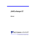
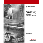
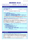
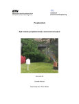
Teleoperated Control of Hydraulic Equipment for Hazardous Material Handling by Michael Ryals Fleming Thesis submitted to the Faculty of the Virginia Polytechnic Institute and State University in partial fulfillment of the requirement for the degree of MASTERS OF SCIENCE IN MECHANICAL ENGINEERING Dr. Charles F. Reinholtz, Chairman Dept. of Mechanical Engineering Dr. Alfred L. Wicks Dept. of Mechanical Engineering Dr. Harry H. Robertshaw Dept. of Mechanical Engineering December 4, 2003 Blacksburg, VA Keywords: Teleoperate, Remote Control, Hazardous Material, Excavator, Hydraulics, LabVIEW Teleoperated Control of Hydraulic Equipment for Hazardous Material Handling Michael Ryals Fleming Abstract Traditionally, teleoperation has been an expensive and lengthy process. This thesis shows that by incorporating off-the-shelf technology into a modular design, teleoperation can be developed rapidly and inexpensively. Within six months and a hardware cost of $20k, a group of Virginia Tech students and faculty converted a Case CX-160 excavator to teleoperated control. With full wireless functionality of the excavator’s six degrees-offreedom, ignition, and remote cameras at 3000 ft., the teleoperated design meets or exceeds customer demands. For over a year, the teleoperated excavator has demonstrated effectiveness, robustness, and durability in multiple unexploded ordnance (UXO) site remediation projects. Acknowledgements Being part of this project has been one of the most challenging and rewarding opportunities I have had at Virginia Tech. The completion and success of this project would not have been possible without the contributions of each team member and support from the Virginia Tech Mechanical Engineering department. I would like to start by thanking Dr. Charles Reinholtz for serving as my committee chairman and advisor. His devotion to the students is evident by the constant student line outside his office. With his many accomplishments, the respect and time he demonstrates towards his students is admirable. It has been a pleasure working with you. This project would not have been possible without the relationship between Dr. Al Wicks and NSWC-DD. From managing the project to turning wrenches, he has continuously demonstrated his commitment to the project’s success without ever taking credit. While I am still not fond of the 5:00 AM trips, I will miss the trips to Shoney’s and Sheetz. I would like to thank Dr. Harry Robertshaw for serving on my committee. His spearheading efforts to bring hands-on learning into the ME Lab classes provided me with a foundation in DAQ and LabVIEW that were instrumental to the success of this project. I would like to particularly thank Chris Terwelp and Ian Hovey for their countless hours implementing the hydraulic and electrical systems. The project’s success is evident in their attention to detail and drive for success. I especially appreciate their assistance in enduring the painstaking task of optimizing software settings during those late nights. I would like to thank George Clotfelter for his support even after I erased the excavator ECU. I also appreciate you putting me up for a night when the software upgrade didn’t go as smooth as I claimed. I would also like to thank the National Instruments support of Brian MacCleery and Eric Dean for their technical expertise that I heavily relied upon. Most importantly, I would like to thank my non-technical family who has had to deal with my engineering mishaps over the years. You have always supported me even when I took out all the televisions by transmitting 1 kW over the airwaves. iii This page left intentionally blank iv Table of Contents Chapter 1 – Introduction…………………………………………………………….. 1 1.1 Project Overview……………………………………………………………….. 1 1.2 Technical Challenges…………………………………………………………… 2 Chapter 2 – Literature Review………………………………………………………. 4 2.1 Teleoperated Ground Vehicles…………………………………………………. 4 2.2 Control Methods………………………………………………………………... 8 Chapter 3 – Overall Design…………………………………………………………... 10 3.1 Computation and Telemetry……………………………………………………..10 3.2 Remote Station………………………………………………………………….. 14 3.3 Teleoperated Machine…………………………………………………………... 17 Chapter 4 – Software Development…………………………………………………..22 4.1 LabVIEW……………………………………………………………………..… 22 4.2 Real-Time Engine………………………………………………………………. 25 4.3 Web Server………………………………………………………………………25 Chapter 5 – Communication Protocol……………………………………………..... 27 5.1 Teleoperated Controls and Feedback…………………………………………… 27 5.2 Communication Structure………………………………………………………. 28 5.3 Telegram Format………………………………………………………………... 30 Chapter 6 – Message Compilation……………………………………………………32 6.1 Synchronization Messages……………………………………………………… 32 6.2 Hydraulic Control Message…………………………………………………...... 34 6.3 Switch Control Message………………………………………………………... 39 6.4 Machine Feedback Message……………………………………………………. 40 6.5 Update Settings Message……………………………………………………...... 41 Chapter 7 – Conclusion……………………………………………………………..... 44 References……………………………………………………………………………... 46 Vita…………………………………………………………………………………….. 48 v This page left intentionally blank vi List of Tables 5.1 6.1 6.2 6.3 6.4 6.5 6.6 6.7 Telegram format……………………………………………………………….. 30 Remote Station Synchronization Message…………………………………….. 33 Machine Synchronization Message……………………………………............. 33 Machine Synchronization Confirmation Message……………………………... 33 Hydraulic Control Message……………………………………………............. 37 Switch Control Message……………………………………………………….. 40 Machine Feedback Message…………………………………………………… 41 Machine Settings Message……………………………………………………... 43 vii List of Figures 1.1 2.1 2.2 2.3 2.4 2.5 3.1 3.2 3.3 3.4 3.5 3.6 3.7 3.8 3.9 3.10 3.11 3.12 3.13 4.1 4.2 4.3 4.4 5.1 5.2 5.3 6.1 6.2 6.3 7.1 Case CX-160 and team members………………………………………………. 2 Vehicle teleoperation……………………………………………………........... 4 Teleoperated dune buggy [4]…………………………………………………... 5 ORILLC Standard Teleoperation System (STS) [5]………………….………... 6 Omnitech teleoperated systems [6]……………………………………….......... 7 Robotec teleoperated systems [7]……………………………………………… 8 Teleoperated CX-160 excavator……………………………………………….. 10 National Instruments FieldPoint FP-2000 controller [13]……………………... 11 FieldPoint distributed I/O system [13]…………………………………............. 12 Data-Linc SRM-6000 wireless serial modem [14]…………………………….. 13 Futaba Industrial Radio Control VSD-2002 [15]……………………………….13 Remote station…………………………………………………………............. 14 Remote station hardware flow diagram………………………………………... 15 Operator console……………………………………………………………….. 16 Operator graphical user interface………………………………………............. 17 Case CX-160 degrees of freedom……………………………………………… 18 Teleoperated machine hardware flow diagram………………………………… 19 Remote cameras on teleoperated CX-160……………………………………… 20 Teleoperated machine software interface……………………………………… 21 Front panel of Function Waveform Generation.vi……………………………... 23 Block diagram of Function Waveform Generation.vi…………………………. 24 Real-time LabVIEW deployment hardware…………………………………… 25 The Function Waveform Generation.vi Web server interface…………............. 26 Required control and feedback data for teleoperated control………………….. 28 Communication protocol for teleoperated CX-160……………………............. 29 Block diagram of CRC.vi………………………………………………............. 31 Synchronization flow diagram…………………………………………............. 34 Joystick and pedal control voltage scaling with dead-band in LabVIEW……... 36 Proportional valve reference voltage calculation in LabVIEW………………... 38 Teleoperated CX-160 excavator in operation………………………...………... 44 ix Chapter 1 - Introduction The purpose of this document is to explore cost effective methods for converting manually operated hydraulic equipment to teleoperated control. Traditionally, teleoperation has been an expensive and lengthy task [1]. This document presents methods of using off-the-shelf technology to retrofit a Case CX-160 hydraulic excavator to teleoperated control. The design presented in this thesis demonstrates that teleoperated hydraulic equipment can be developed rapidly and inexpensively. The teleoperated CX-160 was developed for the Naval Surface Warfare Center in Dahlgren, VA to excavate buried unexploded ordnance (UXO). While this design is focused on UXO excavation, it is applicable in other hazardous material handling applications. In addition, the developed teleoperated system provides a foundation for future work such as coordinated control and automation. 1.1 Project Overview In February 2002, the Naval Surface Warfare Center in Dahlgren, VA (NSWC-DD) and the Mechanical Engineering department at Virginia Tech embarked on a project to develop a teleoperated system capable of unearthing buried unexploded ordnance (UXO). With a delivery time of six months, it was decided to retrofit an excavator to teleoperation. Considering the large area to be excavated and the potential for finding heavy buried UXO, a 16-ton Case CX-160 excavator was selected for the task. NSWC-DD mandated four specific requirements for the teleoperated CX-160. It had to be capable of: (1) operating at a maximum distance of 3000 ft; (2) converting from manual to remote operation in less then three minutes; (3) providing safe and efficient operation, and (4) being delivered within six months. Figure 1.1 shows the excavator along with the team of Virginia Tech faculty and students, NSWC-DD engineers, and Case personnel assembled to tackle this task. 1 Figure 1.1: Case CX-160 and team members 1.2 Technical Challenges Converting a 16-ton hydraulic excavator to teleoperated control presents a variety of technical challenges. Design decisions associated with by-wire hydraulic control, software development, telemetry, operator feedback, system durability, and safety significantly impact project success. Improper modification of high pressure hydraulic systems may result in human injury and machine damage. Therefore, safety is a high priority when working with hydraulic components. The proper selection and placement of hydraulic components is critical to optimal by-wire control. Consequently, hydraulic system flow rates, pressures, and system response require close attention [2]. Robustness and optimization in software design are essential to reliable real-time control. Software development must resolve errors and failures while still maintaining stability and functionality. Control data must be sampled, packaged, transmitted, deciphered, and executed efficiently, frequently, and with minimal delay. Computational and control hardware should be capable of executing developed software and expanding for future software development. The telemetry solution must be capable of supporting system bandwidth and be resistant to interference. The operator must have an understanding of the work environment in order to make control decisions. Thus, sensors need to be placed on the vehicle or at the work 2 site. Sensor information must then be relayed to the operator and displayed in a useful fashion. Sensor selection, placement, and display are critical to the operator’s understanding of the work environment and task efficiency. All hardware components onboard the teleoperated machine must be resistant to heat and cold, weather, vibration, and other elements associated with machine operation and its work environment. Therefore, it is important that durable hardware is selected and appropriate measures are taken to protect the equipment from damage. Due to the dangerous UXO work environment, safety features should be implemented in the teleoperated design to isolate system failures. Safety systems should be reliable, independent, and tested to ensure functionality at all times. 3 Chapter 2 – Literature Review For this thesis, vehicle teleoperation will be defined as operating a vehicle at a distance (see figure 2.1). Furthermore, the spectrum of teleoperated control will encompass direct, coordinated, and supervisory control. Control is always necessary, but circumstances often warrant teleoperation. Teleoperation is often implemented in difficult-to-reach environments, to improve task efficiency, and to reduce human risk [3]. Human Operator Barrier Telerobot Local Loop Sensor Feedback Information Remote Loop Level of operator Control Figure 2.1: Vehicle teleoperation. An operator at a control station generates commands and receives feedback from remote sensors. The vehicle executes the operator commands. Vehicle teleoperation differs from remote control operations (i.e., line-of-sight operation) in several aspects. Since teleoperated vehicles are often deployed in unknown, unstructured, and dangerous environments, potential system losses make robust operation imperative. And since task performance is directly correlated to system control, vehicle teleoperation requires efficient motion command generation. Also, vehicle teleoperation requires localized sensor data which can then be relayed to the operator for decision making. 2.1 Teleoperated Ground Vehicles Vehicle teleoperation first appeared in the early 1900’s, but it was not until the 1970’s that systems became widely used. Today, vehicle teleoperation is in air, space, ground, and underwater applications. Since teleoperation development occurred over different periods and in different environments, vehicle teleoperation is referred to by numerous terms including: ROV (Remotely Operated Vehicles), RPV (Remotely Piloted Vehicles), UAV (Unmanned Air Vehicles), and UGV (Unmanned Ground Vehicles). The first two 4 abbreviations clearly refer to teleoperated systems, while the last two encompass both teleoperated systems and autonomous systems. Because there are such a variety of teleoperated systems, the following section will outline several teleoperated ground vehicle systems for use in military and industrial applications. The components and features of the SPARWAR Advanced Teleoperated Technology (ATT), Omnitech Standard Teleoperation System (STS), and Robotec Operating Platform for Unmanned Vehicles Systems (OPUS) are summarized below. Space and Naval Warfare Systems Command (SPAWAR): In 1982, the Advanced Teleoperator Technology (ATT) Teleoperated Dune Buggy was developed to focus on teleoperator control methodology. It demonstrated that remotely operated ground vehicles could be driven in “complex natural terrain”. This technology incorporated stereo head-couple visual displays, binaural audio feedback, and controls similar to those on the vehicle. Particularly, the ATT effort demonstrated the efficiency of stereo head-coupled visual display systems, binaural audio feedback, and isomorphic vehicle controls for high-speed remote vehicle operations [4]. Figure 2.2: Teleoperated dune buggy [4]. Omnitech: In cooperation with the Joint Robotics Program (JRP), Omnitech Robotics International, LLC (ORILLC) developed several systems for converting ground vehicles to remote control and teleoperated control. One such system is the Standard 5 Teleoperation System (STS). The STS kit consists of modular components for converting a variety of vehicles to remote control and teleoperated control. As shown in figure 2.3, the STS system includes: (1) Operator Control Unit; (2) Vehicle Control Unit; (3) High Integration Actuators; (4) Safety Radio Transmitter; (5) System Input/Output; and (6) Video Transmitter Unit [5]. 1 6 4 3 5 2 Figure 2.3: ORILLC Standard Teleoperation System (STS). (1) Operator Control Unit; (2) Vehicle Control Unit; (3) High Integration Actuators; (4) Safety Radio Transmitter; (5) System Input/Output; (6) Video Transmitter Unit [6]. The Operator Control Unit (OCU) provides the operator with remote vehicular control. The OCU includes a radio transceiver, operator controls, video display, and an instrument panel. The Vehicle Control Unit (VCU) is a modular device that controls the central control computer and all control interfaces for the STS vehicle. The VCU uses a serial control bus and CAN interface to communicate with all the peripheral control components. The High Integration Actuators (HIA) govern the vehicle operator controls such as throttle, braking, and steering. The HIA interfaces with motor potentiometer feedback, optical encoder, load cell, temperature sensors, servo power amplifiers, and CAN interfaces. With different interfaces, the HIA can be fitted with an array of control components, allowing it to be adapted to a variety of vehicles. Nearly 60 vehicles are equipped with STS kits for unmanned operation, including tanks, tractors, High Mobility Multipurpose Wheeled Vehicles (HMMWV), Skytrak forklift, all-terrain vehicles (ATVs), and trucks (see figure 2.4). These remote control and teleoperated control 6 vehicles are being used in applications such as construction, mining, counterterrorism, explosive ordnance handling/disposal, fire fighting, and hazardous material handling [6]. (b) (a) Figure 2.4: Omnitech teleoperated systems. (a) teleoperated John Deer T3 tractor; (b) High Mobility Multipurpose Wheeled Vehicle (HMMWV) [6]. Robotec: Since 1992, Robotec has provided remote control and teleoperated systems for the military, industry, and research applications. The HazHandler product was developed to convert Bobcat machinery into remote control and teleoperated control. As shown in figure 2.5, Robotec has developed custom control systems termed the Operating Platform for Unmanned Systems (OPUS) and Vehicle Network for Unmanned Systems (VeNUS). These systems are embedded micro-controller based systems using off the shelf components. Some of the HazHandler features include: emergency shutdown controls on the remote console and on all sides of the vehicle; a joystick “deadman” feature which places the vehicle in standby mode when the joystick handle is not pressed; and communication and command verification before vehicle movement. Upon a communication failure, the system shuts down into failsafe mode. OPUS is currently in use on loaders in steel mills and carrying land mine detection equipment [7]. 7 (a) (b) Figure 2.5: Robotec teleoperated systems. (a) Vehicle Network for Unmanned Systems (VeNUS); (b) Robotech Industries HazHandler [7]. 2.3 Control Methods Control methods for teleoperated systems can be divided into three generic categories: direct, coordinated, and supervisory control. Direct control is the “traditional” control systems based on hand-controllers and video feedback. Coordinated control builds upon direct control by incorporating a control loop in the teleoperated vehicle. Supervisory control includes a system in which an operator oversees a lower level of intelligence by monitoring and reprogramming system routines. Direct Control: The most common method for teleoperation control is through direct control. Traditionally, hand-controllers are used to control the system while monitoring video feedback from cameras mounted on the teleoperated system. In direct control, the remote operator is controlling the system in the same way as an on-board operator would. Direct control techniques are appropriate when real-time human decision-making and control is required and when the environment can support highbandwidth, low delay communications [8]. By nature, direct control methods have a level of control delay. This delay may be negligible or significant, depending upon the flight time of the radio transmission and computer processing. Significant delays are typical in direct control of space vehicles. Coming from the Earth surface, direct control of vehicles in low Earth orbit results in a 8 round trip delay (the time from sending a signal until the receipt of feedback pertaining to the signal) of 0.4 seconds. For vehicles on or near the moon, these delays are typically 3 seconds. Early experiments with time delay in direct control applications used a moveand-wait strategy. In this strategy, the operator commands a small incremental motion, waits for the feedback, and then commands another small motion. With such small control movements, the time to complete task can be long. As a result, continuous direct control of space vehicle systems has been discouraged [9]. Predictor displays present a computer-derived estimate of the teleoperated vehicle future state. This estimate can then be displayed to the operator for decision making. Predictor displays are useful in applications with significant transmission delays and slow on-board camera frame rates. Predicator displays have been successfully demonstrated on gun sights, ships and submarines, and as head-up optical landing aids for aircraft pilots [10]. Coordinated Control: Coordinated control expands on direct control by adding a level of internal control at the teleoperated vehicle. As with direct control, the operator transmits a control signal to the teleoperated machine. The teleoperated machine then executes this control within an onboard control loop. Coordinated control is used to close control loops that the operator is unable to control due to delay. However, coordinate control does not include any level of autonomy at the controlled machine. Supervisory Control: Over forty years ago, Sheridan coined the term, “supervisory control,” for a control exercised by an intelligent controller under human supervision [11]. In supervisory control systems, the operator compiles a set of tasks for machine execution. Throughout execution, the operator reprograms and monitors intermittent feedback to ensure safe and proper operation. Such standalone operation requires some level of machine intelligence. At any point, the human operator has the option to take on a greater level of control for either routine or emergency situations. The principal advantages of supervisory control over direct-control are: (1) quicker task completion time; (2) quicker response time to unexpected events; (3) greater control accuracy; (4) the ability to perform long-duration tasks without continuous human attention [12]. 9 Chapter 3 – Overall Design After reviewing the design requirements and surveying the existing commercial solutions, the design team decided to develop a new teleoperated excavator. The new system, which is described in this thesis, meets or exceeds all customer specifications previously described. A modular hardware design using off-the-shelf technology was adopted to expedite development, simplify debugging, and allow for future expansion. In addition, this design can be replicated for use on similar hydraulic machinery. The CX160 excavator shown in figure 3.1 was converted to teleoperation within six months at a hardware cost of less then $20k. This chapter provides an overview of the hardware design for converting a Case CX-160 excavator to teleoperated control. Figure 3.1: Teleoperated CX-160 excavator 3.1 Computation and Telemetry This section provides an overview of the computational and telemetry off-the-shelf components used in the hardware design of the teleoperated excavator. Based on the standalone operation, compact size, and industrial-grade reliability, the National 10 Instruments FieldPoint (FP) product line was chosen to execute developed LabVIEW software for the control of the CX-160 teleoperated excavator. With a 115.2 kbps throughput, the Data-Linc SRM-6000 wireless serial modem was implemented to transmit data between the FieldPoint systems at the remote station and teleoperated machine. The Futaba VSD-2000 emergency stop system was selected as a redundant failsafe system. FieldPoint: The National Instruments FP-2000 controller was chosen for standalone software execution at the remote station and the teleoperated machine. The FieldPoint controllers contain a real-time LabVIEW embedded controller for intelligent control of up to nine FieldPoint I/O (input/output) modules. FieldPoint controllers connect directly to Ethernet and auto-negotiate on the network for 10 Mb/s or 100 Mb/s communication rates. The Ethernet port serves as a high-speed link for downloading application code, performing real-time software debugging, and exchanging information with other networked computers. Such connectivity is built on a TCP/IP network protocol and incorporates publisher/subscriber networking. The FP-2000 controller also contains a RS-232 port for serial communication [13]. Figure 3.2: National Instruments FieldPoint FP-2000 controller [13] A variety of I/O modules can be connected to the FieldPoint controllers, including analog, discrete, counter, and dual-channel modules. These modules slide into terminal bases and can be linked from a FieldPoint controller module as shown in figure 3.3. The controller module can then execute the functions of each I/O module through developed LabVIEW software. In this project, analog input (FP-AI-100), analog output (FP-AO210), digital input (FP-DI-300), and relay (FP-RLY-420) modules are used. 11 Figure 3.3: FieldPoint distributed I/O system [13] During testing, it was noticed that these modules occasionally failed to connect properly. This failure was caused by poor terminal block connector design. The latest National Instruments compact FieldPoint (cFP) product line has resolved this issue by using a 4-port or 8-port backplane for controller and module connectivity. While the compact FieldPoint product line was available during project development, it is suggested that future use of this design incorporate the compact FieldPoint components. SRM-6000 Serial Radio Modems: The Data-Linc SRM-6000 wireless serial modems were chosen to relay data between the FieldPoint systems at the remote station and teleoperated machine. With serial connectivity, the radio modems and FieldPoint controllers connect and exchange data through RS-232 ports. The Data-Linc wireless radio modems provide a 115.2 kbps data throughput up to 25 miles line-of-sight using omni directional antennas (assuming 75% frequency availability). The SRM-6000 employs frequency hopping spread spectrum (FHSS) technology in the 900 MHz ISM (industrial/scientific/medical) band. A 32-bit Cycle Redundancy Check (CRC) error correction is used to verify transmitted packet integrity. If a corrupt packet is received, a retransmission of that packet is requested [14]. The radio modem CRC feature was disabled for this project. Instead, error correction is implemented in the communication protocol as outlined in section 5.3. 12 Figure 3.4: Data-Linc SRM-6000 wireless serial modem [14] The SRM-6000 provides external lights indicating when another SRM-6000 radio modem is detected and when data is being exchanged. However, there are no provisions for the transmission of link status and signal quality (i.e., Signal to Noise Ratio). If this information were made available, developed software could interpret it and provide the operator with telemetry link quality in the graphical user interface (GUI). It is suggested that future use of this design request SRM-6000 firmware that provides link status and signal quality feedback. VSD-2002 Emergency Stop: In order to ensure that the operator can place the teleoperated excavator in a motionless state, the Futaba Industrial Radio Control VSD2002 system was incorporated into the teleoperated control design as a redundant emergency stop. The VSD-2002 uses frequency hopping spread spectrum (FHSS) technology in the 900 MHz band to communicate up to 1 mile [15]. Figure 3.5: Futaba Industrial Radio Control VSD-2002 [15] 13 An emergency stop function is incorporated in the VSD-2002. If the operator activates the emergency stop, or if the connection between the transmitter and receiver is lost, a relay on the VSD-2002 receiver disengages. This renders the hydraulic system without power and places the excavator into a motionless state. 3.2 Remote Station The remote station houses the operator and teleoperated controls. For safety, the remote station should be located in a protected area. The remote station shown in figure 3.6 is approximately 1500 feet from the teleoperated machine and is housed in a thick-walled steel building. Based on preliminary tests, the teleoperated excavator can be operated remotely up to 3000 ft line-of-sight from the remote station. If desired, increased transmission power and directional antennas can provide greater operating distances. Figure 3.6: Remote station in Dahlgren, VA The remote station FieldPoint system reads analog voltages produced by joysticks and pedals through a FP-AI-100 module. The FieldPoint controller reads discrete voltages produced by the switch controls through a FP-DI-300 module. Customdeveloped software is used to package this information into custom formatted data packets. These packets are then transmitted to the teleoperated machine through the 14 SRM-6000 wireless radio modems. The remote station SRM-6000 also receives feedback information from the teleoperated machine. This feedback information provides the operator with the status of the Engine Controller Unit (ECU) and the VSD2002 emergency stop on the teleoperated machine. The operator controls and teleoperated machine feedback are then displayed on a graphical user interface (GUI). Figure 3.7 is the remote station hardware flow diagram. Operator Interface Joysticks Analog Voltages Packaged Data AI-100 Pedals Switch Controls Graphical User Interface Link to teleoperated machine Discrete Voltages FP-2000 SRM-6000 DI-300 Figure 3.7: Remote station hardware flow diagram The remote station was designed to replicate the controls within the CX-160 excavator cab and to provide the operator with a comfortable operating environment. In this replication, two dual-axis joysticks, two single-axis foot pedals, and switch controls are placed in locations similar to the corresponding controls in the cab. The operator chair can accommodate a variety of operators with chair height adjustments and with joystick height and rotation adjustments. Preliminary tests indicated that the joystick and the camera pan, tilt, and zoom controls were the most frequently used controls. As a result, these camera controls were incorporated in the thumb and trigger buttons on each joystick. Such integration allows the operator to actuate the joystick and camera functions without having to release the joystick controls. The operator console is shown in figure 3.8. 15 Graphical User Interface Remote camera displays Switch Controls Operator Chair Joystick Controls Pedal Controls Figure 3.8: Operator console The remote station graphical user interface (GUI) displays the teleoperated machine feedback and current controls on a computer screen as shown in figure 3.9. This information is viewed through a standard Web browser connected via Ethernet to the FieldPoint controller (see section 4.3). The GUI allows the operator to modify settings such as joystick, pedal, and proportional valve voltage settings. Adjustment to these settings are saved and updated in real-time (see section 6.2). 16 4 1 3 5 6 2 Figure 3.9: Operator graphical user interface. (1) water temperature, hydraulic temperature, and fuel level of the CX-160; (2) current joystick and pedal controls, (3) errors or warning on the CX-160 Engine Controller Unit; (4) telemetry link status between the remote station and teleoperated machine; (5) confirmation of updated switch controls; (6) status of the soft emergency stop. 3.3 Teleoperated Machine Conventional (on-board) operation of the CX-160 hydraulic controls is achieved through two dual-axis joysticks and two single-axis foot pedals. These devices mechanically control pressure to operate a 500-psi hydraulic pilot system. The pilot system then actuates a spool valve, which in-turn supplies directional control of the 5500-psi main hydraulic system. The main hydraulic system then actuates the hydraulic cylinders. As shown in figure 3.10, the CX-160 excavator has six hydraulic degrees of freedom: bucket, arm, boom, swing, left track, and right track. 17 Figure 3.10: Case CX-160 degrees of freedom [16]. A parallel hydraulic system was integrated into the CX-160 pilot hydraulic system for by-wire control. Shuttle valves are used to tie the parallel hydraulic system into the 500-psi pilot system. Electro-proportional valves are placed in the parallel hydraulic system in order to control hydraulic flow. These proportional valves are open-loop solenoid operated pressure reducing control valves. Tying into the 500-psi system provides lower flow rates and a safer alternative then tying into the 5500-psi system. This design allows in-cab manual or teleoperated control without any modifications. For further details in the hydraulic design of the teleoperated CX-160, see Terwelp [2]. The SRM-6000 radio modem on the teleoperated machine is used to receive operator control information and to transmit machine feedback information. Once the operator control information is received, the FieldPoint controller deciphers this information. The controller then outputs the corresponding reference voltages to the proportional controllers in the parallel hydraulic system through FP-AO-210 modules. Similarly, the controller outputs the relay state for the switch controls through FP-RLY410 modules. The on-board Engine Controller Unit (ECU) was modified by Sumitomo to output ECU status through an unused RS-232 port. A second FP-2000 controller was 18 placed on the teleoperated machine to read the ECU serial data. The second FP-2000 controller transmits ECU feedback to the main FP-2000 controller through an Ethernet connection. Updates in the ECU status are then packaged and transmitted to the remote station for operator display. It is recommended that future use of this design incorporate the new compact FieldPoint product line which contains controllers with multiple serial ports. A controller with two serial ports can connect to the RS-232 port on the serial modem and the ECU. This eliminates the need for a second FP-2000 controller. The flow diagram for the teleoperated machine hardware is shown below in figure 3.11. CX-160 Analog Voltages Proportional Valves AO-210 Link to remote station Discrete Voltages Packaged Data Ignition & Camera functions RLY-420 SRM-6000 FP-2000 Serial Data Engine Controller Unit (ECU) FP-2000 Figure 3.11: Teleoperated machine hardware flow diagram The teleoperated system electronic components are housed in a water-tight enclosure. Fans and ventilation are added to the electronic housing to ensure that the electronic equipment is adequately cooled. Automotive fuses and electronic filtering are implemented in order to protect the electronic equipment from power supply irregularities. Implementing an array of cameras on the teleoperated machine provides video feedback to the operator. Stationary wide-angle lens cameras are placed on the front and rear of the excavator. This placement gives the operator a wide view of the environment in front of and behind of the excavator. An additional camera with pan, tilt, zoom, and focus capability is placed on the front of the excavator (see figure 3.12). These camera 19 features are controlled by the operator at the remote station. Such camera versatility allows the operator to orientate and zoom the camera to areas of interest. The front stationary camera also relays audio to the operator. These three cameras transmit through wireless 2.4 GHz discrete-frequency transmitters. (a) (b) Figure 3.12: Remote cameras on teleoperated CX-160. (a) stationary and pan/tilt/zoom front camera; (b) stationary rear camera The teleoperated machine graphical user interface (GUI) displays information pertaining to the excavator’s on-board systems. This information includes the: (1) operator hydraulic control for each hydraulic actuator; (2) current voltage to the open and close proportional valve for each hydraulic actuator; (3) state of each discrete control such as camera power and engine ignition. While the teleoperated machine GUI is not viewed or accessed by the remote operator, it provides a quick reference for on-site software debugging. Figure 3.13 shows the teleoperated machine graphical user interface. 20 1 6 2 3 4 5 Figure 3.13: Teleoperated machine software interface. (1) operator control for each hydraulic actuator; (2) voltages to proportional valves; (3) status of teleoperated machine software; (4) confirmation of updated machine feedback, (5) link status between the remote station and the teleoperated machine; (6) switch control status 21 Chapter 4 - Software Development Pursuant to customer request, all software was developed in National Instruments LabVIEW. The preference for LabVIEW development stemmed from the confidence and knowledge gained through previous successes and experiences with this software package. Additionally, prior experience provided immediate technical expertise in software development as well as in future expansion of developed software. This section presents an overview of the LabVIEW programming environment, the Real-Time Engine, and the Web Server used to execute and monitor the deployed software for the teleoperated control of the CX-160 excavator. 4.1 LabVIEW LabVIEW (Laboratory Virtual Instrument Engineering Workbench) is a graphical programming language that has been “widely adopted throughout industry, academia, and research labs as the standard for data acquisition and instrument control software” [17]. In order to expedite software development, LabVIEW uses terminology, icons, and ideas familiar to scientists and engineers. In contrast to other programming platforms, which typically use text-based languages to create line of code, LabVIEW uses a graphical interface to create programs in a pictorial form. Developing software in graphical form places the programmer’s primary focus on dataflow rather than on syntactic details. A developed LabVIEW program is referred to as a virtual instrument (VI). A VI consists of two main components: a front panel and a block diagram. The front panel serves as an interactive graphical user interface (GUI). Front panels can contain controls such as knobs and push buttons as well as indicators such as graphs and text displays. Figure 4.1 shows a LabVIEW sample program for generating and displaying a waveform. 22 Controls Indicator Figure 4.1: Front panel of Function Waveform Generation.vi The other component, a block diagram, contains the VI graphical source code. LabVIEW source code consists of graphical blocks compiled into flow diagrams. LabVIEW provides standard graphical blocks in the functions palette that can be selected and placed in the block diagram. These blocks may vary from simple functions such as addition or subtraction to more complex functions such as the Fast Fourier Transform (FFT). If a required function is not available in the functions palette, a subprogram or sub-VI can be created from existing functions. Once created, the sub-VI can be selected from the functions palette and placed in the block diagram. Figure 4.2 shows the functions palette and the block diagram for the Function Waveform Generation.vi. 23 Functions Palette Indicators Controls Figure 4.2: Block diagram of the Function Waveform Generation.vi Being hierarchical and modular, VI’s can be used as top-level programs or subprograms. With such architecture, LabVIEW promotes the concept of modular programming. Modular programming divides programs into a compilation of simpler and more manageable programs. This approach provides an effective development method for large and complex programs. Since its founding in 1986, LabVIEW has been implemented in a variety of environments including space shuttles, NAVY submarines, R&D laboratories, and universities worldwide [17]. Consequently, LabVIEW development sites have been established to facilitate its rapid growth and widespread use. The National Instrument’s Developer Zone (http://www.zone.ni.com/) and the LabVIEW Technical Resource Publication (http://www.ltrpub.com) are leading LabVIEW resources for software development guidelines and programming examples. 24 4.2 Real-Time Engine All developed software applications in this project are run under LabVIEW Real-Time (RT) Engine. RT Engine provides deterministic real-time performance which non-realtime operating systems, such as Windows, cannot ensure. The features that enable the RT Engine to provide deterministic real-time performance are: (1) the scheduler and other operating system services adhere to real-time operation; (2) RT Engine is tuned for realtime performance; (3) RT Series hardware uses no virtual memory, thereby removing a major source of unpredictability in deterministic systems [18]. All LabVIEW software development is done on a host PC system. Once software is ready for deployment, the host PC compiles the LabVIEW software and uploads the compiled program to RT Series hardware through an Ethernet connection. The RT series hardware is a standalone device with independent processor and memory. After deployment, the host PC system monitors the executed software on the RT Series hardware as shown in figure 4.3. Networked RT Series Hardware Host PC Ethernet Communication Channel LabVIEW or RT Development System Figure 4.3: Real-time LabVIEW deployment hardware RT Engine If the host PC crashes, the user interface between the host PC and the embedded LabVIEW Real-Time application ceases. The executed software on the RT Engine remains unaffected by the communication loss. 4.3 Web Server The LabVIEW Web Server facilitates the creation of Web pages modeled after developed VI front panels. Users connected to the Web Server can monitor and control an executed 25 VI through an Ethernet connection and a standard Web browser. With Internet connectivity, users anywhere in the world can access and control a LabVIEW program. Access levels such as read-only (to prohibit access to unauthorized users) or full-control are available in the Web Server. In figure 4.4, the Function Waveform Generation.vi front panel is shown in Microsoft Explorer 6.0 Web browser. Figure 4.4: The Function Waveform Generation.vi Web server interface 26 Chapter 5 – Communication Protocol The project scope for software development encompasses three major areas: interpreting control and feedback information; relaying information to desired destinations; and appropriately interpreting and executing received information. Software structure and optimization are critical to ensuring rapid development and reliable real-time control. To ensure reliable real-time direct control, a custom communication protocol was developed for data transmission between the remote station and the teleoperated machine. Protocol development defines the data structure of transmissions, the appropriate times for data transmissions, and the failsafe measures necessary in the event of a communication failure. 5.1 Teleoperated Controls and Feedback Advice from experienced machine operators assisted in the composition of necessary teleoperated operator controls and feedback. Figure 5.1 shows the list of these controls and feedback broken down into three categories: (1) Hydraulic Controls; (2) Switch Controls; (3) Machine Feedback. 27 Remote Station Hydraulic Controls • Bucket • Boom • Arm • Swing • Left Track • Right Track CX-160 Excavator Wireless Communication Link Switch Controls • Ignition • Camera power, pan, tilt, zoom, focus • Soft emergency stop Machine Feedback • Fuel Level • Oil Temperature • Water Temperature • Warning Messages • Error Messages • Emergency Stop Status Figure 5.1: Required control and feedback data for teleoperated control The Hydraulic Controls are considered to be the most critical controls for efficient operation. These controls are used to actuate the excavator bucket, arm, boom, swing, and tracks. The Switch Controls are Boolean controls and have an ON or OFF value. Switch Controls govern the remote ignition of the teleoperated excavator, the soft emergency stop, the power control of all onboard cameras, and the pan, tilt, zoom, and focus of the front camera. The Machine Feedback indicates the status of the onboard Engine Control Unit (ECU) and redundant emergency stop. 5.2 Communication Structure To ensure real-time hydraulic control, transmission of the Hydraulic Controls occurs at the highest rate possible while maintaining stable and reliable control. Due to the additional bandwidth and time required, the protocol does not provide for confirmation of the received Hydraulic Controls data packets. Instead, a CRC error checking system is implemented to ensure packet integrity (see section 5.3). 28 Preliminary tests indicated that the operator uses the Switch Controls less frequently than Hydraulic Controls. It was also noted that, typically, the operator does not use the Hydraulic Controls while using the Switch Controls. Observations also revealed that the Machine Feedback status seldom changes; therefore, it does not require frequent updates. Consequently, the Switch Controls and Machine Feedback are transmitted only when a change is detected. Upon a detected change, the message continues to transmit until the receipt of a confirmation message matches the transmitted message. Remote Station CX-160 Excavator Hydraulic Controls Continuously transmit control packets at desired rate Update Hydraulics Actuators Actuate hydraulics based on received data Switch Controls Upon control change, transmit packet until confirmation is received Update Switch Controls Update switch-based controls and transmit confirmation packet Machine Feedback Update operator display and transmit confirmation packet Confirmation Update Confirmation Machine Feedback Upon feedback change, transmit packet until confirmation is received Figure 5.2: Communication protocol for teleoperation of CX-160 Preliminary tests indicated the criticality of the rate at which the Switch Controls and Machine Feedback messages were transmitted prior to confirmation. Closer inspection determined that these messages were transmitted too quickly, causing multiple identical messages to be transmitted before confirmation could be received. The increased bandwidth and additional processing caused system delays. As a result, Switch 29 Controls and Machine Feedback messages are transmitted at less frequently than the Hydraulic Controls. To protect against communication failures, the communication protocol incorporates a failsafe system. If the teleoperated machine receives sequential corrupted messages or does not receive a message over a set time period, the machine software triggers a Failsafe Mode. In the Failsafe Mode, all hydraulic actuation returns to a motionless level. All devices within the Switch Controls remain at a current state. After Failsafe Mode activation, the software falls into Synchronization Mode and attempts to re-establish communications with the remote station (see section 7.2). 5.3 Telegram Format The following telegram format is used in all communicated data between the remote station and the teleoperated machine. This standardization provides a foundation for current and future exchanges of messages. The developed telegram format for this project can be divided into four sections: (1) Start Character; (2) Message Length; (3) Message; (4) CRC. Table 5.1: Telegram format 1 2 Field # Name Start Character Message Length Data Type Byte Byte 3 4 Message CRC Array of bytes Word Description Represented by ‘#’ (23h) 1…255 0 not used Represents the message length 1…255 bytes 16-bit cycle redundancy check based on message length and message data First, the Start Character of all telegrams is represented by the American Standard Code for Information Exchange (ASCII) character, ‘#’. This character was chosen as the Start Character based on the unlikelihood that it would be contained in any other component in the telegram. Second, the Message Length is an unsigned 8-bit value representing the number of bytes contained in the Message. The Message Length represents values from 1 to 255. Based upon the scope of this project, it is not anticipated that messages will be greater 30 then 255 bytes long. If future use of this architecture requires larger Message sizes, an unsigned 16-bit value can be implemented for the Message Length. An unsigned 16-bit Message Length can contain values up to 216 (65536). Third, the Message field contains a predefined set of information pertaining to the control of the teleoperated machine. The Message includes an identifier which indicates the type of message followed by associated data (see section 7.2). The structure presented here builds a foundation for integration of future Message types. Finally, the Cycle Redundancy Check (CRC) is a mathematical method of validating data integrity. CRC interprets blocks of message bits as coefficients for polynomials. For instance, the binary number 10100000 implies the polynomial: 1*x7 + 0*x6 + 1*x5 + 0*x4 + 0*x3 + 0*x2 + 0*x1 + 0*x0. This value is the message polynomial. A second polynomial, with constant coefficients, is called the generator polynomial. The generator polynomial is divided into the message polynomial, rendering a quotient with a remainder. The coefficients of the remainder form the bits of the final CRC. Some of the popular CRC polynomials are CRC-12, CRC-16, and CRC-32 in which each number corresponds to the number of bits in the CRC message. As the number of CRC bits increases, the validation error decreases. With an error rate of 99.9985%, CRC-16 is used to validate message integrity as shown in the block diagram in figure 5.3 [19]. Figure 5.3: Block diagram of CRC.VI 31 Chapter 6 – Message Compilation In order to reduce software development time for both deployment and future expansion, a framework for Messages was developed. Such standardization reduces the development time for the integration and/or modification of hardware, operator controls and feedback, and failsafe systems. Moreover, this standardization may be implemented on additional teleoperated equipment with minimal software changes. This section presents the message architecture for real-time control of a teleoperated CX-160 excavator. The current list of messages includes: Synchronization, Hydraulic Controls, Switch Controls, Machine Feedback, and Update Settings. 6.1 Synchronization Messages To coordinate master-slave control, a synchronization program was developed to establish communication between the remote station and the teleoperated machine. The synchronization program is executed upon system start-up and communication failures. The synchronization program works like the UNIX and DOS utility PING (Packet INternet Groper). The PING utility transmits small packets of data to a particular IP (Internet Protocol) address. The computer that sent the PING packets then waits and “listens” for a response. If a complementary packet is received by the originating computer, a communication link exists between the two computers. Otherwise, a communication link does not exist between the computers. During synchronization, the teleoperated machine transmits the Teleoperated Machine Synchronization Message, and the remote station transmits the Remote Station Synchronization Message at set intervals (see table 6.1 and 6.2). Between each transmission, the teleoperated machine “listens” for a Remote Station Synchronization Message and the remote station “listens” for a Machine Synchronization Confirmation Message (see table 6.3). If a message is not received, a communication link does not exist, and the process repeats. 32 Table 6.1: Remote Station Synchronization Message 1 Field # Control ID Name Byte Type Units N/A 2 Remote Station Synchronization Message String N/A Description Character “p” designated for ping message ”Remote Station Link Request” Table 6.2: Machine Synchronization Message 1 Field # Control ID Name Byte Type Units N/A 2 Machine Synchronization Message String N/A Description Character “p” designated for ping message “Machine Link Request” Table 6.3: Machine Synchronization Confirmation Message 1 Field # Control ID Name Byte Type Units N/A 2 Machine Synchronization Confirmation Message String N/A Description Character “p” designated for ping message “Link Established” Once the teleoperated machine receives the Remote Station Synchronization Message, a Machine Synchronization Confirmation Message is transmitted to the remote station. The remote station then waits a specified time, clears serial buffers, and begins teleoperated control. Likewise, once the teleoperated machine receives the Machine Synchronization Confirmation Message, the teleoperated machine waits a specified time, clears the serial buffers, and begins teleoperated control. The clearing of these buffers ensures that outdated information is removed. Figure 6.1 outlines the flow diagram for remote station and teleoperated machine synchronization programs. 33 Remote Station Teleoperated Machine Transmit Remote Station Synchronization Message Machine Synchronization Confirmation Message Received? Transmit Teleoperated Machine Synchronization Message Remote Station Synchronization Message Received? no yes no yes Execute teleoperated control mode Transmit confirmation message and execute teleoperated control mode Figure 6.1: Synchronization flow diagram The remote station and teleoperated machine must send an initial synchronization message in order to resolve communication failures at either end. For instance, assume that the teleoperated machine is in a synchronization mode and that the remote station is in a teleoperated control mode. The teleoperated machine would then be waiting on a synchronization message. The remote station, being in a teleoperated control mode, would be transmitting control messages and would not recognize that the teleoperated machine is awaiting a synchronization message. To avoid such a scenario, the remote station and the teleoperated machine each send a synchronization message 6.2 Hydraulic Control Message The control signals for the teleoperation of the CX-160 bucket, arm, boom, swing, and tracks are produced by output voltages from electronic joysticks and pedals (see section 3.2). Developed LabVIEW software is used to scale these joystick voltage outputs to a 34 positive or negative percent. Accordingly, -100% (Vmin) represents the maximum closing rate of a hydraulic cylinder; 0% (Vzero) represents no hydraulic actuation; and 100% (Vmax) represents the maximum opening rate of a hydraulic cylinder. The following equations were used in preliminary testing to calculate the linearly scaled control value for the excavator hydraulic controls. H control = 100 H control = 100 V Joystick − VZero Vmax − V zero VInput − V zero V zero − Vmin for Vjoystick ≥ Vzero≥0 (6.1) for Vzero >Vjoystick ≥0 (6.2) where: Hcontrol is the scaled hydraulic movement rate in percent from -100% to 100% Vjoystick is the voltage output of the joystick or pedal axis in volts Vzero is the voltage where Hcontrol = 0 in volts Vmin is the voltage where Hcontrol = -100 in volts Vmin is the voltage where Hcontrol = 100 in volts. In preliminary tests, it was observed that when the joystick and foot pedals were at a centered state, fluctuations in the joystick and pedal reference voltages caused a nonzero Hcontrol value. As a result, either the open or close hydraulic proportional values were needlessly energized. To eliminate this problem, a dead-band feature was incorporated into the scaling of each joystick and pedal control. As a result, if the joystick or pedal control voltage falls within the dead-band zone, a zero percent control value is calculated. By incorporating dead-band in the calculations, Vzero is recalculated as Vdeadband in equations 6.3 and 6.4. Deadband Vdeadband = (Vmax − V zero ) + V zero for Vjoystick > Vzero≥0 100 (6.3) Deadband Vdeadband = V zero − (V zero − Vmin ) for Vzero >Vjoystick ≥0 100 (6.4) where: Deadband is the dead-band of a control in percent The developed software allows each joystick and pedal control to have a unique dead-band percent, Vmax, Vzero, and Vmin setting. By substituting equations 6.3 and 6.4 35 into equations 6.1 and 6.2, the scaled hydraulic control values with dead-band can be calculated as shown below: H control = 100 H control = 100 V Joystick − Vdeadband Vmax − Vdeadband VInput − Vdeadband Vdeadband − Vmin for Vjoystick ≥ Vzero≥0 (6.5) for Vzero >Vjoystick ≥0 (6.6) If the joystick or pedal voltage exceeds the maximum voltage (Vmax) or minimum voltage (Vmin), the input voltage is set at that maximum or minimum value. The developed C software was incorporated into the following LabVIEW block diagram through a FORMULA NODE as shown in figure 6.2. Figure 6.2: Joystick and pedal control voltage scaling with dead-band in LabVIEW Once the control voltages have been properly scaled, the Hydraulic Control message can be compiled. The ASCII character ‘h’ (68h) will represent the Hydraulic Controls message identifier. The bucket, arm, boom, swing, left track, and right track controls will respectively follow the identifier in the message as shown in table 6.4. Each 36 of these six controls will be represented by a scaled integer value of -100 to 100, indicating the rate of closing or opening of each hydraulic actuator. Table 6.4: Hydraulic Control Message 1 Field # Name Control ID Type Byte Units N/A 2 Bucket Byte % 3 Arm Byte % 4 Boom Byte % 5 Swing Byte % 6 Left Track Byte % 7 Right Track Byte % Description ASCII character “h” (68) designated for control of hydraulic actuators Scaled Integer Lower Limit = -100% Upper Limit = 100% Scaled Integer Lower Limit = -100% Upper Limit = 100% Scaled Integer Lower Limit = -100% Upper Limit = 100% Scaled Integer Lower Limit = -100% Upper Limit = 100% Scaled Integer Lower Limit = -100% Upper Limit = 100% Scaled Integer Lower Limit = -100% Upper Limit = 100% When the teleoperated machine receives the Hydraulic Control message, the reference voltage to the open and close proportional valves for each hydraulic actuator is calculated. For zero or positive integer hydraulic control values (Hcontrol≥0), the reference voltage for the hydraulic proportional values is calculated as shown in equation 6.7. It is assumed that the absolute value of Hcontrol cannot be greater then 100 due to constraints within the remote station software. Vopen = H control (Vmax_ open − Vmin_ open ) Vclose = 0 for 100 ≥ Hcontrol ≥ 0 (6.7) where: Vopen is the reference voltage in volts of the hydraulic open proportional valve Vclose is the reference voltage in volts of the hydraulic close proportional valve Vmax_open is the maximum voltage of the hydraulic open proportional valve Vmin_close is the minimum voltage of the hydraulic open proportional valve For negative integer hydraulic control values (Hcontrol<0), the reference voltage for the hydraulic proportional values are calculated as shown in equation 6.8. 37 Vopen = 0 Vclose = H control (Vmin_ close − Vmax_ close ) for 0 > Hcontrol ≥ -100 (6.8) where: Vmax_close is the maximum voltage of the hydraulic close proportional valve Vmin_close is the minimum voltage of the hydraulic close proportional valve Based upon equations 6.7 and 6.8, the developed LabVIEW software converts the Hcontrol value to reference voltages of the open and close proportional valves as shown in figure 6.3. The Hydraulic Controls message is converted to an array of unsigned 8-bit numbers representing the movement rate of each hydraulic actuator. This array of percentages is then sent into a while loop for conversion to the open and the close proportional valve voltages for each hydraulic control. Figure 6.3: Proportional valve reference voltage calculations in LabVIEW After the proportional valve reference voltages are calculated, the FP Write.vi is used to output the corresponding voltages through the FP-AO-210 analog output module. 38 6.3 Switch Control Message In addition to the hydraulic controls, customer specifications called for teleoperated control of the CX-160 engine ignition, remote camera power, and remote front camera pan/tilt, zoom, and focus. Each of these switch controls can be at an ON or OFF state. A 5 V output represents an ON state and a 0 V output represents an OFF state. Each switch voltage is read by software and converted into binary numbers in which ON values correspond to a bit value of 1 while OFF values correspond to a bit value of 0. By sampling all 16-ports on the FP-DI-210, a 16-bit number is compiled wherein each bit represents the status of the corresponding port. Once these switch controls values have been acquired, the Switch Controls message can be compiled. The ASCII character “s” (73h) will represent the Switch Controls message identifier. The switch control value of the engine standby, engine start, camera power, and camera rotation will respectively follow the identifier in the message as shown in table 6.5. 39 Table 6.5: Switch Controls Message 1 Field # Name Control ID Type Byte Units N/A 2 Engine Standby Bit N/A 3 Engine Start Bit N/A 4 Camera Power Bit N/A 5 Camera Pan Left Bit N/A 6 Camera Pan Right Bit N/A 7 Camera Tilt Up Bit N/A 8 Camera Tilt Down Bit N/A 9 Camera Zoom In Bit N/A 10 Camera Zoom Out Bit N/A 11 Camera Focus In Bit N/A 12 Camera Focus Out Bit N/A 13 14 15 16 17 Not Used Not Used Not Used Not Used Not Used Description Character “s” (73h) designated for control of switched controls 0 = Engine off 1 = Engine ACC On 0 = None 1 = Start Engine 0 = Cameras Off 1 = Cameras On 0 = None 1 = Pan Left 0 = None 1 = Pan Right 0 = None 1 = Tile Up 0 = None 1 = Tilt Down 0 = None 1 = Zoom In 0 = None 1 = Zoom Out 0 = None 1 = Focus In 0 = None 1 = Focus Out When the teleoperated machine receives the transmitted Switch Controls message, the 16-bit number representing the switch status is routed to the FP Write.vi. This VI then opens or closes each relay port on the FP-RLY-420. 6.4 Machine Feedback Message The software on the CX-160 engine control unit (ECU) was modified by Sumitomo to output a serial string via an unused ECU RS-232 port. The ECU feedback string transmits the CX-160 fuel level, oil temperature, water temperature, warning messages, error messages, and the excavator emergency stop status at 500 ms intervals. A second FieldPoint controller connected to the ECU reads the serial strings and stores the most current ECU feedback on a published data socket. The main FieldPoint controller reads 40 the published data through an Ethernet connection and VSD-2002 emergency stop status through a digital input. At an inactive state, the emergency stop input has a value of 5 volts. At an active state, the emergency stop input has a value of 0 volts. Once the ECU feedback and emergency stop status have been acquired, the Machine Feedback message can be compiled. The ASCII character “m” (6Dh) will represent the Machine Feedback message identifier. The ECU and emergency stop values will respectively follow the identifier in the message as shown in table 6.6. Table 6.6: Machine Feedback Message Field # 1 Name Control ID Type Byte Units N/A 2 Redundant Emergency Stop Factory Emergency Stop Water Temperature Oil Temperature Fuel Level Error messages – 1 Error Messages – 2 Warning Message s-1 Warning Messages - 2 Byte N/A String Byte Byte Byte Byte Byte Byte Byte N/A N/A N/A N/A N/A N/A N/A N/A 3 4 5 6 7 8 9 10 Description ASCII character “m” (6Dh) for machine feedback 0 = Emergency stop activated 1 = Emergency stop not activated Provided by Sumitomo Company 6.5 Update Settings Message During preliminary software testing, adjustments of the teleoperated machine software required a great deal of time. First, the software personnel would open the electronics box and connect a computer to the Ethernet hub. Next, LabVIEW software would connect to the FieldPoint controller. Finally the control software could be modified. For control software changes to be permanent, these settings had to be implemented in hard code. Such adjustments required the modified software to be recompiled and embedded into the FieldPoint controller. Consequently, software was modified to allow the operator to transmit and save machine settings from the remote station. Such control allows the remote operator to adjust the following software settings: 41 1) 2) 3) 4) The maximum and minimum reference voltage for each proportional valve Teleoperated machine software cycle rate Frequency of machine feedback transmissions Maximum time of delay between received data packets before failsafe mode is activated The developed software allows the operator to adjust machine software settings in near real-time. The operator updates machine settings through the remote station graphical user interface. After the operator adjusts and saves the setting, the settings are transmitted and updated on the teleoperated machine. These settings remain in effect for future operation. Once the operator adjusts and saves the Machine Settings, the Machine Settings message can be compiled. The ASCII character “c” (63h) will represent the Machine Settings message identifier. The minimum and maximum voltage settings for each proportional valve, the cycle rate at which the machine software executes, the update rate at which the unconfirmed feedback control string is transmitted, and the failsafe mode timeout will respectively follow the message identifier as shown in table 6.7. 42 Table 6.7: Machine Settings Message Field # 1 Control ID String N/A 2 Minimum Voltage Bucket Open Single Volts 3 Maximum Voltage Bucket Open Single Volts 4 Minimum Voltage Bucket Closed Single Volts 5 Maximum Voltage Bucket Closed Single Volts 6 Minimum Voltage Arm Up Single Volts 7 Maximum Voltage Arm Up Single Volts 8 Minimum Voltage Arm Down Single Volts 9 Maximum Voltage Arm Down Single Volts 10 Minimum Voltage Boom Up Single Volts 11 Maximum Voltage Boom Up Single Volts 12 Minimum Voltage Boom Down Single Volts 13 Maximum Voltage Boom Down Single Volts 14 Minimum Voltage Swing Left Single Volts 15 Maximum Voltage Swing Left Single Volts 16 Minimum Voltage Swing Right Single Volts 17 Maximum Voltage Swing Right Single Volts 18 Minimum Voltage Left Track Forward Single Volts 19 Maximum Voltage Left Track Forward Single Volts 20 Minimum Voltage Left Track Reverse Single Volts 21 Maximum Voltage Left Track Reverse Single Volts 22 Single Volts Single Volts Single Volts Single Volts 26 Minimum Voltage Right Track Forward Maximum Voltage Right Track Forward Minimum Voltage Right Track Reverse Maximum Voltage Right Track Reverse Machine Program Cycle Rate Word Hz 27 Update Rate of Machine Feedback Word Hz 28 Data Read Timeout Failsafe Word ms 23 24 25 Name Type 43 Units Description ASCII character “c” for changing the machine settings Proportional valve voltage for 1% bucket open operation Proportional valve voltage for 100% bucket open operation Proportional valve voltage for 1% bucket close operation Proportional valve voltage for 100% bucket close operation Proportional valve voltage for 1% arm up operation Proportional valve voltage for 100% arm up operation Proportional valve voltage for 1% arm down operation Proportional valve voltage for 100% arm down operation Proportional valve voltage for 1% boom up operation Proportional valve voltage for 100% boom up operation Proportional valve voltage for 1% boom down operation Proportional valve voltage for 100% boom down operation Proportional valve voltage for 1% swing left operation Proportional valve voltage for 100% swing left operation Proportional valve voltage for 1% swing right operation Proportional valve voltage for 100% swing right operation Proportional valve voltage for 1% left track forward operation Proportional valve voltage for 100% left track forward operation Proportional valve voltage for 1% left track reverse operation Proportional valve voltage for 100% left track reverse operation Proportional valve voltage for 1% right track forward operation Proportional valve voltage for 100% right track forward operation Proportional valve voltage for 1% right track reverse operation Proportional valve voltage for 100% right track reverse operation Cycle speed of the software program on the machine controller Rate at with the machine feedback telegram is transmitted Length of delay in received data before failsafe mode is activated Chapter 7 - Conclusions Traditionally, modifying hydraulic equipment to allow teleoperation has been an expensive and lengthy process. This research has demonstrated that by incorporating offthe-shelf technology into a modular design, teleoperated equipment can be developed rapidly and inexpensively. Within six months and a hardware cost of $20k, a group of Virginia Tech students and faculty converted a Case CX-160 excavator to teleoperated control. With full wireless functionality of the excavator’s six degrees-of-freedom, ignition, and remote cameras at 3000 ft., the teleoperated design meets or exceeds customer demands. For over a year, the teleoperated excavator has demonstrated effectiveness, robustness, and durability in multiple UXO site remediation projects. Figure 7.1: Teleoperated Case CX-160 excavator in operation With a low development cost and modular design, government agencies and companies can benefit by equipping hydraulic equipment with the presented teleoperated system. This design is applicable to a wide range of devices where manually controlled hydraulic systems operate in dangerous work environments. Hydraulic machine manufactures can also benefit from this design by incorporating modular low-cost teleoperated features into manual equipment. The design methodology provides an 44 additional resource for ongoing research in the automation of hydraulic systems. The presented direct control system lays the foundation for higher levels of control and automation such as coordinated and supervisory control. These technologies have the potential for greater productivity and cost savings. The Joint Robotics Program (JPR) is focused on supporting and developing technologies to facilitate the development of unmanned systems. As a leader in unmanned systems, JPR has taken the initiative to develop standards in the unmanned community such as the Joint Architecture for Unmanned Systems (JAUS). While still in its infancy, the JAUS architecture is focused on developing standards in unmanned systems while still allowing vehicle, mission, hardware, and technology independence. If future development of the outlined teleoperated system incorporates higher levels of control and automation, it is recommended that the JAUS standard is adopted. 45 References [1] Tucker, R. L., “Construction automation in the USA,” Proceedings of 16th International Symposium on Automated Robotics Construction, Madrid, Spain, 1999, pp. vii. [2] Terwelp, C.R., Remote Control of Hydraulic Equipment for Unexploded Ordnance Remediation, Masters Thesis, Virginia Polytechnic Institute and State University, May 2003. [3] Kelley, Charles R., Manual and Automatic Control: A Theory of Manual Control and its Application to Manual and to Automatic Systems, John Wiley & Sons, Inc., 1968, New York, pp. 176-177. [4] SPAWAR Systems Center San Diego, (19 February 1998), “Teleoperated Dune Buggy”, Available: http://www.spawar.navy.mil/robots/land/dbuggy/dbuggy.html [19 October 2003]. [5] Omnitech Robotics, “Standardized Teleoperation System (STS)”, Brochure, 2001, pp. 3-4. [6] Omnitech Robotics, “Standard Teleoperated System (STS) Applications”, Available: http://www.omnitech.com/sts.htm [23 October 2003]. [7] Robotech Industries, “What is a HazHandler?”, Available: http://www.unboundtech.com/robohazhandler.htm [3 November 2003]. [8] Sheridan, Thomas. B. and Ferrell, W.R., Man-Machine Systems, Colonial Press, Inc., 1974, Cambridge, pp. 171-174. [9] Fong, Terrence and Thorpe, Charles, “Vehicle Teleoperation Interfaces”, Autonomous Robots, Vol. 11, 2001, pp. 13. [10] Ferrell, William R., “Remote Manipulation with Transmission Delay”, IEEE Transactions On Human Factors in Electronics, No. 1, Sept. 1965. [11] Sheridan, T.B., “Human Enhancement and Limitation in Teleoperation”, Progress in Astronautics and Aeronautics, Vol. 161, 1994, pp. 71-79. [12] Sheridan, T.B., “Human Supervisory Control of Robot Systems”, IEEE International Conference, Vol. 3, April 1986, pp. 808. [13] National Instruments Corp. (2003), “FieldPoint Family -- Distributed I/O”, Available: http://www.ni.com [20 November 2003]. 46 [14] Data-Linc Group (2003), “SRM6000 (900MHz) Frequency Hopping Spread Spectrum Radio Modem”, Available: http://www.data-linc.com/products.htm [20 November 2003]. [15] Futaba Industrial Radio Controls (2002), “6-Channel (1 Analog) Long Range Telecontrol Systems VSD Series”, Available: http://www.futaba.com/IRC/ircframe.htm [20 November 2003]. [16] Case Construction Co. (2003), “CX-160 tracked excavators”, Available: http://www.casece.com [20 November 2003]. [17] Travis, Jeffery, LabVIEW for Everyone, Prentice Hall, Upper Saddle River, 2002. [18] National Instruments, RT Engine User Manual, April 2001. [19] Eagle Systems, “CRC Generating Example,” 1999, pp. 1. 47 Vita Michael Ryals Fleming was born 29 September 1978 to Roger and Marilyn Fleming of Bluefield, West Virginia. He graduated from Princeton Senior High School in 1997, and enrolled in Virginia Polytechnic Institute and State University (Virginia Tech). As an undergraduate, he complete one year of cooperative education with International Paper. Michael Fleming graduated with a BS in Mechanical Engineering in 2002. He continued his studies at Virginia Tech and graduated with a MS degree in Mechanical Engineering in 2003. 48