1
PC-CDU
GNSS Receiver Configuration Software
Reference Manual
P O S I T I O N I N G
S Y S T E M S
PC-CDU Reference Manual
Part Number 31-000004-01
Rev. C
©Copyright Topcon Positioning Systems, Inc.
December, 2006
All contents in this manual are copyrighted by Topcon. All rights reserved.
The information contained herein may not be used, accessed, copied, stored,
displayed, sold, modified, published, or distributed, or otherwise reproduced
without express written consent from Topcon.
ECO#2915
TOC
Table of Contents
Preface .................................................................. vii
Terms and Conditions ...................................................... vii
About This Manual .......................................................... x
Supplemental Documentation .......................................... xiii
What’s New with PC-CDU .................................... xv
Chapter 1
Introduction .......................................................... 1-1
PC-CDU MS and PC-CDU Lite ......................................
Installing PC-CDU ...........................................................
Removing PC-CDU .........................................................
Starting PC-CDU .............................................................
Establishing a Serial Port Connection .......................
Establishing a Parallel Port Connection ....................
Establishing a USB Connection ................................
Checking for the USB Option ............................
Installing the TPS USB Driver ...........................
Connecting via USB ...........................................
Establishing an Ethernet Connection ........................
Connecting Directly via Ethernet .......................
Connecting via an Existing TCP/IP Ethernet
Network ...........................................................
Establishing an Internet Client–Server Connection ..
Internet Server Mode ..........................................
Internet Client Mode ...........................................
Closing PC-CDU .............................................................
P/N 31-000004-01
1-2
1-3
1-4
1-5
1-8
1-9
1-10
1-10
1-11
1-12
1-13
1-13
1-16
1-20
1-20
1-22
1-24
i
Table of Contents
Chapter 2
PC-CDU Getting Started Guide ........................... 2-1
How to Connect to the Receiver ......................................
How to Navigate through the Software ............................
How to Start Data Logging... ...........................................
...To the Receiver Memory ........................................
...On the Computer .....................................................
How to Automatically Convert Real-Time TPS Raw
Data Files to RINEX .....................................................
How to Stop Data Logging... ............................................
...To the Receiver Memory ........................................
...On the Computer .....................................................
How to Configure Automatic File Rotation Mode ...........
How to Download Files to a Computer Using
File Manager .................................................................
How to Download Files to a Remote Computer Using
FTP ................................................................................
How to Delete Files from the Receiver ............................
How to Recover Deleted Files .........................................
How to Create a Receiver Configuration File ..................
How to Load the Configuration File to the Receiver .......
How to Enable WAAS Satellites .....................................
How to Configure a Base Station for Broadcasting... ......
...RTCM Messages ....................................................
...CMR Messages .......................................................
How to Configure Rover Station for Accepting... ............
...RTCM Messages in DGPS mode ...........................
...RTCM Messages in RTK mode .............................
...CMR Messages .......................................................
How to Set Raw Data & Position Update Rates to 20 Hz
How to Enable a 1 PPS Output ........................................
How to Enable an Event Marker Input .............................
How to Enable an External Frequency .............................
How to Output Position in a Pre-defined Datum .............
How to Output Position in a User-defined Datum ...........
How to Restore Receiver Default Settings .......................
How to Check Firmware Version .....................................
How to Check Receiver Options ......................................
ii
2-1
2-2
2-2
2-2
2-3
2-4
2-5
2-5
2-5
2-5
2-6
2-6
2-7
2-8
2-9
2-9
2-10
2-10
2-10
2-12
2-13
2-13
2-14
2-14
2-15
2-16
2-16
2-17
2-17
2-18
2-18
2-19
2-19
PC-CDU Reference Manual
Table of Contents
How to Load New OAF to Receiver ............................... 2-20
How to Disconnect from the Receiver ............................. 2-20
Chapter 3
PC-CDU Software Reference ............................... 3-1
Elements of the Main Window ........................................
Menu Bar ...................................................................
Satellites and Position Area ......................................
Status Bar ..................................................................
Quick Menu Reference ....................................................
File Menu .........................................................................
Connect .....................................................................
Disconnect .................................................................
File manager ..............................................................
Download Files ...................................................
Current Log File .................................................
Site Configuration ...............................................
Download Path ...................................................
Real-Time Logging ...................................................
Single File ...........................................................
Multiple Files ......................................................
Converter to RINEX Setup .................................
Select Output Path ..............................................
Manual Mode ............................................................
Exit ............................................................................
Configuration Menu .........................................................
Receiver .....................................................................
General ................................................................
MINTER .............................................................
Positioning ..........................................................
USER Datum Parameters ...................................
Base ....................................................................
Rover ..................................................................
Ports ....................................................................
Ports – Serial .......................................................
Ports – Parallel ....................................................
Ports – Modem ....................................................
Ports – USB ........................................................
P/N 31-000004-01
3-1
3-1
3-2
3-6
3-7
3-10
3-10
3-10
3-11
3-11
3-14
3-15
3-16
3-17
3-19
3-20
3-22
3-24
3-25
3-26
3-27
3-27
3-28
3-31
3-34
3-38
3-40
3-43
3-46
3-46
3-49
3-50
3-51
iii
Table of Contents
Ports – Ethernet ...................................................
Ports – TCP .........................................................
Events ..................................................................
Advanced .............................................................
Advanced – Anti-Interference .............................
Advanced – Multipath Reduction .......................
Advanced – Loop Management ..........................
Advanced – External Frequency .........................
Advanced – Raw Data Management ...................
Advanced – Options ............................................
Site Configuration ......................................................
Target Position ...........................................................
Radio > RFM96 .........................................................
Connect ...............................................................
Configuration ......................................................
Tools Menu ......................................................................
Initialize File System .................................................
Clear NVRAM ...........................................................
Reset Receiver ...........................................................
Receiver Options .......................................................
Option Manager ..................................................
Select Options File ..............................................
Plots Menu ........................................................................
Scatter ........................................................................
Satellites .....................................................................
Elevation Mask Form ..........................................
Satellite Pop-up ...................................................
Position ......................................................................
Configuration .............................................................
Help Menu ........................................................................
About .........................................................................
3-52
3-54
3-55
3-57
3-58
3-59
3-60
3-62
3-64
3-66
3-67
3-68
3-69
3-69
3-70
3-74
3-74
3-75
3-76
3-76
3-77
3-87
3-88
3-88
3-90
3-92
3-92
3-93
3-94
3-96
3-96
Chapter 4
Troubleshooting .................................................. 4-1
Check This First! ..............................................................
Error and Warning Messages ...........................................
Obtaining Technical Support ...........................................
Phone .........................................................................
iv
4-1
4-2
4-6
4-6
PC-CDU Reference Manual
Table of Contents
E-mail ........................................................................ 4-6
Web Site .................................................................... 4-7
Appendix A
PC-CDU Scripts .................................................... A-1
Introduction to Scripting ..................................................
Variables ..........................................................................
PC-CDU Commands .......................................................
Receiver Commands ........................................................
Writing and Editing Scripts .............................................
Running Scripts via PC-CDU ..........................................
Running Scripts via Windows Explorer ..........................
A-1
A-1
A-2
A-6
A-8
A-9
A-10
Appendix B
Settings List .......................................................... B-1
Connection Parameters ....................................................
File Manager ....................................................................
Real-Time Logging ..........................................................
Receiver Configuration ....................................................
Site Configuration ............................................................
Target Position .................................................................
RFM96 Configuration .....................................................
Plots Configuration ..........................................................
Converter to RINEX Setup ..............................................
<Datum ID> Datum Parameters ......................................
B-1
B-4
B-5
B-6
B-29
B-30
B-31
B-33
B-34
B-36
Appendix C
Installing and Updating the TPS USB Driver ..... C-1
Installing the TPS USB Driver ........................................
Installing the USB Driver on Windows 98 SE ..........
Installing the USB Driver on Windows ME .............
Installing the USB Driver on Windows 2000 ...........
Installing the USB Driver on Windows XP ..............
Updating the TPS USB Driver ........................................
Updating the USB Driver on Windows 98 SE ..........
Updating the USB Driver on Windows ME .............
Updating the USB Driver on Windows 2000 ...........
Updating the USB Driver on Windows XP ..............
P/N 31-000004-01
C-1
C-1
C-4
C-6
C-8
C-11
C-11
C-14
C-16
C-19
v
Table of Contents
Appendix D
Output Period Setup Wizard ............................... D-1
Appendix E
Satellite Navigation Status Codes ...................... E-1
vi
PC-CDU Reference Manual
Preface
Preface
Thank you for purchasing your Topcon receiver, survey product or
accessory (the “Product”). The materials available in this manual (the
“Manual”) have been prepared by Topcon Positioning Systems, Inc.
(“TPS”) for owners of Topcon products. This Manual is designed to
assist owners with the use of software (the “Software”) to be used
with the Product and its use is subject to these terms and conditions
(the “Terms and Conditions”).
NOTICE
Please read these Terms and Conditions carefully.
Terms and Conditions
USE Please study this manual carefully. The benefits this product
provides can be greatly influenced by your applications knowledge.
Always wear the required safety attire (safety shoes, hard hat, etc.)
when operating or around equipment.
COPYRIGHT All information contained in this Manual is the
intellectual property of, and copyrighted material of TPS. All rights
are reserved. You may not use, access, copy, store, display, create
derivative works of, sell, modify, publish, distribute, or allow any
third party access to, any graphics, content, information or data in this
Manual without TPS’ express written consent and may only use such
information for the care and operation of your Product. The
information and data in this Manual are a valuable asset of TPS and
are developed by the expenditure of considerable work, time and
money, and are the result of original selection, coordination and
arrangement by TPS.
P/N 31-000004-01
vii
Preface
TRADEMARKS HiPer®, Topcon® and Topcon Positioning
Systems™ are trademarks of TPS. Windows® is a registered
trademark of Microsoft Corporation. Product and company names
mentioned herein may be trademarks of their respective owners.
DISCLAMER OF WARRANTY EXCEPT FOR ANY WARRANTIES
IN A WARRANTY CARD ACCOMPANYING THE PRODUCT,
THIS MANUAL, THE PRODUCT, AND ANY ACCOMPANYING
SOFTWARE ARE PROVIDED “AS-IS.” THERE ARE NO OTHER
WARRANTIES. TPS DISCLAIMS ANY IMPLIED WARRANTY
OF MERCHANTABILITY OR FITNESS FOR ANY PARTICULAR
USE OR PURPOSE. TPS AND ITS DISTRIBUTORS SHALL NOT
BE LIABLE FOR TECHNICAL OR EDITORIAL ERRORS OR
OMISSIONS CONTAINED HEREIN; NOR FOR INCIDENTAL OR
CONSEQUENTIAL DAMAGES RESULTING FROM THE
FURNISHING, PERFORMANCE OR USE OF THIS MATERIAL,
THE SOFTWARE, OR THE PRODUCT. SUCH DISCLAIMED
DAMAGES INCLUDE BUT ARE NOT LIMITED TO LOSS OF
TIME, LOSS OR DESTRUCTION OF DATA, LOSS OF PROFIT,
SAVINGS OR REVENUE, OR LOSS OF THE PRODUCT’S USE.
IN ADDITION TPS IS NOT RESPONSIBLE OR LIABLE FOR
DAMAGES OR COSTS INCURRED IN CONNECTION WITH
OBTAINING SUBSTITUTE PRODUCTS OR SOFTWARE,
CLAIMS BY OTHERS, INCONVENIENCE, OR ANY OTHER
COSTS. IN ANY EVENT, TPS SHALL HAVE NO LIABILITY
FOR DAMAGES OR OTHERWISE TO YOU OR ANY OTHER
PERSON OR ENTITY IN EXCESS OF THE PURCHASE PRICE
FOR THE PRODUCT.
LICENSE AGREEMENT Use of the Software and any other computer
programs or software supplied by TPS or downloaded from a TPS
website (the “Software”) in connection with a Topcon Product
constitutes acceptance of these Terms and Conditions in this Manual
and an agreement to abide by these Terms and Conditions. The user is
granted a personal, non-exclusive, non-transferable license to use
such Software under the terms stated herein and in any case only with
a single Product or single computer. You may make one (1) backup
copy of the Software. Otherwise, the Software may not be copied or
reproduced. You may not assign or transfer the Software or this
viii
PC-CDU Reference Manual
Terms and Conditions
license without the express written consent of TPS. This license is
effective until terminated. You may terminate the license at any time
by destroying the Software and Manual. TPS may terminate the
license if you fail to comply with any of the Terms or Conditions. You
agree to destroy the Software and manual upon termination of your
use of the Product. All ownership, copyright and other intellectual
property rights in and to the Software belong to TPS. If these license
terms are not acceptable, return any unused Software and the Manual.
CONFIDENTIALITY This Manual, its contents and the Software
(collectively, the “Confidential Information”) are the confidential and
proprietary information of TPS. You agree to treat Confidential
Information of TPS with a degree of care no less stringent that the
degree of care you would use in safeguarding your own most valuable
trade secrets. Nothing in this paragraph shall restrict you from
disclosing Confidential Information to your employees as may be
necessary or appropriate to operate or care for the receiver. Such
employees must also keep the Confidential Information confidential.
In the event you become legally compelled to disclose any of the
Confidential Information, you shall give TPS immediate notice so
that it may seek a protective order or other appropriate remedy.
WEBSITE; OTHER STATEMENTS No statement contained at the
TPS website (or any other website) or in any other advertisements or
TPS literature or made by an employee or independent contractor of
TPS modifies these Terms and Conditions (including the Software
License Agreement, Disclaimer of Warranty and limitation of
liability).
SAFETY Improper use of a Topcon Product can lead to injury to
persons or property and/or malfunction of the Product. The Product
should only be repaired by authorized TPS warranty service centers.
Users should review and heed the safety warnings in the manual
accompanying the Product.
MISCELLANEOUS The above Terms and Conditions may be
amended, modified, superseded, or canceled, at any time by TPS. The
above Terms and Conditions will be governed by, and construed in
accordance with, the laws of the State of California, without reference
to conflict of laws.
P/N 31-000004-01
ix
Preface
About This Manual
Welcome to the PC-CDU Reference Manual.
This manual explains how to install, set up, and use the PC-CDU
software. For best performance of this software, please read all of the
instructions carefully. They were especially designed to help you
correctly install and operate this program. This manual assumes that
you are familiar with GNSS and also have some knowledge of
working with TPS receivers.
The information contained in this manual applies to both PC-CDU
MS and PC-CDU Lite; however, there are some features unique to
PC-CDU MS. For more information about the differences between
the two versions, see “PC-CDU MS and PC-CDU Lite” on page 1-2.
Symbols and Typographic
Conventions
This manual uses the following text conventions.
Example
Description
File Exit
Satellites
clock offset
Internal
Ctrl+V
Temp
Click the File menu and click Exit.
Indicates the name of a dialog box or screen.
Indicates a field on a dialog box or screen, or a tab
within a dialog box or screen.
Press or click the button or key labeled Internal.
Indicates shortcut/hot key combinations to press.
Indicates string information (for example, file and
directory names) and operator commands.
The following visual cues describe certain types of information
throughout the manual.
NOTE
x
Further information to note about the configuration,
maintenance, or setup of a system.
PC-CDU Reference Manual
About This Manual
TIP
NOTICE
CAUTION
WARNING
Supplementary information that can help you
configure, maintain, or set up a system.
Supplementary information that can have an affect
on system operation, system performance,
measurements, or personal safety.
Notification that an action has the potential to
adversely affect system operation, system
performance, data integrity, or personal health.
Notification that an action will result in system
damage, loss of data, loss of warranty, or personal
injury.
Screen Captures
This manual includes sample screen captures. Your actual screen can
look slightly different from the sample screen due to the connected
receiver, operating system used, and specified settings.
P/N 31-000004-01
xi
Preface
Manual Organization
The manual is divided into four chapters and five appendixes. The
table of contents and index provide manual navigation.
Chapter 1: Introduction
• Tells the user about purposes and features of the program.
• Explains how to install and remove PC-CDU. Also provides
information about system requirements and differences
between PC-CDU MS and PC-CDU Lite.
• Shows how to launch and close the program.
Chapter 2: PC-CDU Getting Started
Provides a list of configuration procedures most likely to be
used.
Chapter 3: PC-CDU Software Reference
• Describes the content of the main window.
• Provides information describing each tab, field and control
you can access via the program interface.
Chapter 4: Troubleshooting
Helps you in diagnosing, correcting and avoiding problems,
as well as contacting TPS customer support for further help.
Appendix A: PC-CDU Scripts
Introduces readers to the PC-CDU scripts and describes how
to use them.
Appendix B: Settings List
Provides complete list of settings supported PC-CDU.
Appendix C: Installing and Updating the TPS USB Driver
Provides procedures for installing and updating the TPS USB
driver on various operating systems.
Appendix D: Output Period Setup Wizard
Presents the Output Period Setup Wizard, which is used to
adjust the periods for generating raw data and position.
Appendix E: Satellite Navigation Status Codes
Shows the list of available satellite navigation status codes.
xii
PC-CDU Reference Manual
Supplemental Documentation
Supplemental Documentation
The table below lists other the manuals that can be useful while using
for configuring a receiver.
For...
Read This Document
In-depth information about the
interface language used for managing a
TPS receiver
GPS Receiver Interface Language
(GRIL) Reference Manual
A description on how to install/update
the firmware in a TPS receiver
FLoader User’s Manual
A description on how to configure the
Bluetooth wireless technology module
in a TPS receiver
BTCONF User’s Manual
A description on how to configure the
radio modem in a TPS receiver
Modem-TPS User’s Manual
Operational and procedural
information on the TPS receiver
The TPS receiver’s Operator’s Manual
These manuals are available on the GPS+ CD (except the receiver’s
manual) or the TPS GPS website. Note that the GRIL Reference
Manual requires password access: contact TPS for details.
P/N 31-000004-01
xiii
Preface
Notes:
xiv
PC-CDU Reference Manual
What’s New
What’s New with
PC-CDU
The following lists what’s new with PC-CDU as of the publication of
this manual.
D
The layout of the Base tab for receiver configuration has changed.
For details on the fields in this tab, see “Base” on page 3-40.
D
The layout of the WASS/EGNOS tab for positioning
configuration has changed. For details on the fields in this tab, see
“Positioning” on page 3-34.
P/N 31-050402-01
xv
What’s New with PC-CDU
Notes:
xvi
GB-1000 Operator’s Manual
Chapter 1
Introduction
PC-CDU™ is a comprehensive Windows® software product
designed for controlling GPS+ receivers developed by TPS. PC-CDU
uses the GPS Receiver Interface Language (GRIL) to configure
various receiver settings and diagnose receiver performance.
PC-CDU MS (as of the publication of this manual) provides the
following functions:
• Connecting a TPS receiver and a computer via serial, parallel,
USB or Ethernet ports (Direct Connection Mode).
• Internet Server and Internet Client features that provides remote
access to a TPS receiver. These features work when running
PC-CDU in Internet Server Mode or Internet Client Mode on a
computer connected to the Internet.
• Tracking the total number and status of all visible satellites.
• Displaying the receiver’s current position and time in real time.
• Controlling the recording of raw data measurements into the
receiver’s internal memory.
• Downloading collected raw data measurements (log files) from
the receiver’s internal memory onto the computer’s disk drives.
• Recording, in real time, the receiver’s raw data measurements on
the computer’s disk in TPS and RINEX formats. To generate
RINEX files, the executable file “tps2rin.exe” must also be
installed on your computer.
• Displaying, in real time, a graph of the receiver’s current position
and the satellite sky plot.
• Displaying and programming the receiver’s settings (such as Data
Recording Interval, Position Computation Mode, etc.).
• Displaying the current receiver options and loading an Option
Authorization File into the receiver.
• Creating and uploading configuration script files to the receiver.
P/N 31-000004-01
1-1
Introduction
PC-CDU MS and PC-CDU Lite
PC-CDU exists in two implementations: a full-functionality version
called PC-CDU MS and a reduced-functionality version called
PC-CDU Lite. Table 1-1 lists the differences between PC-CDU MS
and PC-CDU Lite.
Table 1-1. Differences Between PC-CDU MS and PC-CDU Lite
Function
PC-CDU MS
PC-CDU Lite
Remote connection to a receiver via the
Internet
yes
no
Direct connection to a receiver via an
Ethernet port
yes
no
Record data on a PC’s disk drive in real
time (“Real-Time Data Logging”)
yes
no
Graphical presentation of the receiver’s
current position & the satellite sky plot
yes
no
PC-CDU MS may have a limited lifetime as a full-functionality tool.
After the current version of PC-CDU MS expires, its extended
functions are automatically disabled so that PC-CDU MS turns into
PC-CDU Lite. Table 1-2 provides a more detailed description of the
different scenarios available.
Table 1-2. PC-CDU MS Authorizations
If the Firmware
Version Installed on
the Receiver Is...
And the
Connected
Receiver Is...
Then...
2.3 or newer
Authorized
PC-CDU MS will never expire
and will always work as MS (full
functionality) when connected to
this authorized receiver.
2.3 or newer
Not authorized
PC-CDU MS will work as Lite
(reduced functionality).
1-2
PC-CDU Reference Manual
Installing PC-CDU
Table 1-2. PC-CDU MS Authorizations (Continued)
If the Firmware Version Installed on the
Receiver Is...
2.2p3 or older
Then...
PC-CDU MS will work as MS
until the expiration date. Once
this date has been reached, the
program changes into Lite mode.
PC-CDU Lite will never turn into PC-CDU MS and never expires.
Installing PC-CDU
Before installing and using PC-CDU, ensure that the system has the
following requirements.
• PC-compatible computer with Intel® Pentium® 100 MHz or
faster
• 5 Mbyte free disk space
• 16 Mbyte RAM or more (32 Mbyte recommended)
• 32-bit operating system, such as MS Windows 95/98/Me/NT/
2000/XP
• Color monitor with minimum 640x480 screen resolution
• For Internet Server/Client applications, a connection to the
Internet
PC-CDU comes as a ready-to-run executable. When downloading
PC-CDU MS from the Topcon website, a username and password are
required. Follow the instructions at the top of the Software
Downloads web page for obtaining this information.
TIP
The procedure below is for downloading PC-CDU
from the Topcon website. If your version of
PC-CDU is on a CD, skip to step 5 on page 1-4.
1. Visit the Topcon website and log into the secure site. Navigate to
the GPS software downloads page.
P/N 31-000004-01
1-3
Introduction
2. In the PC-CDU MS section of the page, click Click here to
download pccdu_ms.zip to download the compressed file to
your computer. Click Save to continue with the download.
3. Specify the destination (disk drive/folder) for the archive file
(pccdu_ms.zip) and click Save. Wait for the archive file to
download onto your system.
4. On your computer, create a “PC-CDU” folder inside the “TPS”
folder in the Program Files directory. The folder path will be as
follows:
C:\Program Files\TPS\PC-CDU
5. Extract the program into this folder using WinZip® or another
appropriate software. The following files appear in the folder:
• Executable file – Pccdu.exe
• Auxiliary binary file – lptaccess.vxd
6. If desired, create a shortcut for PC-CDU and place it on the
computer’s desktop.
Removing PC-CDU
The simplest way to remove PC-CDU from a system is to delete the
folder in which the executable file (Pccdu.exe) and its components
reside. Also, delete the PC-CDU shortcut, if available.
NOTICE
1-4
Before deleting the PC-CDU folder, move any
items you want to keep.
PC-CDU Reference Manual
Starting PC-CDU
Starting PC-CDU
When first running PC-CDU, a “pccdu.ini” file is created and stored
in the PC-CDU directory. This file stores user settings and is
automatically updated as changes are made in the program. Settings
and information are recorded using plain text (ASCII), so any text
editor can be used to edit the information as well. Before making any
changes directly to the pccdu.ini file, save a backup copy of the
original to an easily accessible location.
TIP
Keep copies of PC-CDU in separate directories to
maintain unique settings for different purposes.
To start PC-CDU, do one of the following, double-click the
“pccdu.exe” file or the PC-CDU shortcut.
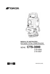
Once PC-CDU is launched, the Connection Parameters dialog box
displays (Figure 1-1).
Figure 1-1. Connection Parameters
This dialog box contains the following parameters needed to connect
a computer and a TPS receiver:
• Connection mode – used to set the type of connection.
– Direct: used when the computer and TPS receiver are directly
connected using a serial, parallel, USB or Ethernet port and a
cable.
P/N 31-000004-01
1-5
Introduction
Ethernet ports establish a direct connection between a
computer and a TPS receiver using a cable connection or
similar connection through the Internet. For more
information about communicating via Ethernet, see
“Establishing an Ethernet Connection” on page 1-13.
– Internet Client: used to get remote access to a TPS receiver
via the Internet. The remote receiver must be connected to a
computer, and this remote computer must be running
PC-CDU in Internet Server mode.
– Internet Server: used to provide access to a connected TPS
receiver via the Internet and a remote computer running
PC-CDU in Internet Client mode. Currently, Internet Server
mode only accesses one remote PC-CDU Internet Client at a
time. Both the Internet Server computer and the Internet
Client computer must have PC-CDU running in the
appropriate mode, as well as be connected to the Internet.
• Port settings – used to configure the computer’s communication
port and to set the desired settings of the receiver’s
communication port. These settings are applied after clicking
Connect.
– See the following sections for details on these settings for the
different connection types available with PC-CDU.
– RTS/CTS handshaking: ensures reliable data exchange
between the receiver and computer. Prior to selecting this
option, make sure that 1) both the computer and receiver
support RTS/CTS handshaking and 2) the serial cable being
used allows RTS/CTS handshaking.
– Infrared port: establishes an infrared connection when 1) an
appropriate external infrared adaptor is connected to the
selected serial port on the computer side, 2) the receiver’s
hardware supports an infrared port option, and 3) the Infrared
Port option is enabled in the receiver.
– Rec ID: only available for USB connections, used to select
the receiver, based on its unique electronic ID, to make a
connection with.
1-6
PC-CDU Reference Manual
Starting PC-CDU
• Program settings – used to apply configuration settings when
connecting to or disconnecting from the receiver.
– Passive mode: prevents PC-CDU from making changes to
receiver parameters. In this mode, the receiver’s pre-set
elevation mask defines the elevation angle for displaying
satellites on the Main window.
When turned off, PC-CDU automatically forces the Terminal
Elevation Mask to -90°, and all tracked satellites displays
(rather than just those above the mask angle). This setting
remains as long as PC-CDU is open. After closing PC-CDU,
the original mask is restored to the receiver. See “General” on
page 3-28 for information on setting the elevation mask.
– Manual mode only: allows PC-CDU to act as input/output
terminal for sending user commands to the receiver and
receiving information from the receiver without connecting to
the receiver.
– Timeout: establishes the number of milliseconds to wait
before trying the next baud rate while establishing a
connection with the receiver through a serial port.
– Restore the receiver’s original baud rate on Disconnect:
determines the receiver port’s original baud rate (before
running PC-CDU) and restores this setting after
disconnecting the receiver from PC-CDU.
• Internet (Client - Server) settings – used to enter Internet
connection parameters for connecting to or disconnected from a
remote receiver.
– Hostname: the name or IP address of the remote computer
running PC-DU Internet Server.
– TCP port: used to set the port needed through which to
connect to the Internet.
– Password: used to protect the PC-CDU server from
unauthorized access. Up to 128 alphanumeric characters may
be used.
– Display data on server: displays satellite information and the
antenna’s current position in the Main window.
P/N 31-000004-01
1-7
Introduction
– Log server events: creates a text log file (pccdu_server.log) in
PC-CDU’s working directory. This file contains some
information collected during the communication session
between the PC-CDU server and PC-CDU client. New
information is added to the file after another client connects
to the PC-CDU server.
– DNS lookup: includes the DNS address in the
“pccdu_server.log” file; otherwise, this file includes the IP
addresses only.
Establishing a Serial Port Connection
To establish a connection between a computer and the receiver using
serial ports, follow these steps:
1. Connect an available receiver port (usually port A) to a
communication port on the computer using a receiver-tocomputer RS-232 serial cable.
2. Turn on the receiver.
If the receiver does not have power, connect it to a power source.
Refer to the receiver’s documentation for this information.
3. Start PC-CDU and select the following parameters:
• Port list – select the computer serial port (COM1, COM2,...)
to use for the connection.
• Baud rate – select the desired baud rate for communication
between the receiver port and computer port.
• RTS/CTS handshaking – enable
• Infrared port – enable only if establishing a connection
between the receiver and computer via an infrared adaptor.
See the requirements on page 1-6 for details.
4. Click Connect. See Figure 1-1 on page 1-5 for an example of the
Connection Parameters dialog box for this connection type.
1-8
PC-CDU Reference Manual
Starting PC-CDU
Establishing a Parallel Port
Connection
Before connecting the receiver and computer using parallel ports and
the corresponding cable, make sure the following requirements are
met:
• The computer runs under Windows 95, 98 or ME.
• The computer’s parallel port has been configured as ECP or
ECP+EPP.
• The Parallel Port option has been enabled in the receiver.
NOTICE
If run on a Windows NT/2000/XP computer,
PC-CDU does not allow connection to the receiver
via parallel ports.
To establish a connection between the computer and the receiver
using parallel ports, follow these steps:
1. Connect the receiver’s parallel port (usually marked “Parallel”) to
a parallel port on the computer using the receiver-to-computer
parallel cable.
2. Turn on the receiver.
If the receiver does not have power, connect it to a power source.
Refer to the receiver’s documentation for this information.
3. Start PC-CDU and select the following parameters:
• Direct – enable.
• Port list – select the computer serial port (LPT1, LPT2,...) to
use for the connection.
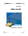
4. Click Connect (Figure 1-2 on page 1-10).
P/N 31-000004-01
1-9
Introduction
Figure 1-2. Parallel Port Connection Parameters
Establishing a USB Connection
Before connecting a USB equipped TPS receiver with the computer’s
USB port, make sure that the USB port option is enabled in the
receiver and that the TPS USB driver is installed on the computer.
Checking for the USB Option
Even if the receiver has a USB port, the option may not be enabled.
To verify whether or not the USB Port option is enabled, use a direct
serial cable connection. Once connected, click Tools Receiver
options.
• If enabled, “yes” displays in the Current column of the USB Port
option.
• If disabled, “no” displays in the Current column of the USB Port
option.
1-10
PC-CDU Reference Manual
Starting PC-CDU
Installing the TPS USB Driver
The driver installation procedure varies slightly depending on the
operating system used. For detailed information on the driver
installation for your specific operating system, see the appropriate
section in Appendix C.
NOTICE
The procedure below refers to the USB driver
version 2.0.0.2 or newer.
In general, the installation procedure is as follows:
1. Visit the Topcon website and log into the secure site. Navigate to
the GPS software downloads page.
2. In the PC-CDU MS section of the page, click tps_usb.zip to
download the compressed file to your computer. Click Save to
continue with the download.
3. Specify the destination (disk drive/folder) for the archive file and
click Save. Wait for the archive file to download onto your
system.
4. Extract the following files into a new folder.
• Tpsusbio.inf
• Tpsusb98.sys
• Tpsusbio.sys
5. Connect the receiver to the computer through the supplied USB
cable. Turn on the receiver.
6. The Windows operating system automatically detects the new
hardware device. Follow the on-screen instructions to finish the
installation process.
After Windows finishes installing the driver, you are now able to
connect the receiver and the computer using USB ports.
P/N 31-000004-01
1-11
Introduction
Connecting via USB
NOTICE
A USB connection cannot be established if using a
computer with Windows 95/NT operating system.
To establish a connection with the receiver using USB ports, follow
these steps:
1. Insert the USB cable into the USB port of the receiver. Plug the
opposite end of this cable into the USB port on the computer.
2. Turn on the receiver (and the computer, if needed).
If the receiver does not have power, connect it to a power source.
Refer to the receiver’s documentation for this information.
3. Start PC-CDU and select the following parameters:
• Direct – enable.
• Port list – select the computer’s USB port (USB) to use for
the connection.
• Rec ID – select the electronic ID of the receiver to connect
with.
4. Click Connect (Figure 1-3).
Figure 1-3. FUSB Connection Parameters
1-12
PC-CDU Reference Manual
Starting PC-CDU
Establishing an Ethernet Connection
TPS receivers can use the following two Ethernet-based methods for
communication:
• Communication with a receiver directly connected to a computer.
• Communication with a receiver connected to an existing TCP/IP
Ethernet network.
Connecting Directly via Ethernet
Use a direct Ethernet connection to test this connection before
connecting to an active TCP/IP network, or when an Ethernet network
is unavailable.
NOTICE
Use this method for preliminary tests before using
the receiver on an active TCP/IP network.
Before establishing the connection, make sure you have the
following:
• A computer with an Ethernet card installed and the TCP/IP
protocol configured.
• A TPS receiver with a physically installed Ethernet port and the
Ethernet port option enabled.
• The following cables:
– Ethernet adapter (p/n 14-008032-01)
– an Ethernet cross-over cable (this cable is typically available
from a local computer store or an online computer stores)
– an RS-232 cable (p/n 14-008005-02) to configure the IP
settings of the receiver
The following procedure describes how to connect the receiver
directly to a computer using Ethernet ports. The example in this
procedure uses a protocol with the following settings:
• IP address – 192.168.0.1
P/N 31-000004-01
1-13
Introduction
• Gateway – 192.168.0.3 (because only two devices are directly
connected and have no connections to another network, the
gateway address can be set to all zeros).
• Subnet mask – 255.255.255.0
You should have already installed an Ethernet card and configured the
TCP/IP protocol on your computer.
1. See “Establishing a Serial Port Connection” on page 1-8 for
connecting the computer and receiver using a serial cable.
2. Once connected, click Configuration Receiver Ports
Ethernet.
3. Select the following IP settings for the receiver:
• IP Address – enter the same value as the computer’s IP
address, but increment the last number by one. The last
number must differ from the computer's IP address but be
within the 0 to 255 range (for example, 192.168.0.2).
• IP Mask – enter the same number used for the computer.
• Gateway – enter the same number used for the computer.
4. In the Telnet Settings area, leave all settings as is, but ensure that
TCP port is set to 8002.
Record the value in the Network Password field (if no password is
needed, leave this field blank).
5. Click Apply then OK to set the parameters.
6. Click Tools Reset receiver to restart the receiver.
7. Click File Disconnect.
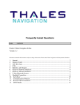
8. Connect the Ethernet cables (Figure 1-4 on page 1-15):
• Insert the seven pin connector of the Ethernet adapter into the
ETHR port of the receiver.
• Connect the other end of this adapter to the Ethernet
crossover cable (either end).
• Plug the second end of the crossover cable into the Ethernet
jack on the back of the computer.
1-14
PC-CDU Reference Manual
Starting PC-CDU
Figure 1-4. Direct Ethernet Connection – Hardware Setup
9. In PC-CDU, click File Connect and select or enter the
following settings:
• Connection mode – Direct
• Port – ETHR
• TCP port – 8002
• Host name – IP address assigned to the receiver in step 3 on
page 1-14
• Password – the same series of characters specified for the
receiver in step 4 on page 1-14, or leave blank if no password
10. Click Connect (Figure 1-5 on page 1-16).
P/N 31-000004-01
1-15
Introduction
Figure 1-5. Ethernet Connection Parameters
After establishing a live connection, the current connection type
(Ethr) and the receiver’s IP address display in the bottom left corner
of the PC-CDU Main window (Figure 1-6).
Figure 1-6. PC-CDU Main Window – Ethernet Connection Established
Connecting via an Existing TCP/IP Ethernet
Network
Use this method to connect the receiver to the Internet and to access
the receiver over a local area network (LAN). Before establishing the
connection, make sure the following components are available:
• An operational TCP/IP LAN or a connection to the Internet
• The following cables:
– Ethernet adapter (p/n 14-008032-01)
– straight-through Ethernet cable (this cable is available from a
local computer store or from many online computer stores)
1-16
PC-CDU Reference Manual
Starting PC-CDU
– an RS-232 cable (p/n 14-008005-02) to configure the
receiver’s IP settings
• A TPS receiver with an installed Ethernet port and the
corresponding option enabled. To verify whether or not the
Ethernet options are enabled using the Option Manager dialog
box in PC-CDU (click Tools Receiver options).
– “Ethernet Port” must be set to “yes” the Current column.
TCP Connections must range from 1 to 5.
– “FTP Connections” must be set to 1 (for FTP connections
only).
• For more information about receiver options, including Ethernetrelated options, see Table 3-5 on page 3-77.
The following procedure describes attaching the receiver to an
existing network.
NOTICE
When connecting TPS receivers to a network, work
closely with the system administrator to ensure
successful connections. Each receiver requires the
following: A unique static IP address whether or not
a Dynamic Host Configuration Protocol (DHCP) is
used on the network, a subnet mask, and a default
gateway.
1. Connect the computer and the receiver using the RS-232 serial
cable.
2. Run PC-CDU. Select appropriate communication settings for
connection via serial port and then click Connect. See
“Establishing a Serial Port Connection” on page 1-8 for details.
3. Click Configuration Receiver Ports Ethernet.
4. Specify the IP Address, IP Mask, and Gateway settings for the
receiver.
CAUTION
P/N 31-000004-01
If in doubt about which IP settings are safe to use,
consult your system administrator.
1-17
Introduction
5. Configure Telnet Settings and Network Password. The
following settings may be used:
6.
7.
8.
9.
10.
• TCP port – 8002 (default value). This is the port on which the
receiver listens for telnet-like connections. The receiver
allows up to five simultaneous telnet-like connections.
• Timeout – 600 (default value). This parameter sets the
amount of time in seconds the receiver allows an inactive
connection to remain open. After this time, the receiver
terminates the unused connection.
• Network Password – an arbitrary sequence of characters (to
not use a password leave this field blank).
Configure FTP Settings (optional). Use the following settings:
• TCP port – 21 (default value). This is the port on which the
receiver listens for FTP connection. The receiver allows only
one FTP connection at a time.
• Timeout – 600 (default value). This parameter sets the length
of time in seconds the receiver allows an inactive connection
to remain open. After this time, the receiver terminates the
unused connection.
Click Apply then click OK.
Click Tools Reset receiver to restart the receiver.
Click File Disconnect.
Connect the Ethernet cables (Figure 1-7 on page 1-19).
• Insert the seven pin connector of the Ethernet adapter into the
ETHR port of the receiver.
• Connect the other end of this adapter to the Ethernet straightthrough cable (either end).
• Plug the second end of the straight-through cable into the
Ethernet jack on the LAN hub or switch.
1-18
PC-CDU Reference Manual
Starting PC-CDU
Figure 1-7. Receiver on LAN – Hardware Setup
TIP
At this point, check that the receiver responds to the
ping command. From the Windows command
prompt or Run dialog box, type: “ping [receiver’s
IP address]” (for example, ping 195.105.138.43). If
the receiver responds, continue with step 11. If it
does not respond, double-check the LAN
connections and addresses.
11. In PC-CDU, click File Connect and specify the following
settings:
• Connection mode – Direct
• Port – ETHR
• TCP port – 8002
• Host name – IP address assigned to the receiver in step 4.
P/N 31-000004-01
1-19
Introduction
• Password – the same series of characters specified for the
receiver in step 5 or leave it blank to not use a password.
12. Click Connect (Figure 1-5 on page 1-16).
After establishing the connection and the current connection type
(Ethr), the receiver’s IP address displays in the bottom left corner of
the PC-CDU Main window.
Connecting to the receiver over a TCP/IP network provides the same
functionality as a cable connection. Other functionality includes
transferring files from the receiver over a TCP/IP network using FTP
and connecting up to five remote telnet-like terminals to the receiver.
For transferring raw data files from the receiver to the remote
computer using FTP, see “How to Download Files to a Remote
Computer Using FTP” on page 2-6.
Establishing an Internet Client–
Server Connection
An Internet connection can be used to connect to a remote receiver
connected to a computer running PC-CDU in “server” mode. A
client-server connection allows a remote receiver to be accessed,
maintained, managed, and updated as if the “client” were directly
connected to the receiver.
Internet Server Mode
In Internet Server Mode, the receiver must be directly connected to
the computer running PC-CDU server using one of the cable or
ethernet connections described above. The computer running
PC-CDU must have a live connection to the Internet.
To establish a connection with the receiver using PC-CDU, follow
these steps:
1. Start PC-CDU and select the following settings:
• Internet Server – enable.
• TCP port – enter the TCP port number (if needed); 8000 is
the default.
1-20
PC-CDU Reference Manual
Starting PC-CDU
• Password – enter the password needed to access the
connected receiver.
• Log server files – enable.
2. Click Connect (Figure 1-8).
Figure 1-8. Internet Server Connection Parameters
After connecting to the receiver, the main screen and server screen
displays (Figure 1-9).
Figure 1-9. Internet Server Started
The Server dialog box allows a user running PC-CDU Server to
communicate with the corresponding PC-CDU Client. In addition,
the server screen displays information about the server’s current
status.
P/N 31-000004-01
1-21
Introduction
Internet Client Mode
In Internet Client Mode, a remote receiver may be accessed for
monitoring, configuring, and managing the receiver. The computer
running PC-CDU must have a live connection to the Internet.
After establishing a connection to the remote receiver, the user can
control this receiver as if the user’s computer were directly connected
to the receiver, such as send commands to the remote receiver,
download log files from the receiver’s memory, and so on. Before
configuring the PC-DCU client parameters, have the following
information about the PC-CDU server available:
• IP or DNS address
• TCP port number
• Password (if necessary)
TIP
In the Host name edit box, enter either the server’s
IP address (such as, 194.135.59) or its DNS address
(such as, pab.topconps.com).
1. Start PC-CDU and select the following settings:
• Internet Client – enable.
• Host name – enter the IP address of the computer running
PC-CDU Server
• TCP port – enter the TCP port number (if needed); 8000 is
the default
• Password – enter the password needed to connect with the
server.
• DNS lookup – enable.
2. Click Connect (Figure 1-10 on page 1-23).
1-22
PC-CDU Reference Manual
Starting PC-CDU
Figure 1-10. Internet Client Connection Parameters
After connecting to the receiver, the main screen and the client screen
display (Figure 1-11).
Figure 1-11. Internet Client Started
The Client dialog box allows a user running PC-CDU Client on one
end to exchange messages with a user running PC-CDU Server on the
other end. Messages sent from the client to the server are preceded by
the character “>”. Messages sent from the server to the client begin
with the character “<”. The last received message is topmost in the
list.
P/N 31-000004-01
1-23
Introduction
Closing PC-CDU
NOTICE
Disconnecting the receiver from the computer
before exiting prevents conflicts with serial port
management.
To disconnect from the receiver, click File Disconnect. The
disconnect process results in the following:
• Turning off RTS/CTS handshaking.
• Resetting the receiver control Terminal Elevation Mask to its
original value (only if the Passive mode checkbox has not been
deselected).
• Resetting the baud rate to 115200 if the receiver’s original baud
rate that the receiver has before running PC-CDU exceeded
115200.
• Restoring the original baud rate if the Restore the receiver’s
original baud rate on Disconnect parameter has been selected.
To quit PC-CDU, click File Exit.
Although the connection is broken if exiting before disconnecting,
conflicts may occur with the serial port because the items in the list
above are still active.
1-24
PC-CDU Reference Manual
Chapter 2
PC-CDU Getting Started
Guide
This chapter contains a number of step-by-step instructions that will
walk you through the most frequently used software procedures,
focusing only on the configuration procedures most likely to be used.
Because it is a quick reference, this chapter does not contain a
detailed description of the settings and parameters. For detailed
information about the dialog boxes and fields in PC-CDU, refer to the
corresponding sections in Chapter 3.
How to Connect to the
Receiver
Physically connect the receiver and a computer using either a serial,
parallel, USB, or Ethernet cable.
• See “Establishing a Serial Port Connection” on page 1-8 for a
serial port connection procedure.
• See “Establishing a Parallel Port Connection” on page 1-9 for a
parallel port connection procedure.
• See “Establishing a USB Connection” on page 1-10 for a USB
port connection procedure.
• See “Establishing an Ethernet Connection” on page 1-13 for an
Ethernet port connection procedure.
P/N 31-000004-01
2-1
PC-CDU Getting Started Guide
How to Navigate through the
Software
Moving through PC-CDU is like moving through any other Windows
program: use the mouse to select desired functions and options; use
the Tab key to move from field to field.
Shortcut keys provide a quick way to perform common functions. If a
menu function has associated shortcut keys, the key combination will
be shown to the right side of the menu item (Figure 2-1).
Shortcut
Keys for
Menu Items
Figure 2-1. Example of Shortcut Keys Associated with Menu Items
How to Start Data Logging...
The primary purpose for configuring the receiver is to manage data
logging, either to the receiver’s memory or directly to the computer.
...To the Receiver Memory
1. Click File File Manager.
2. Click the Current log file tab and set the following parameters:
• File name – type name of the file to which the receiver will
log data
• Recording interval – set the data logging interval
• Elevation mask – set the elevation cut-off angle
• Site parameters – click to enter the site name and antenna
details
3. Click OK and then Start. A new log file will be created and the
receiver will start recording data into the file.
For more information, see “Current Log File” on page 3-14.
2-2
PC-CDU Reference Manual
How to Start Data Logging...
...On the Computer
1. Click File Real-Time Logging.
2. Click the Select output path tab and navigate to and open the
folder in which to download and store log files.
Or, type a new folder in which to download and store files.
3. Select the desired file creation mode, set the following parameters
(Table 2-1), and click Start.
Table 2-1. File Creation Mode Options
If “Single file” selected...
If “Multiple files” selected...
• Save to
• Recording interval field (data logging
interval)
• Site parameters (click and enter the site
name and antenna details, then click
OK)
• Elevation mask
• Prefix
• Numbering
• Start Count (if Ascending Count
selected)
• New file every
• Overwrite existing files (as needed)
• Autoconvert to RINEX (click Setup
converter to adjust the converter’s
settings)
• Recording interval
• Elevation mask
• Site parameters (click and enter the site
name and antenna details, then click
OK)
• Elevation mask
For more information, see “Single File” on page 3-19 and “Multiple
Files” on page 3-20.
P/N 31-000004-01
2-3
PC-CDU Getting Started Guide
How to Automatically Convert
Real-Time TPS Raw Data Files
to RINEX
While logging receiver raw data files to the computer, PC-CDU can
automatically convert the files from TPS format to RINEX format.
Deleting source files (if raw data files are not required) after a
successful conversion will save computer disk space.
1. Click File Real-Time Logging.
2. Click the Select output path tab and navigate to and open the
folder in which to download and store the original tps log files
and their RINEX counterparts.
Or, type a new folder in which to download and store files.
3. Select the Multiple files tab, and set the following parameters:
• Prefix
• Numbering
• Start Count (if Ascending
Count selected)
• New file every
• Overwrite existing files (as
needed)
• Recording interval
• Elevation mask
4. Enable the Autoconvert to RINEX and click Setup converter.
5. Set, if required, the following RINEX converter parameters and
click OK:
•
•
•
•
•
Run by
Observer
Agency
Antenna # (serial number)
Antenna type (antenna’s
NGS description)
• Comment
• Marker name
• Converter Application
• Exclude GPS and/or Exclude
GLONASS
• Exclude L1 and/or Exclude L2
• Delete source JPS files...
• Additional options
6. Click Start.
For more information, see “Multiple Files” on page 3-20 and
“Converter to RINEX Setup” on page 3-22.
2-4
PC-CDU Reference Manual
How to Stop Data Logging...
How to Stop Data Logging...
Once the data logging session has completed, stopping the data
logging will prevent files from being erased or the receiver’s/
computer’s memory from becoming full.
...To the Receiver Memory
1. Click File File Manager.
2. Click the Current log file tab and click Stop.
...On the Computer
Click File
Real-Time Logging and click Stop.
How to Configure Automatic
File Rotation Mode
Automatic file rotation will close and open new files in the receiver
memory, logging raw data to these files according to the userspecified schedule. AFRM may delete the earliest files when no free
memory remains to make space for new data logs.
1.
2.
3.
4.
Click Configuration Receiver.
Select the Minter tab.
In the File Creation mode area, select AFRM.
In the Automatic File Rotation Mode (AFRM) parameters area,
set the following parameters and click Apply:
• Period
• Phase
• Files (total)
• Automatically remove old files
5. To start data logging in AFRM mode, use the MINTER’s FN
button as you usually do for recording a single raw data file.
For more information on the AFRM mode, see to “MINTER” on
page 3-31.
P/N 31-000004-01
2-5
PC-CDU Getting Started Guide
How to Download Files to a
Computer Using File Manager
When logging data to the receiver, files will need to be downloaded
for post-processing and to manage the receiver’s memory (through
file deletion). This procedure downloads files to a computer directly
connected to the receiver.
1. Click File File Manager.
2. Select the Download path tab.
3. Navigate to and open the folder in which to download and store
files.
Or, type a new folder name and click Create to create a new
folder in which to download and store files. Open this new folder.
4. Select the Download files tab and select the file(s) to download.
5. Click Download.
6. Once the files have been successfully downloaded, continue with
other operations.
How to Download Files to a
Remote Computer Using FTP
When logging data to the receiver, files will need to be downloaded
for post-processing and to manage the receiver’s memory (through
file deletion). This procedure downloads files to a remote computer
connected through an FTP site.
1. Configure your Ethernet-enabled receiver as shown in
“Connecting via an Existing TCP/IP Ethernet Network” on
page 1-16.
2. From a computer on which you want the files to be stored, open a
Web browser (for example, Internet Explorer).
3. In the Address bar of the browser, type the IP address of the
receiver to connect with (for example, ftp://63.106.139.235).
2-6
PC-CDU Reference Manual
How to Delete Files from the Receiver
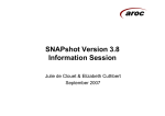
4. Enter a User Name and the Password intended for access. Click
Login.
5. Once the access has been verified, a list of log files in the receiver
displays. Select the files to download and right-click within the
selected area. Click Copy To Folder on the pop-up menu.
Figure 2-2. Login As Dialog Box and Copy Log Files
6. Navigate to and open the folder in which to download and store
files. Click OK and wait until all the selected files copy to the
computer.
7. Once the files have been successfully copied, continue with other
operations.
How to Delete Files from the
Receiver
Deleting files from the receiver’s memory creates space for new files.
1. Click File File Manager.
2. On the Download files tab, select the file(s) to delete.
3. Click Delete and Yes at the confirmation dialog box. PC-CDU
deletes the selected files.
4. Once the files have been successfully deleted, continue with other
operations.
P/N 31-000004-01
2-7
PC-CDU Getting Started Guide
How to Recover Deleted Files
Before recovering a deleted file, note the following important
recommendations:
• Do not record any new raw data files to the internal memory of
the receiver from which the file(s) was deleted. Recording new
files may overwrite (and permanently delete) the deleted file(s).
• Do not initialize the file system. This procedure permanently
erases all files inside the receiver.
• Do not try to remove the receiver’s Compact Flash card and read
its contents with a card reader.
1. Click File Manual Mode.
2. In the command line at the top of the Manual Mode dialog box,
type %%set,/par/dev/blk/a/removed,on and click
Send command.
3. Wait while the receiver re-mounts its file system (during this
process the REC LED blinks orange).
4. Once the file system is successfully re-mounted (the REC LED
stops blinking), close the Manual Mode dialog box and click
File File Manager.
5. Select the desired file and click Download.
In this mode, only the deleted file(s) will display.
6. After successfully downloaded the deleted file, restore the file
system to its normal state using one of the following procedures:
• Click Exit on the File Manager dialog box and open the
Manual Mode dialog box. In the command line, type
%%set,/par/dev/blk/a/removed,off and click
Send command.
• Click Exit on the File Manager dialog box, then click
File Disconnect. Finally, power cycle the receiver.
7. Wait while the receiver re-mounts its file system (during this
process the REC LED blinks orange).
8. Once the file system is successfully re-mounted, the REC LED
will stop blinking.
2-8
PC-CDU Reference Manual
How to Create a Receiver Configuration File
How to Create a Receiver
Configuration File
Creating and saving a receiver configuration file makes it easy to
apply quickly a pre-set configuration.
1. Click Configuration Receiver and click Save.
2. From the Save setup to a script dialog box, navigate to and open
the folder in which to save the file.
3. Enter the name of the configuration file to be created.
4. Select the extension for the file (usually “.tpc”).
5. Click Save.
NOTE
In the Configuration file, PC-CDU will store only
the current settings in the Receiver Configuration
dialog box and its sub-tabs.
How to Load the Configuration
File to the Receiver
Loading a saved configuration helps to quickly prepare the receiver
for surveying.
1. Click File Manual Mode.
2. In the bottom-left corner of the Manual Mode dialog box, click
Load script.
3. The Script file dialog box displays. Select the desired
configuration file and click Open. The filename displays in the
command line.
4. Click Send command. The file begins loading. Once the
>Done! string appears, the loading has completed and the
settings are applied to the receiver.
CAUTION
P/N 31-000004-01
Avoid loading the configuration files other than
those created specifically for the selected receiver.
2-9
PC-CDU Getting Started Guide
How to Enable WAAS Satellites
WAAS satellites provide error-corrected signals for improving GPS
positioning.
1. Click Configuration Receiver.
2. Select the Positioning tab then the WAAS tab and set the following
parameters:
• Channel 1 – enable
• Set WAAS – select the
WAAS satellite PRN
code
• as GPS – select the GPS
satellite PRN code
• Interpret message #0 as
message # – select 2
• Use Iono Corrections – select
Only
• Enable output of “true”
WAAS PRN numbers –
enable
3. If required, repeat step 2 for the second channel.
4. Click Apply.
For details on enabling satellites, see “Positioning” on page 3-34.
How to Configure a Base
Station for Broadcasting...
The Base station broadcasts messages that contain correction
information to Rover receivers. Topcon receivers support industry
standard RTCM and CMR message formats.
...RTCM Messages
1. In the Configuration menu, select the Receiver item.
2. Click the Base tab and select whether the using the phase center
L1 or antenna reference point for geodetic coordinates. Also
select the type of antenna.
2-10
PC-CDU Reference Manual
How to Configure a Base Station for Broadcasting...
3. Enter the latitude, longitude, and altitude (ellipsoidal height)
coordinates of the antenna position in the selected datum using
one of the following methods.
• If the Reference Geodetic Coordinates are known, enter the
coordinates.
• Click Get from receiver to use the current antenna position
(that is, the most recent position produced by the receiver).
4. Enter the following settings to include in RTCM messages:
• the station ID for the
reference receiver
• the health status of the Base
receiver
• the maximum number of
satellites
• enable pseudo-range
smoothing
• the serial number and
setup ID for the receiver
• the system(s) used
• the type of
measurement(s)
5. Click the Ports tab. On the Serial tab, set the following
parameters for the port from which to generate RTCM messages
and click Apply then OK:
• Input – select Command
• Output – select one of the
RTCM message types
• Period
• Baud rate
• RTS/CTS – enable if
modem supports
hardware handshaking
For details on the Base tab and Ports tab settings, see “Base” on
page 3-40 and “Ports – Serial” on page 3-46.
P/N 31-000004-01
2-11
PC-CDU Getting Started Guide
...CMR Messages
1. Click Configuration Receiver.
2. Click the Base tab and select whether the using the phase center
L1 or antenna reference point for geodetic coordinates. Also
select the type of antenna.
3. Enter the latitude, longitude, and altitude (ellipsoidal height)
coordinates of the antenna position in the selected datum using
one of the following methods.
• If the Reference Geodetic Coordinates are known, enter the
coordinates.
• Click Get from receiver to use the current antenna position
(that is, the most recent position produced by the receiver).
4. Enter the following settings to include in CMR messages:
• the station ID for the
reference receiver
• a short, long, and COGO
description of the object being
surveyed
• the state of the Base station
(static, kinematic, unknown)
• the message type to
associate with
GLONASS
measurements
• the type of
measurement(s)
5. Click the Ports tab. On the Serial tab, set the following
parameters for the port from which to generate CMR messages
and click Apply then OK:
• Input – select Command
• Baud rate
• Output – select one of the
CMR message types
• RTS/CTS – enable if
modem supports
hardware handshaking
• Period
For details on the Base tab and Ports tab settings, see “Base” on
page 3-40 and “Ports – Serial” on page 3-46.
2-12
PC-CDU Reference Manual
How to Configure Rover Station for Accepting...
How to Configure Rover
Station for Accepting...
The Rover station receives messages that contain correction
information from the Base station. Topcon receivers support industry
standard RTCM and CMR message formats.
...RTCM Messages in DGPS mode
1. Click Configuration Receiver.
2. Click the Rover tab, set the following parameters and click
Apply:
• Positioning Mode – enable DGPS (Code Differential).
• Multi-base – adjust settings if using two to five Base stations.
• Use the default values for the remaining settings.
3. Click the Ports tab. On the Serial tab, set the following
parameters for the port on which to accept RTCM messages and
click Apply then OK:
• Input – select RTCM
• Output – select None
• Baud rate
• RTS/CTS – enable if
modem supports
hardware handshaking
For details on the Rover tab and Ports tab settings, see “Rover” on
page 3-43 and “Ports – Serial” on page 3-46.
P/N 31-000004-01
2-13
PC-CDU Getting Started Guide
...RTCM Messages in RTK mode
1. Click Configuration Receiver.
2. Click the Rover tab, set the following parameters, and click
Apply:
• Positioning Mode – enable RTK Fixed.
• Use the default values for the remaining settings.
3. Click the Ports tab. On the Serial tab, set the following
parameters for the port on which to accept RTCM messages and
click Apply then OK:
• Input – select RTCM
• Output – select None
• Baud rate
• RTS/CTS – enable if
modem supports
hardware handshaking
For details on the Rover tab and Ports tab settings, see “Rover” on
page 3-43 and “Ports – Serial” on page 3-46.
...CMR Messages
1. Click Configuration Receiver.
2. Click the Rover tab, set the following parameters, and click
Apply:
• Positioning Mode – enable RTK Fixed.
• Use the default values for the remaining settings.
3. Click the Ports tab. On the Serial tab, set the following
parameters for the port on which to accept CMR messages and
click Apply then OK:
• Input – select CMR
• Output – select None
• Baud rate
• RTS/CTS – enable if
modem supports
hardware handshaking
For details on the Rover tab and Ports tab settings, see “Rover” on
page 3-43 and “Ports – Serial” on page 3-46.
2-14
PC-CDU Reference Manual
How to Set Raw Data & Position Update Rates to 20 Hz
How to Set Raw Data &
Position Update Rates to 20 Hz
This procedure will set the receiver to output measurement data and
position information at 20 Hz.
1. Click Tools Receiver options.
2. Make sure that the “Position update rate (Hz)” and “Raw data
update rate (Hz)” options display 20 in the Current column, then
click Exit.
3. Click Configuration Receiver.
4. Click the Advanced tab then the Raw Data Management tab, set
the following parameters, and click Apply:
• Raw Measurement Update Rate, Update Rate – set to 50 ms.
• Position Update Rage, Update Rate – set to 50 ms.
5. Click Refesh and examine the values in the Current Update Rate
fields, they should display 50.
6. Once verified, click OK.
When requesting any data recording or output with a period—that is,
a recording or output not directly supported by the current state of the
receiver—PC-CDU will launch the Output Period Setup Wizard. This
wizard will perform the same steps described above. For details on
the wizard, see Appendix D.
P/N 31-000004-01
2-15
PC-CDU Getting Started Guide
How to Enable a 1 PPS Output
For precise time information for synchronization or time transfer,
enable 1PPS output. 1PPS signals provide a precise time reference for
external devices.
1. Click Configuration Receiver.
2. Click the Events tab, set the following parameters, and click
Apply:
•
•
•
•
PPS A Enabled
Period
Offset (ms)
Offset (ns)
•
•
•
•
Period of ‘marked’ pulses (if required)
Edge
Ref. Time
Tied with Ref. Time
3. Repeat step 2 to enable the PPS B output (if required).
For details on setting the output, see “Events” on page 3-55.
How to Enable an Event
Marker Input
To have the receiver precisely record the time that an external event
occurs, enable event marker input. The source of events may be an
aerial camera, sounding equipment, etc.
1. Click Configuration Receiver.
2. Click the Events tab, set the following parameters, and click
Apply:
• Event A Enabled
• Clock Synchronization (leave
default)
• Edge
• Ref. Time
• Tied with Ref. Time
3. Repeat step 2 to enable the Event B input (if required).
For details on setting the event marker, see “Events” on page 3-55.
2-16
PC-CDU Reference Manual
How to Enable an External Frequency
How to Enable an External
Frequency
This procedure will enable an external frequency source connected
with the receiver’s External Frequency connector.
1. Click Configuration Receiver.
2. Click the Advanced tab then the External Frequency tab, set the
following parameters in the Frequency Source area, and click
Apply:
• Source – set to External
• External Frequency Source Parameters, Ext. freq. signal
amplitude or rate – set to a value from 2 to 40 MHz
depending on the frequency supplied by the external
frequency source.
3. Click Refesh and examine the fields Ext. frequency source status
and Ext. freq. signal amplitude, they should display locked and
ok, respectively.
4. Once verified, click OK.
For details on enabling an external frequency source, see “Advanced –
External Frequency” on page 3-62.
How to Output Position in a
Pre-defined Datum
Pre-defined datums are those embedded in the receiver firmware. TPS
receivers contain more than 200 pre-defined datums.
1. Click Configuration Receiver.
2. Click the Positioning tab, select the desired datum ID from the
Current Datum drop-down list, and click Apply.
NOTICE
P/N 31-000004-01
To view or log the receiver position in the selected
datum, use either NMEA messages (such as GGA)
or TPS proprietary ASCII messages (such as NP).
2-17
PC-CDU Getting Started Guide
How to Output Position in a
User-defined Datum
Selecting a user-defined datum will set up the receiver to compute a
position using defined ellipsoid and transformation values.
1. Click Configuration Receiver.
2. Click the Positioning tab and click Datum Parameters to set the
following parameters:
• Current Datum – select USER.
• Enter the corresponding values in the Reference Ellipsoid
parameters and Transformation parameters fields.
3. Click Apply then OK.
4. Click Apply on the Positioning tab.
NOTICE
To view or log the receiver position in the selected
datum, use either NMEA messages (such as GGA)
or TPS proprietary ASCII messages (such as NP).
For more details on these settings, see “USER Datum Parameters” on
page 3-38.
How to Restore Receiver
Default Settings
To restore the receiver’s default settings, do one of the following:
• Click Configuration
defaults.
Receiver. Click Set all parameters to
• Click Tools Clear NVRAM.
NOTICE
2-18
Clearing the NVRAM causes the receiver to delete
any data stored in its nonvolatile memory, including
receiver parameters, ephemeris and almanac data,
and receiver position. No raw data files will be
deleted.
PC-CDU Reference Manual
How to Check Firmware Version
How to Check Firmware
Version
You may need to know the firmware version of the GPS receiver in
certain situation, such as troubleshooting with TPS customer support
or determining which new firmware to upload.
1. Click Help About. The About PC-CDU dialog box displays.
2. Record the Firmware version field and click OK when done.
GNSS Receiver
Firmware Version
Figure 2-3. Check GPS Receiver Firmware Version
How to Check Receiver
Options
Receiver options enable or disable the various features available for
the receiver. Options can be purchased or leased.
1. Click Tools Receiver options. The Option Manager dialog box
displays and contains the following information:
• Option name – a name/description of the option.
• Current – the current status of the option.
• Purchased – if the option is purchased or not purchased.
• Leased – if the option is leased or not leased.
• Expiration date – the date a leased option will be disabled, if
applicable.
2. When finished, click Exit to close this dialog box.
P/N 31-000004-01
2-19
PC-CDU Getting Started Guide
How to Load New OAF to
Receiver
The Option Authorization File (OAF) contains the permissions
needed to enable (through a purchase or lease) the features available
for the receiver.
1. Click Tools Receiver options.
2. Click Load at the bottom of the Option Manager dialog box.
3. Navigate to the location of the new Option Authorization File.
OAFs have .tpo or .jpo extensions and are unique to each receiver.
4. Select the appropriate file and click Open. The new receiver
options will load onto the receiver and the Option Manager table
will update.
5. When finished, PC-CDU will restart the receiver to activate new
values for the options.
How to Disconnect from the
Receiver
Disconnecting from the receiver before exiting PC-CDU will prevent
management issues with the port PC-CDU used to access the receiver.
1. Click File
2. Click File
2-20
Disconnect.
Exit.
PC-CDU Reference Manual
Chapter 3
PC-CDU Software
Reference
This chapter provides detailed reference information on the Main
window, dialog boxes, tabs, parameters, and settings found
throughout the PC-CDU software interface.
Elements of the Main Window
After PC-CDU has established a connection between the computer
and receiver, the Main window displays (Figure 3-1). This window
has three areas: the Menu bar, the Satellites and Position area, which
is the largest part of the window, and the Status bar.
Menu Bar
Satellite&
Position Area
Status Bar
Figure 3-1. Main Window
Menu Bar
The Menu bar extends across the top of the Main window and
contains five menus (File, Configuration, Tools, Plots, and Help)
through which to access program functions. Alternatively, you can
use the shortcut keys (if available). The menu options are discussed in
more detail in later sections.
P/N 31-000004-01
3-1
PC-CDU Software Reference
Satellites and Position Area
The Satellites and Position area comprises of two panels, the GPS
Satellites panel on the left and the GLONASS Satellites on the right.
Between the two panels is the Geo|XYZ|Target box. The panels
display basic tracking information (parameters) for locked satellites.
These tracking parameters are described in Table 3-1. The
Geo|XYZ|Target box displays the antenna’s current position (if
available) and time-frequency parameters.
Table 3-1. Tracking Parameters Displayed in the Satellites Panels
Column
Description
#
GPS SV PRN. If the character “*” is shown next to PRN in
the column, this means that almanac data are unavailable for
the corresponding satellite.
Sn
GLONASS SV Orbital Slot Number. If the character “*” is
shown next to Sn in the column, this means that almanac data
are unavailable for the corresponding satellite.
Fn
GLONASS SV Frequency Number.
EL
Elevation angle in degrees. The signs “+” and “-”
immediately following the elevation angle indicate that the
corresponding satellites are either ascending or descending,
respectively. If a satellite is at maximum elevation, it is
marked with “^”.
AZ
Azimuth in degrees.
CA
Signal-to-Noise Ratio (C/No) in the C/A channel [dB*Hz].
P1
Signal-to-Noise Ratio (C/No) in the P1 channel [dB*Hz].
P2
Signal-to-Noise Ratio (C/No) in the P2 channel [dB*Hz].
2C
Signal-to-Noise Ratio (C/No) in the GPS L2C and
GLONASS L2 C/A channel [dB*Hz].
TC
Time elapsed since the last loss-of-lock in the C/A channel
for the corresponding satellite. This time is given in minutes
or, if the symbol “:” is specified in the column, in seconds.
3-2
PC-CDU Reference Manual
Elements of the Main Window
Table 3-1. Tracking Parameters Displayed in the Satellites Panels (Continued)
Column
SS
Description
Satellite navigation status. For a complete description of the
satellite navigation status structure, see Appendix D on
page D-1. If a satellite is not used in position computation, its
SS flag will be set to “-”. Otherwise “+” will be displayed.
The satellites panels have the following functionality:
• Double question marks (??) will display in the cells of a column
when parameters are unavailable for the satellite.
• Click the column’s heading to sort data in descending/ascending
order.
The Geo|XYZ|Target box has the following tabs (Figure 3-2):
• Geo – displays the current position of the receiver's antenna and
the time-frequency parameters describing the behavior of the
receiver's local oscillator.
• XYZ – displays the position of the antenna in Cartesian
coordinates.
• Target – displays various navigational information.
Figure 3-2. Geo|XYZ|Target Tabs
Table 3-2 on page 3-4 provides a description of each of the values in
these tabs.
P/N 31-000004-01
3-3
PC-CDU Software Reference
Table 3-2. Elements of the Geo|XYZ|Target Tabs
Field
Description
Geo tab related fieldsa
Lat
Geodetic latitude of the receiver antenna.
Lon
Geodetic longitude of the receiver antenna.
Alt
Ellipsoidal height of the receiver antenna.
XYZ tab related fields
X
Earth-Centered-Earth-Fixed WGS-84 X coordinate of the
receiver antenna.
Y
Earth-Centered-Earth-Fixed WGS-84 Y coordinate of the
receiver antenna.
Z
Earth-Centered-Earth-Fixed WGS-84 Z coordinate of the
receiver antenna.
Target tab related fields
Lat
Geodetic latitude of the target or of the receiver’s antenna.
Lon
Geodetic longitude of the target or of the receiver’s antenna.
ETT
Easting-to-Target in the local system with the origin at the
receiver.
NTT
Northing-to-Target in the local system with the origin at the
receiver.
DTT
Distance-to-Target.
CTT
Course-to-Target.
Geo and XYZ tabs common fields
Vel
(Magnitude of the) velocity (m/s).
RMS Pos
RMS position error (m). More precisely, this is the square root
of the trace of the position error covariance matrix.
RMS Vel
RMS velocity error (m/s). More precisely, this is the square root
of the trace of the velocity error covariance matrix.
3-4
PC-CDU Reference Manual
Elements of the Main Window
Table 3-2. Elements of the Geo|XYZ|Target Tabs (Continued)
Field
Description
Geo, XYZ, and Target tabs common fields
PDOP
Position Dilution of Precision.
Solution type
Standalone, Code differential, RTK float, or RTK fixed.
LQ
This field reflects the status of the received differential messages
and contains the following information:
• Data link quality in percentage
• Time (in seconds) elapsed since the last received message
• Total number of received correct messages
• Total number of received corrupt messages
LQ
(continued)
If the receiver is not (for some reason) receiving differential
corrections or if none of the ports has been configured to receive
differential corrections, the LQ field will either be empty or it
will look like this: 100%(999,0000,0000). Currently the values
for this field are obtained from the [MS] message.
Receiver time
This field shows the receiver's current time within the day. This
value is taken from the message [~~]b. For more information
about [~~], refer to the GRIL Reference Manual.
Receiver date
This field shows the receiver's current date as specified in the
corresponding [RD] message.
Clock offset
This field describes the time derivative of (Tr - Trr), where Tr
designates the receiver time and Trr designates the receiver
reference time. For more information about Tr and Trr, refer to
the GRIL Reference Manual. This parameter is obtained from
the [DO] message and is expressed in parts per million (ppm).
Osc. offset
The parameter describes the difference between the VCO's
nominal and quiescent frequencies. It is derived from the
message [OO] and is expressed in ppm.
Tracking time
This field shows the time elapsed since the last complete loss-oflock event in the receiver's C/A channels as specified in the
corresponding [TT] message.
a. These geodetic coordinates are always computed in WGS-84.
b. Currently, the message [~~] reports the time within day in GPS time
scale only.
P/N 31-000004-01
3-5
PC-CDU Software Reference
The Geo|XYZ|Target box has the following functionality
• To set the target coordinates equal to the current receiver
coordinates, double-click on the Lat or Lon field of the Target tab.
• To reset the timer to 00:00:00, double-click somewhere in the
hour:min:second area.
Status Bar
The Status bar provides auxiliary information while using PC-CDU.
This information includes the connection status, current
communication settings, various types of messages (for example,
error messages) and time since the connection to the receiver has been
established.
3-6
PC-CDU Reference Manual
Quick Menu Reference
Quick Menu Reference
The following graphs show the menu structure for the five PC-CDU
menus. The remaining sections in this chapter describe these menus,
options, and parameters in detail.
Menu Items
Connect Disconnect File Manager
Real-Time Logging Manual Mode Exit
Dialog Boxes
File
Connection
parameters
Real-Time Logging Manual Mode
File Manager
Sub-Dialog Boxes
Tabs
Download files
Current log file
Download path
Site Configuration
P/N 31-000004-01
Single file
Multiple files
Select output path
Converter to
RINEX Setup
Script file
Log file
Select output path
(for RINEX converter)
3-7
PC-CDU Software Reference
Menu Items
Receiver
Dialog Boxes
Receiver
Configuration
Tabs
Configuration
General
MINTER
Positioning
Base
Rover
Ports
Advanced
Radio
Site
Target position
Sub-Dialog Boxes
& Sub-Tabs
RFM96
Datum
Parameters
Site
Configuration
Target Position
RFM96
Configuration
Connect
Configuraiton
Anti-Interference
Multipath Reduction
Loop Management
External Frequency
Raw Data Management
Options
Serial
Parallel
Modem
USB
Ethernet
TCP
Save setup
to a script
Initialize file system
Clear NVRAM
Reset Receiver
Receiver options
Initialize file system
Clear NVRAM
Reset Receiver
Option Manager
Sub-Dialog
Boxes
Dialog Boxes
Menu Items
Tools
3-8
Select options
file
PC-CDU Reference Manual
Quick Menu Reference
Scatter
Satellites
Position
Configuration
Scatter
Satellites
Position
Plots Configuration
Sub-Dialog
Boxes
Dialog Boxes
Menu Items
Plots
ElevationMaskForm
Color
About
About PC-CDU
Sub-Dialog
Boxes
Dialog Boxes
Menu Items
Help
P/N 31-000004-01
Save Receiver
Information to file
3-9
PC-CDU Software Reference
File Menu
The File menu contains options for connecting with/disconnecting
from the receiver, managing the download and real-time logging of
data files, putting the receiver in Manual Mode, and exiting the
program.
Connect
The Connection Parameters dialog box contains parameters for
establishing a connection between the receiver and a computer.
Figure 3-3. Connection Parameters
See “Starting PC-CDU” on page 1-5 for more information on the
parameters available for connection.
Disconnect
The Disconnect menu option closes the connection between a
receiver and computer.
WARNING
Disconnecting the receiver from the computer
before exiting prevents conflicts with serial port
management.
See “Closing PC-CDU” on page 1-24 for more information.
3-10
PC-CDU Reference Manual
File Menu
File manager
The File Manager dialog box manages data logging and log files
collected with a TPS receiver.
Download Files
The Download files tab displays files for download to a computer or
deletion from the receiver’s memory.
Figure 3-4. Download Files
The upper portion of the Download files tab has the following fields:
• Total memory – the total amount of memory available in the
connected receiver.
• Free memory – the amount of memory currently available in the
connected receiver.
The primary portion of the Download files tab has the following
fields:
• Name – the name of the log file.
• Size – the size of the log file.
• Date – the date the log file was recorded.
• Time – the time the log file was recorded.
• Download status – during a download session, indicates the
following status of the file(s) being downloaded:
– Blue icon: during download, indicates that the file is in the
queue for downloading.
P/N 31-000004-01
3-11
PC-CDU Software Reference
– Red icon: during download, indicates that the file is currently
being downloaded.
– Green icon: during download, indicates that the file was
successfully downloaded.
The lower portion of the Download files tab has the following fields:
• Save to – the path and location on the computer to which files will
be downloaded. Use the Download path tab to select the location.
• Exclusive mode – when enabled, increases the speed of data
transfer, especially if a baud rate of 115200 or higher has been
set. Using this option will disable most processes running inside
the receiver (including the satellite tracking process) in order to
ensure the highest possible file transfer speed. PC-CDU will
automatically close the current log file before downloading.
When disabled, the current log file can be downloaded without
being closed. This means that the download process will proceed
until the “end-of-file” point has been reached; however, new data
will continue to be logged to the file. This can cause the following
when downloading a file:
– Occasionally cause the download indicator to display values
greater than 100%.
– Cause the last record in the downloaded file to be corrupt.
• Using – the computer port used for downloading files (the same
port used to connect with the receiver and computer).
• Block size – the amount of data, in bytes, to download at a time.
The buttons on the Download files tab have the following functions:
• Download – begins the download process for selected log files. A
download path must be specified before beginning the download
process. See “Download Path” on page 3-16 for details.
• Stop – stops the download process.
• Delete – deletes the selected log files. Inadvertently deleted log
files can be retrieved if the receiver has not been initialized or its
NVRAM cleared.
• Refresh – reloads the list of log files.
• Exit – closes the File Manager dialog box.
3-12
PC-CDU Reference Manual
File Menu
To select log files for downloading or deletion, use one of the
following methods:
• For adjacent files, click the first file. While holding the Shift key,
click the last file. All files between the two selected files will also
be selected.
• For a non-adjacent files, click the first file. While holding the
Ctrl key, click each desired file.
When downloading log files from a receiver, the files will retain their
original names and PC-CDU checks the destination folder for existing
files of the same name. If the destination folder already contains a file
with the same name as a file being downloaded, PC-CDU will ask to
overwrite the existing file or append new data to the existing file.
• If overwriting a file, the new file will replace the current file.
• If appending a file, the contents of the new file will be added onto
the contents of the existing file.
WARNING
Typically, only use the Append option if the
download process has been interrupted and is now
resuming.
Figure 3-5. Overwrite Confirmation Message
The status bar at the bottom of the Download files tab displays error
and other messages on the download status of log files.
P/N 31-000004-01
3-13
PC-CDU Software Reference
Current Log File
The Current log file tab displays current files and has fields for
creating new files.
Figure 3-6. Current Log File
The upper and primary portions of the Current log file tab have the
same fields as the Download files tab. See “Download Files” on
page 3-11 for details.
The lower portion of the Current log file tab has the following fields:
• Current file – the name of the file that data is being logged to.
• Size – the size of the current log file.
• File name – either the entered name of a new file or the name of a
selected file (double-click the file to select it for this field).
• Recording interval – the time in seconds between logging
recording. If the receiver does not support the entered interval, the
Output Period Setup Wizard will launch (see Appendix D for
details).
• Site parameters – opens the Site Configuration dialog box. See
“Site Configuration” on page 3-15 for details.
• Elevation mask – the minimum angle above the horizon, in
degrees, for satellites from which the receiver will record data.
The bottom row of buttons on the Current log file tab have the same
functions as those on the Download files tab. See “Download Files”
on page 3-11 for details.
3-14
PC-CDU Reference Manual
File Menu
Site Configuration
The Site Configuration dialog box applies antenna parameters to the
pccdu.ini file for data logging purposes.
Figure 3-7. Site Configuration
• Site Name – the name of the jobsite (up to 20 alphanumeric
characters).
• Antenna Status – the status of the antenna; either fixed or moving.
• Antenna Height – the height of the antenna measured from the
survey marker to the measuring mark on the antenna (either ARP
or SHMM).
• Slant – if selected, indicates that the height of the antenna was
measured at a slant (to the slant height measurement mark).
When not selected, indicates a vertical measurement (to the
antenna reference point).
• Antenna Type – the type of antenna.
• Send parameters automatically – sends site and antenna
parameters to the receiver each time a log file is created.
• OK – copies the settings to the pccdu.ini file and closes the dialog
box. After clicking Start on the File Manager dialog box, these
settings will be enabled and inserted into the newly created log
file (unless Send parameters automatically has been disabled).
• Send to receiver – sends new site parameters to the receiver log
file and the pccdu.ini file during logging.
• Cancel – closes the dialog box without saving the settings.
P/N 31-000004-01
3-15
PC-CDU Software Reference
Download Path
The Download path tab displays the destination path and folder in
which to download files.
Figure 3-8. Current Log File
• Left panel – contains the computer’s hard drive directory and
associated folders. Use the directory tree to navigate to the
desired location in which to download log files.
• Right panel – displays the files currently in the selected folder.
• Drive selection – selects the drive that contains the location in
which to download files.
• New folder – specifies the name of a new folder.
• Create – creates a folder with the entered name on the selected
drive.
Files will be stored in the last specified download path.
3-16
PC-CDU Reference Manual
File Menu
Real-Time Logging
The Real-Time Logging dialog box starts/stops logging data directly
to a computer connected to a TPS receiver.
Figure 3-9. Real-Time Logging
• GPS Satellites – displays information on signals from GPS
satellites. See “Elements of the Main Window” on page 3-1 for
more information.
• Receiver Position – along with information from the Geo tab (see
“Elements of the Main Window” on page 3-1 for more
information), the following log file details display:
– Elapsed time: the amount of time that has passed since the
current log file opened. The time is reset to 00:00:00 for each
new file.
– Received: the size of the log file in bytes. Click Stop to view
the final size of the log file.
• GLONASS Satellites – displays information on signals from
GLONASS satellites. See “Elements of the Main Window” on
page 3-1 for more information.
• Recording interval – the time in seconds between logging
recording. If the receiver does not support the entered interval, the
Output Period Setup Wizard will launch (see Appendix D for
details).
This setting only affects files recorded in this mode.
P/N 31-000004-01
3-17
PC-CDU Software Reference
• Site parameters – opens the Site Configuration dialog box. See
“Site Configuration” on page 3-15 for details.
• Start/Stop – starts or stops recording data to the file. When
stopping data logging, the file will also be closed.
• Exit – closes the dialog box.
• Elevation mask – the minimum angle above the horizon, in
degrees, for satellites from which the receiver will record data.
This setting also affects the Terminal Elevation Mask setting (see
“General” on page 3-28 for further information on this setting).
WARNING
WARNING
3-18
In real-time data logging mode, enable the RTS/
CTS handshaking checkbox and set the baud rate to
115200 or higher when connecting the receiver and
computer.
Unlike downloading recorded log files from the
receiver onto the computer, real-time data logging
does not use error detection/correction protocol in
the course of the data transfer. As a result, some
messages in the created TPS files may be corrupt
(due to the serial port overrun or similar problems);
that is, some of the transferred bytes may be lost on
the computer end.
PC-CDU Reference Manual
File Menu
Single File
The Single file tab displays satellite and log file information, as well
as applies file parameters to a single file during real-time data logging
to the computer.
Figure 3-10. Real-Time Logging – Single File
Along with the fields and button discussed in “Real-Time Logging”
on page 3-17, the Single file tab has the following fields:
• Save to – the name of the file in which to log data. By default, this
name will be the same as the name entered in the Site
Configuration dialog box.
• Output path – the location in which files will be saved. See
“Select Output Path” on page 3-24 for selecting this location.
P/N 31-000004-01
3-19
PC-CDU Software Reference
Multiple Files
The Multiple files tab displays satellite and log file information, as
well as applies file parameters to a multiple files during real-time data
logging to the computer.
Figure 3-11. Real-Time Logging – Multiple Files
Along with the fields and button discussed in “Real-Time Logging”
on page 3-17, the Multiple files tab has the following fields:
• Prefix – the beginning part of the name for each file. By default,
the site name entered in the Site Configuration dialog box will be
used.
• Numbering – the numbering scheme for file names. This number
will be added to the prefix of the file name.
– Date & Time: YDDDHHMM; where “Y” is the last digit of
the current year, “DDD” is the day of the year, “HH” is the
hour in the receiver time scale, and “MM” is the minutes in
the receiver time scale.
The date and time used for the filename corresponds to the
first epoch recorded into the file
– Ascending Count: the numeric portion of the file name will
vary between 0000 and 2 31 – 1 . This number will increase by
one with each file. (Selecting this option enables Start
Count.)
3-20
PC-CDU Reference Manual
File Menu
• New file every – the interval between closing one file and
opening the next file. Note that files may be shorter than the
interval entered in these fields.
– Enter an integer to measure the interval.
– Select the unit of time (day, hour, or minute).
• Autoconvert to RINEX – automatically converts new TPS files to
RINEX after closing the file. Some agencies and third-party
software only process RINEX files.
WARNING
The “tps2rin.exe” file is required for the
Autoconvert to RINEX function to work properly.
• Current file – the name of the current file being recorded.
• Start count – enabled when Ascending Count selected, the first
number to use for file counts. This number is added to the prefix
to create file names.
• Overwrite existing files – writes over existing files that have the
same name as new files. A warning will display after clicking
Start.
Figure 3-12. Overwrite Existing Files?
• Setup converter – accesses setup options for the tps2rin.exe
converter. For more information, see “Converter to RINEX
Setup” on page 3-22.
• Output path – the location in which files will be saved. See
“Select Output Path” on page 3-24 for selecting this location.
Figure 3-13 on page 3-22 shows an example of recording multiple
files. The graph shows a time scale divided into intervals equal to the
period specified in the New file every fields. After clicking Start, the
file records the time and file name and begins logging data. Once the
time interval has been reached, the file will be closed and a new file
P/N 31-000004-01
3-21
PC-CDU Software Reference
will open. The time duration of the second and all following files will
equal the selected file period.
After clicking Stop, PC-CDU will close the last file. Because the end
of the time interval may not have been reached, the last file can be
shorter than previous files.
Duration of first file
Duration of second file
0h00m00s
n
2n
3n
4n
Duration of last file
(i-1)n
i+1
= opening of first file
= closing of last file
n = period specified in “New file every”
Figure 3-13. Generation of Multiple Files
Converter to RINEX Setup
The Converter to RINEX Setup dialog box applies options to the
tps2rin.exe converter for the TPS file-to-RINEX data conversion.
Figure 3-14. Converter to RINEX Setup
Information entered here will be included in the header of the
corresponding RINEX files.
• Run by – name of the person or agency launching the converter.
• Observer – name of the person collecting the data.
• Agency – name of the agency responsible for collecting the data.
3-22
PC-CDU Reference Manual
File Menu
• Antenna # – serial number of antenna. This number twill be
copied into the RINEX files.
• Antenna type – description of antenna (use only antenna names
approved and standardized by NGS). This description will be
copied into the RINEX files.
• Comment – further notes about the job. Any text entered here will
appear in the header of each RINEX file to be generated.
• Marker name – survey marker name.
• Marker number – survey marker identification number.
• Application – the full path to the “tps2rin.exe” file.
• Browse – opens Windows Explorer for navigating to and
selecting the “tps2rin.exe” file.
• Exclude GPS and Exclude GLONASS – during the conversion,
leaves out all raw data measurements/ephemeris data
corresponding to GPS and/or GLONASS satellites from the
resulting RINEX files.
• Exclude L1 and Exclude L2 – during the conversion, leaves out
all L1 and/or L2 raw data measurements from the resulting
RINEX files.
• Delete source JPS files after successful conversion – remove the
original *.tps files once the conversion to RINEX format
successfully completes. Deleting source files (if raw data files are
not required) after a successful conversion will save computer
disk space.
• Additional options – applies any of the command-line switches
available for the RINEX converter to modify the converter’s
behavior. For more information about the switches, refer to the
Free Software section on the TPS GPS website
(http://www.topcongps.com/software/tps2rin.html).
P/N 31-000004-01
3-23
PC-CDU Software Reference
Select Output Path
The Select output path tab displays the path (disc and folder) where
logged raw data will be stored.
Figure 3-15. Real-Time Logging – Select Output File
• Left panel – contains the computer’s hard drive directory and
associated folders. Use the directory tree to navigate to the
desired location in which to download log files.
• Right panel – displays the files currently in the selected folder.
• Drive selection – selects the drive that contains the location in
which to download files.
• New folder – specifies the name of a new folder.
• Create – creates a folder with the entered name on the selected
drive.
Files will be stored in the last specified download path.
3-24
PC-CDU Reference Manual
File Menu
Manual Mode
The Manual Mode dialog box provides an interface to manually send
commands to a connected receiver and view the responses. For a
complete list of commands TPS receivers support, refer to the GRIL
Reference Manual.
WARNING
Become familiar with the GRIL Reference Manual
before sending commands via Manual Mode.
Figure 3-16. Manual Mode (with Sample Commands/Responses)
• Command line (and drop down box) – the currently entered
command to send to the receiver. The drop-down box contains the
last 20 command lines entered since connecting with the receiver.
• Main window – displays commands sent to the receiver and
responses from the receiver.
• Send command – sends the entered/selected command to the
receiver.
• Stop all messages – stops outputting messages from the receiver
to the current terminal.
• Clear window – clears all messages from the main window.
P/N 31-000004-01
3-25
PC-CDU Software Reference
• Exit – closes the dialog box.
• Disconnect – disconnects the computer and receiver and keeps
any configuration changes.
• Start logging – copies the current Manual Mode session’s
commands and responses to a file on the computer.
• Load Script – sends a pre-recorded script file to the receiver. The
location of a loaded script displays next to the button.
TIP
Script files make sending commands to the receiver
a quick process.
• Edit Script – creates/modifies a script file of commands.
Exit
Closes PC-CDU.
WARNING
3-26
Simply closing PC-CDU does not disconnect the
receiver from the computer. For serial port
management, click File Disconnect before
exiting.
PC-CDU Reference Manual
Configuration Menu
Configuration Menu
The Configuration menu contain options for configuring the receiver
as a Base or Rover, configuring the receiver’s ports, configuring raw
data logging, configuring the internal and an external antenna, and
entering target coordinates.
Receiver
The Receiver Configuration dialog box displays the receiver’s
current configuration, as well as provides fields and settings for
editing a configuration for a job.
Figure 3-17. Receiver Configuration
Buttons common to all tabs include the following:
• Refresh – updates the current tab with the latest information from
the receiver.
• Apply – sends configuration settings from the current tab to the
receiver without closing the dialog box.
• Ok – sends configuration settings from all tabs to the receiver and
closes the dialog box.
• Exit – closes the dialog box without saving changes (since the last
time the Apply button was used).
P/N 31-000004-01
3-27
PC-CDU Software Reference
• Save – saves the current receiver configuration to a script file.
Figure 3-18. Save Setup to a Script
• Set all parameters to defaults – returns all settings to factory
defaults.
General
The General tab contains basic antenna and power parameters
common to all receiver configurations.
Figure 3-19. Receiver Configuration – General
• Elevation mask (degrees) – the minimum angle above the
horizon, in degrees, for satellites from which the receiver will
record data.
• Antenna – selects the antenna type used with the connected
receiver, either Internal, External, or Auto.
• Antenna Status – shows the actual antenna the receiver uses.
3-28
PC-CDU Reference Manual
Configuration Menu
– Current Input: either “int” for internal antenna or “ext” for
external antenna.
– Ext. DC Status: shows if the external antenna draws DC
power; either “off” for no power, “normal” for normal power,
or “overload” if the antenna draws higher power than
expected or a short circuit occurs in the antenna or antenna
cable.
• Temperature – shows the receiver board's current temperature in
degrees of Celsius.
• Power – selects and shows the source of power.
– Mode: sets the desired power source for the connected
receiver (may vary depending on the connected receiver).
• Auto – receiver will automatically select the power
source.
• Mix – receiver will automatically consume power from
the source with the highest voltage.
• Battery A – receiver will consume power only from
battery A.
• Battery B – receiver will consume power only from
battery B.
• External – receiver will use an external power supply.
• Prefer A – receiver will use the batteries in sequence: first
A, then B, A, B, and so on. In this case, battery B will last
1 to 2 hours longer.
• Prefer B – receiver will use the batteries in sequence: first
B, then A, B, A, and so on. In this case, battery A will last
1 to 2 hours longer.
– Current mode: shows the current power source.
NOTE
P/N 31-000004-01
For the GR-3 receiver, this field shows “Extbat” if
the receiver consumes power from the battery
charging cradle.
3-29
PC-CDU Software Reference
• Charger – applies charging settings for the battery.
– Mode: the battery charging mode (may vary depending on the
connected receiver).
• On – receiver automatically detects and charges both
batteries.
• Off – receiver will not charge the batteries.
• Charge A – receiver will charge only battery A.
• Charge B – receiver will charge only battery B.
• Auto – receiver will automatically detect and charge the
detected batteries.
– Speed: sets the speed for a battery charge cycle (not available
for all receiver models); either “Normal” of “Fast”.
– Current mode: displays the battery currently being charged.
– Current (Amp): displays the actual battery charging current in
Amperes.
• Power output modes – only applicable to Odyssey, Odyssey-E,
and HiPer family receivers, governs power output to ports and
slots.
– Ports A, B: available for the Odyssey receiver, turns power
on/off for ports A and B.
– Port C: available for the Odyssey receiver, turns power on/off
for port C.
– Ports: governs power output on the serial ports.
• On – when the receiver is turn on, the power board power
all available serial ports. If the receiver is turn off, no
power will be sent to the ports.
• Off – power will not be powered, even if the receiver is
turned on.
• Always – all serial ports will be powered even if the
receiver is turned off.
– Slots: governs power output to the receiver’s internal slots.
• On – when the receiver is on, all internal slots will
receiver power. If the receiver is turned off, no power will
be sent to the slots.
3-30
PC-CDU Reference Manual
Configuration Menu
• Off – internal slots will not be powered, even if the
receiver is turned on.
• Always – all internal slots will be powered even if the
receiver is turned off.
• Voltages – the current power voltage state of the external power
supply (only if connected), receiver board (actual voltage),
batteries, charger (internal charger), and ports (first pin of each
port).
• Turn on/off Slots – only applicable to Odyssey-E, HiPer, and
GR-3 family receivers, enables the corresponding internal slots.
• Enable Low Power Mode – enables the receiver’s processor for
low power consumption.
MINTER
The MINTER tab contains receiver parameters that correspond to
MINTER operation and to data logging.
Figure 3-20. Receiver Configuration – MINTER
• Recording interval – specifies the interval to use for logging data
after pressing the FN key. This parameter applies to both Log file
and AFRM modes. If an incorrect recording interval is set for the
connected receiver, the Output Period Wizard will start (see
Appendix D for details). Values are 0 to 86400 seconds; the
default is 1 second.
P/N 31-000004-01
3-31
PC-CDU Software Reference
• Elevation mask for Log file – specifies the minimum angle for the
satellites whose data will be logged after pressing the FN key.
The default is 5 degrees.
• File name prefix – specifies the prefix added to data files after
pressing the FN key. Log files have a “<prefix><month><day>
<sequential alphabet letter>” format. The prefix can be up to 20
characters long; the default is “log”.
• Always append to the file – specifies the name of an existing file
to append new data to. The file name can be up to 20 characters.
• File Creation mode – determines the process for creating new
files after pressing the FN key.
– Log file: if enabled, closes the current log file; if disabled,
opens a new log files.
– AFRM: if enabled, disables this mode; if disabled, enables
this mode.
• Automatic File Rotation Mode (AFRM) parameters – closes
current files and opens new files (file rotation) according to the
entered parameters.
– Period (sec): specifies the time duration for log files created
in AFRM mode. Values are 60 to 86400; the default is 3600.
– Phase (sec): specifies the constant time shifts of log files
created in AFRM mode. Values are 0 to 86400; the default is
0 (zero).
– Files (total): specifies the total number of files to create
before turning off AFRM mode (not including the first file
created). Values are 0 to [231-1]; the default is 0 (zero). A
zero value will create an unlimited number of log files.
– Files (remain): specifies the number of files remaining before
AFRM mode turns off.
– Automatically remove old files: when no memory remains,
automatically removes the earliest log file. The receiver will
erase the file with the earliest time/date. The default is
disabled.
3-32
PC-CDU Reference Manual
Configuration Menu
• FN Key mode – programs the receiver’s reaction to the FN key.
– LED blink mode switch: switches the receiver between
standard and extended information modes.
In standard mode, the STAT LED shows tracking
information.
In Extended Information Mode (EIM), the STAT LED shows
the status of different internal modules and algorithms. Refer
to the receiver’s Operator’s Manual for details.
– Occupation mode switch: switches the receiver between static
and kinematic survey modes. A message will be inserted into
the log file indicating this switch.
• Initial data collection dynamic mode – specifies the starting
occupation type, either Static or Kinematic. For Static mode, the
log file will indicate “STOP”; for Kinematic mode, the log file
will indicate “GO, TRAJECTORY”.
• Data recording auto-start – programs how the receiver will
behave in the event of power failure. If Always enabled, the
receiver will automatically start logging data to a new or existing
file in the following situations:
– After turning on the receiver using the power key.
– After resetting the receiver (using PC-CDU or the Reset key).
– After taking the receiver out of sleep mode.
Table 3-3 describes receiver behavior and data logging in the
event of power failure (“specified file” refers to the file name
entered in the Always append to file field).
Table 3-3. Receiver Behavior Due to Power Failure
Before
Power
Failure
Data logged
to file
specified.
P/N 31-000004-01
Enabled Radio Button Results
Off
On
Always
Data logging will
not resume when
power is restored.
Receiver will
resume data
logging to the
same file when
power is restored.
Receiver will resume
data logging to the
same file when power
is restored.
3-33
PC-CDU Software Reference
Table 3-3. Receiver Behavior Due to Power Failure (Continued)
Enabled Radio Button Results
Before
Power
Failure
Off
On
Always
Data logged
to default file.
Data logging will
not resume when
power is restored.
A new log file
will open when
power is restored
and data will log
to this file.
A new log file will
open when power is
restored and data will
log to this file.
Data logging
not started
and file
specified.
No file will open
with this name.
Data logging will
not start when
power is restored.
No file will open
with this name.
Data logging will
not start when
power is restored.
A log file with this
name will open and
data logging will start
after power is
restored.
Data logging
is off and no
file specified.
Data logging will
not start when
power is restored.
Data logging will
not start when
power is restored.
A log file with a
default name will
open and data logging
will start after power
is restored.
Positioning
The Positioning tab contains parameters that correspond to elevation
and PDOP masks, the satellites to track, and the measurements to use
in position computation.
Figure 3-21. Receiver Configuration – Positioning
3-34
PC-CDU Reference Manual
Configuration Menu
• Positioning Mode – selects a positioning mode for the receiver.
• Positioning Masks – specifies the elevation positioning mask for
position computation and PDOP mask for disabling position
computation.
– Elevation mask: the minimum angle above the horizon, in
degrees, for satellites from which the receiver will record
data. The default is 5 degrees.
– PDOP mask: the receiver will not compute positions over the
corresponding epochs while PDOP exceeds the entered
threshold value. The default is 30.
• RAIM Enabled – (Receiver Autonomous Integrity Monitoring)
the receiver continuously checks whether or not signals received
from satellites are usable. If a fault is detected, this parameter will
exclude the satellite(s) from positioning calculations.
– Alarm: specifies the alarm limit mode. “Non-precision” has
an alarm limit of 0.3 nmi, “Terminal” has an alarm limit of
1.0 nmi, “En route” has an alarm limit of 2.0 nmi, and
“Manual” sets a user-defined alarm limit.
– Alarm limit: specifies the threshold value for the horizontal
radial error; RAIM will detect errors equal to or greater than
the entered value.
Editable only available if “Manual” selected from the Alarm
drop-down list, a range of 10.0 to 10000.0 meters can be
entered. The default is 555.6 and corresponds to Nonprecision approach.
• Current Datum – selects the datum to use in position
computation. The default is WGS 84.
Currently, TPS receivers support more than 200 datums. Refer to
the GRIL Reference Manual for a list of supported datums.
NMEA messages (such as, GGA, GLL, etc.) can be used to view
the receiver position when computed in a datum other than WGS
84. Position-related TPS messages (for example, PV) always
contain coordinates computed in WGS 84.
• Datum Parameters – opens the USER Datum Parameters dialog
box for view and edit ellipsoid and transformation parameters.
P/N 31-000004-01
3-35
PC-CDU Software Reference
Only user-defined and P901 datums can be edited. See “USER
Datum Parameters” on page 3-38 for more information.
• Enable Solutions – selects the type of solution to use for Rover
receivers.
– Standalone: for a Rover receiver run in differential mode,
reports the current standalone position if a DGPS (or RTK)
position is unavailable in the current epoch.
– DGPS (Code Differential): for a Rover receiver run in RTK
Float or RTK Fixed mode unable to obtain an RTK solution at
the current epoch, outputs the current code differential
position.
If enabled and DGPS solution cannot be obtained, enable
Standalone to have the receiver output single-point positions
for the unavailable differential positions.
This mode requires the Base (Reference) receiver to
broadcast DGPS (not RTK) messages and the Rover receiver
to receiver these messages. If either of these requirements are
not met, enabling DGPS (Code Differential) will have no
effect.
• Positioning System – enables using either or both GPS/
GLONASS satellite systems during position computation. The
corresponding Satellites used in pos. parameter must also be
enabled.
• Measurements Used – not available for single-frequency
receivers, selects the code measurement to use when computing
the receiver’s standalone position. This parameter applies only to
absolute position computation.
• Iono-Correction – pseudoranges will be corrected for ionosphere
(based on the model defined in ICD-GPS-200, Revision C) before
being used in position computation. This parameter applies only
to absolute position computation.
1. P90 is the datum ID for the GLONASS reference frame PZ-90 (PZ
stands for Parametry Zemli or “Parameters of the Earth”).
3-36
PC-CDU Reference Manual
Configuration Menu
If both Iono-Free and Iono-Correction fields are selected, the
Iono-Free parameter overrides the Iono-Correction parameter.s
• Topo-Correction – pseudoranges will be corrected for
troposphere before being used in position computation. This
parameter applies only to absolute position computation.
• Satellites tracked – enables tracking either or both GPS/
GLONASS satellite systems.
• Satellites used in pos. – enables using either or both GPS/
GLONASS satellite in position computation.
• GPS, GLONASS, and WAAS – specifies the satellites to track
and use for position computation.
Table 3-4 on page 3-37 describes the fields and parameters on
these tabs.
The GPS and GLONASS tabs have the following common
selections:
– All to lock and All to use – selects all satellites.
– None to lock and None to use – deselects all.
Table 3-4. Descriptions of GPS, GLONASS, and WAAS Tabs
GPS tab
• prn – pseudo-random noise code numbers for GPS
satellites.
• lock – indicates that the satellite is enabled/
disabled for tracking.
• use – indicates that the satellite is enabled/disabled
for using in position computations.
GLONASS tab
• Frequency Channel Number – displays the fcn
column
• Slot Number – displays the sat column
• fcn/sat – the frequency channel numbers or the slot
numbers for GLONASS satellites.
• lock – indicates that the satellite is enabled/
disabled for tracking.
• use – indicates that the satellite is enabled/disabled
for using in position computations.
P/N 31-000004-01
3-37
PC-CDU Software Reference
Table 3-4. Descriptions of GPS, GLONASS, and WAAS Tabs (Continued)
WAAS (EGNOS) tab
A WAAS/EGNOS-enabled
receiver will simultaneously
track two WAAS or two
EGNOS satellites. Each
satellite is allocated its own
channel.
• Channel 1 and Channel 2 – specifies the settings
for receiving WAAS (EGNOS)a satellite signals.
• Set WAAS (EGNOS) – associates a WAAS
(EGNOS) PRN with a GPS PRN.
• as GPS – the GPS PRN to associate the WAAS/
EGNOS PRN with.
• Interpret message #0 and message # – disables
message 0 (zero).
• Use Iono Corrections – applies an ionosphere
correction mode.
– Never: ignores any iono corrections.
– If exist: all acquired satellites will be used in
position computation, even if iono correction
are unavailable.
– Only: only satellites with available iono
corrections will be used in position
computation. This is the default.
• Enable output of “true” WAAS PRN numbers –
WAAS satellites will be indicated with their true
PRN numbers in satellite indices messages rather
than associated with a GPS PRN number.
a. WAAS satellites with PRNs 122 and 134 or EGNOS satellites with
PRNs 120 and 131.
USER Datum Parameters
Accessed from the Positioning tab, the USER Datum Parameters
dialog box contains fields for editing ellipsoid and transformation
parameters.
Figure 3-22. USER Datum Parameters
3-38
PC-CDU Reference Manual
Configuration Menu
• Current Datum – selects pre-defined datums or allows setting
user-defined and PZ-90 datums.
• Reference Ellipsoid parameters – defines the ellipsoid.
– Ellipsoid ID: the two-letter identification code for the
ellipsoid. Display “U-” for user-defined ellipsoids.
– Semi-major axis: only available for “User” or “P90” datums,
the length in meters of the semi-major axis of the ellipsoid;
This value has a 6300000.0 to 6500000.0 range.
– Inverse flattening: only available for “User” or “P90” datums,
the reciprocal of the ellipsoid flattening (dimensionless). This
value has a 280.0 to 310.0 range.
• Transformation parameters – only available for “User” or “P90”
datums, applies transformation settings to the selected datum.
– Reference Datum: only available for “User” datums, the
datum relative to the user-specified transformation
parameters.
– Translation dX: the shift value along the X axis used to relate
the origins of a pre-defined or user-defined datum and the
selected reference datum. Ranges are from -10000.0 meters
to +10000.0 meters.
– Translation dY: the shift value along the Y axis used to relate
the origins of the two datums. Ranges are from -10000.0
meters to +10000.0 meters.
– Translation dZ: the shift value along the Z axis used to relate
the origins of the two datums. Ranges are from -10000.0
meters to +10000.0 meters.
– Rotation Rx: the rotation angle around the Y axis used to
relate the orientation of the two datums. Ranges are from -60''
to +60''.
– Rotation Ry: the rotation angle around the Y axis used to
relate the orientation of the two datums. Ranges are from -60''
to +60''.
– Rotation Rz: the rotation angle around the Z axis used to
relate the orientation of the two datums. Ranges from -60'' to
+60''.
P/N 31-000004-01
3-39
PC-CDU Software Reference
– Scale: the scale factor used to account for any changes in
scale between the two datums. Ranges are from -1000 ppm to
+1000 ppm.
• OK – saves changes and closes the dialog box.
• Cancel – closes the dialog box without saving changes.
• Refresh – reloads/updates the setting on the dialog box.
• Apply – saves changes without closing the dialog box.
Base
The Base tab contains parameters for configuring the receiver as a
reference station.
Figure 3-23. Receiver Configuration – Base
• Base Station Coordinates – enters geodetic coordinates of the
base antenna’s L1 phase center or antenna reference point
depending on the selected option and specifies the antenna type.
The geodetic coordinates should be in WGS-84.
– Lat: the latitude of the antenna in degrees, minutes, seconds;
the hemisphere (N or S) in which the antenna resides; the
datum that corresponds to the entered coordinates.
– Lon: the longitude of the antenna in degrees, minutes, and
seconds; the hemisphere (E or W) in which the antenna
resides.
3-40
PC-CDU Reference Manual
Configuration Menu
– Alt: the height of the antenna above the ellipsoid, in meters.
– Antenna Type: the antenna type identifier used in RTCM 3.0
and CMR formats.
– Get from receiver: sets the base station coordinates to the
most recent position the receiver produced.
• RTCM Settings – applies parameters to RTCM messages.
– Station ID: assigns a separate station ID to each reference
station working in the area. The values can be 0 (zero) to
1023; the default is zero.
This ID allows the Rover receiver to easily identify the
reference station from which it receives RTCM messages.
– Health: defines the status of the Base receiver (“Good” for
normal operation, “Bad” for abnormal operation, or the
health status “Unknown”).
– Max. number of Satellites: the maximum number of satellites
allowed for use in RTCM messages types 18 through 21; 0
(zero) indicates that all available satellites will be included in
these RTCM messages.
For RTK systems with a modem baud rate of less than 9600
bps, restrict the number of satellites used in these messages.
This will limit the amount of data the Base transmits to the
Rover and prevent data link overload.
If the number of satellites in view exceeds the value entered,
these RTCM messages will include data only from satellites
with a higher elevations. Also, the number of satellites
included in RTCM messages will not exceed the value
entered.
– Pseudo-range smoothing: smoothed pseudo-ranges will be
used in RTCM message types 19 through 21.
– Antenna, Serial #: an antenna serial number. Applies to
RTCM 3.0 only.
– Antenna, Setup ID: informs the user about any change at the
base station that affects the antenna phase center variations.
Applies to RTCM 3.0 only.
P/N 31-000004-01
3-41
PC-CDU Software Reference
– Systems Used: the satellite systems included in RTCM
message types 18 through 21.
– Measurements Sent: the measurements types to include in
RTCM message types 18 through 21.
Currently, C/A measurements will always be included
(corresponds to single-frequency receivers). For dualfrequency receivers, P/L1 and P/L2 measurements can be
included.
• CMR Settings – applies parameters to CMR messages.
– Station ID: assigns a separate station ID to each reference
station working in the area. The values can be 0 (zero) to 31;
the default is zero.
This ID allows the Rover receiver to easily identify the
reference station from which it receives CMR messages.
– Short ID: a short description (feature code2) of the object
being surveyed to include in CMR message type 2.
– Long ID: a long description (feature code) of the object being
surveyed to include in CMR message type 2.
– COGO: a coordinate geometry (feature code) description of
the object being surveyed to include in CMR message type 2.
– Motion: determines the motion status of the Base station
(“Unknown” for an undetermined motion state, “Static” for a
motionless receiver, or “Kinematic” for a receiver in motion).
– GLONASS message: specifies which message types (any
unused message type between 3 and 7) will be associated
with GLONASS measurements.
– Measurements Sent: the measurements types to include in
CMR message.
Currently, C/A measurements will always be included
(corresponds to single-frequency receivers). For dualfrequency receivers, P/L1 can be selected instead and P/L2
measurements can be included.
2. Feature code is an alphanumeric code used to describe an object to be
surveyed.
3-42
PC-CDU Reference Manual
Configuration Menu
• Configuration of Receiver Ports – displays the Ports tab. See
“Ports” on page 3-46 for more information.
• Advanced Base Settings – not available for this version of
PC-CDU.
Rover
The Rover tab contains parameters for configuring the receiver as a
Rover station.
Figure 3-24. Receiver Configuration – Rover
• Positioning mode – selects the positioning mode for the receiver.
See “Positioning” on page 3-34 for more information on these
settings.
• DGPS Parameters – applies multi-base and various correction
parameters.
– Multi-base: activates settings for applying parameters specific
to jobs that use more than one Base.
– Correction usage: determines which Base the Rover will use
differential corrections from. Either the Nearest station, Mix
for up to 5 stations simultaneously to average differential
Corrections from the stations or average computed Positions
from the stations, or Best for the station that transmits the
most precise position estimates and the solution has the least
RMS error.
P/N 31-000004-01
3-43
PC-CDU Software Reference
If selecting Nearest, disable Mix and Best. If selecting Mix,
disable Best.
– CD Corrections max. age (sec): sets the maximum age (in
seconds) of code differential corrections used for position
computation. Values are from 1 to 1200; the default is 10.
If the age of corrections exceeds the value specified, the rover
will compute a stand-alone position.
– Iono Corrections max. age (sec): specifies the maximum age
(in seconds) of the ionosphere corrections used for position
computation.
– Use Iono Corrections: both ionosphere corrections from
RTCM message type 15 and differential corrections from
RTCM message types 1 and 31 (or 9 and 34) will be used in
position computation.
– Source: not available in Multi-base mode; the port from
which the receiver will use differential corrections for
position computation.
• Enable Solutions – selects the type of solution to use for Rover
receivers. See “Positioning” on page 3-34 for more information
on these settings.
• RTK Parameters – applies parameters for RTK surveys.
– RTK mode: determines whether or not to extrapolate the Base
station’s carrier phase measurements when computing the
rover's current RTK position.
If Delay selected, the RTK engine will compute either a
delayed RTK position (for the epoch to which the newly
received RTCM/CMR message corresponds) or the current
stand-alone position (while waiting for new RTCM/CMR
messages coming from the base).
– Dynamics: defines the current action of the Rover receiver,
either Static or Kinematic.
– Ambiguity fixing level: governs the RTK engine when
determining whether or not to fix ambiguities. Low, Medium
and High correspond to the indicator's 95%, 99.5% and
99.9% states, respectively. The higher the specified
confidence level, the longer the ambiguity search time.
3-44
PC-CDU Reference Manual
Configuration Menu
• Measurements Used – the measurement types used for position
computation.
• Use old ref. coordinates – during an RTK survey, the Rover
receiver will immediately begin using the existing reference
coordinates rather than waiting for updated reference coordinates
from the Base.
WARNING
Use care when setting this parameter. If the position
of the Rover has changed and a new session has
begun, the Rover could be using old reference
coordinates from a different Base. In this case,
position blunders will occur until the Rover receives
a message with the correct reference coordinates.
• GLONASS messages – only applicable if using CMR differential
messages, assigns the message type for GLONASS
measurements. Both the Base and Rover must use the same
message type.
• Base corrections period (sec) – sets the differential correction
update interval. Before entering a value, know the exact rate at
which the reference station broadcasts differential correction
data.
This interval will only be used if the receiver is run in Delay
mode.
The interval also provides more reliable synchronization between
the Base station and Rover receiver.
• Source – the port from which the receiver will use differential
data for position computation in RTK mode.
• Reset RTK Engine – reloads the RTK engine. All previously
obtained estimates (estimated position, variance-covariance
matrix, etc.) will be discarded and the RTK engine will start over.
• Configuration of Receiver Ports – displays the Ports tab. See
“Ports” on page 3-46 for more information.
• Advanced Rover Settings – not available for this version of
PC-CDU.
P/N 31-000004-01
3-45
PC-CDU Software Reference
Ports
The Ports tab contains parameters for configuring the various ports
available on the receiver.
Figure 3-25. Receiver Configuration – Ports (with Serial Sub-tab)
The following six sections describe the fields on these tabs.
Ports – Serial
Accessed from the Ports tab, the Serial tab (Figure 3-25) specifies
data the receiver’s serial ports (A, B, C, and D) will transmit/receive.
• Input – specifies the type of data to input on the selected port.
– None: the port will reject any incoming data.
– Command: the port is in command mode and will recognize
user-sent commands.
– Echo: the port is in echo mode and will redirect all incoming
data to an output stream, either another port or the current log
file.
– RTCM 2.x: the receiver recognizes and decodes RTCM
version 2.1, 2.2, and 2.3 messages accepted on the
corresponding port.
– RTCM 3.x: the receiver recognizes and decodes RTCM
version 3.0 messages accepted on the corresponding port.
3-46
PC-CDU Reference Manual
Configuration Menu
– CMR: the port is in Compact Measurement Record (CMR)
messages input mode.
– TPS: the port is in TPS messages input mode.
– Omni: OmniStar VBS will used to produce DGPS solution
type.
• Output – specifies the type of data to output on the selected port.
– None: the port outputs nothing.
– DGPS RTCM {1,31,3}: the port outputs RTCM message
types 1, 31, and 3.
– DGPS RTCM {9,34,3}: the port outputs RTCM message
types 9, 34, and 3.
– RTK RTCM {18,19,22,3}: the port outputs RTCM message
types 18, 19, 22, and 3.
– RTK RTCM {20,21,22,3}: the port outputs RTCM message
types 20, 21, 22, and 3.
– RTK RTCM {18,19,23,24}: the port outputs RTCM message
types 18, 19, 23, and 24.
– RTK RTCM {20,21,23,24}: the outputs RTCM message
types 20, 21, 23, and 24.
– RTK RTCM3 GD min: the port outputs RTCM message types
1003, 1006, 1008. These messages provide minimum service
operation for precision GPS RTK on L1 & L2.
– RTK RTCM3 GD full: the port outputs RTCM message types
1004, 1006, 1008. These messages provide full service
operation for precision GPS RTK on L1 & L2.
– RTK RTCM3 GGD min: the port outputs RTCM message
types 1003, 1011, 1006, 1008. These messages provide
minimum service operation for precision GPS and
GLONASS RTK on L1 & L2.
– RTK RTCM3 GGD full: the port outputs RTCM message
types 1004, 1012, 1006, 1008. These messages provide full
service operation for precision GPS and GLONASS RTK on
L1 & L2.
P/N 31-000004-01
3-47
PC-CDU Software Reference
– RTK CMR {10,0,1}: the port outputs CMR message types
10, 0, 1.
– RTK CMR+ {10,0,9}: the port outputs CMR + message types
10, 0, 9.
– RTK TPS min: the port outputs TPS message types RT, SI, rc,
cp, 2r, 2p, BI, ET. These messages provide the minimum
adequate message set for an RTK system.
– RTK TPS max: the port outputs TPS message types RT, SI,
rc, cp, DC, EC, 2r, 2p, D2, E2, BI, ET. These messages
provide the complete message set for an RTK system.
– User Defined: the port outputs user-specified data. That is, an
an arbitrary message set has been defined that will be
outputted through the port.
• Period (sec) – enter interval at which the receiver will generate
differential messages (in seconds).
To change the period for RTCM message types 3, 22, and
CMR message type 1, use the “em” command while in
Manual Mode. Refer to the GRIL Reference Manual for
details.
If an incorrect message output interval has been entered, the
Output Period Setup Wizard will being. See Appendix D for
more information.
• Baud rate – the rate at which the receiver will transmit messages
to a modem or any other device connected to this port.
• RTS/CTS – enables/disables hardware handshaking for the port
(if enabled, the modem must support this mode).
• Infrared – only available for port D, enables an infrared
connection between the receiver and an external device via this
port. Only use this mode if the following conditions have been
met:
– The external device is compatible with the receiver’s infrared
interface (for example, CDU-1).
– The receiver’s hardware supports the infrared port.
– The “Infrared Port” option has been enabled in the receiver.
3-48
PC-CDU Reference Manual
Configuration Menu
Ports – Parallel
Accessed from the Ports tab, the Parallel tab specifies data the
receiver’s parallel port will transmit/receive.
Figure 3-26. Receiver Configuration – Ports with Parallel Sub-tab
The Input, Output, and Period settings on this tab are the same as
those seen on the Serial tab, but configures the parallel port. See
“Ports – Serial” on page 3-46 for information on these settings.
P/N 31-000004-01
3-49
PC-CDU Software Reference
Ports – Modem
Accessed from the Ports tab, the Modem tab configures the receiver’s
internal radio modem for Legacy and Odyssey receivers with an
internal Spread Spectrum modem.
Figure 3-27. Receiver Configuration – Ports with Modem Sub-tab
• Internal Modem – specifies data the receiver’s modem will
transmit/receive.
The Input, Output, and Period settings on this tab are the same as
those seen on the Serial tab, but configures the modem port. See
“Ports – Serial” on page 3-46 for information on these settings.
• Type – sets the operation mode, either “Receiving” or
“Transmitting”.
• Mode – specifies the method used to transmit data.
– Off: the internal modem is turned off.
– FHSS: the internal modem is a frequency-hopping spread
spectrum modem type.
– DSS: the internal modem is a direct-sequence spread
spectrum modem type.
• Antenna – the type of antenna the modem uses, either Internal or
External.
• Power – the transmission mode for an internal modem (the
amount of power to use for transmission), either High or Low.
3-50
PC-CDU Reference Manual
Configuration Menu
Ports – USB
Accessed from the Ports tab, the USB tab specifies data the receiver’s
USB port will transmit/receive.
Figure 3-28. Receiver Configuration – Ports with USB Sub-tab
The Input, Output, and Period settings on this tab are the same as
those seen on the Serial tab, but configures the USB port. See “Ports –
Serial” on page 3-46 for information on these settings.
P/N 31-000004-01
3-51
PC-CDU Software Reference
Ports – Ethernet
Accessed from the Ports tab, the Ethernet tab configures Ethernet,
Telnet, and FTP communication settings.
These settings are only available when the connected receiver has the
Ethernet option enabled.
Figure 3-29. Receiver Configuration – Ports with Ethernet Sub-tab
WARNING
For any of these settings, contact the system
administrator about which settings are safe to use.
• IP Settings – specifies the IP addressing parameters for a
connected receiver.
– IP Address: a unique identifier for the receiver on a TCP/IP
network. An IP address comprises four numbers from 0 to
255 and separated by periods. The receiver’s default IP
address is “192.168.2.2”.
– IP Mask: a mask used to determine what subnet the receiver
belongs to. The default mask is “255.255.255.192”.
– Gateway: the IP address for the gateway used to communicate
with devices on another network. The default gateway is
“192.168.2.1”.
• Telnet Settings – configures the connected receiver to act as a
telnet server. Up to five remote devices (telnet clients) can
3-52
PC-CDU Reference Manual
Configuration Menu
simultaneously connect to the telnet server receiver over a TCP/IP
network. Once a connection has been established, the telnet
clients can control the telnet server receiver as if through a direct
connection.
– TCP Port: the TCP/IP port the telnet server monitors for the
connection. The default port number is 8002.
– Timeout: the amount of time in seconds that must elapse
before an inactive connection will be terminated. The default
timeout is 600 seconds.
• FTP Settings – configures the connected receiver to act as an FTP
server. One remote device (FTP client) can connect to the FTP
server over a TCP/IP network for downloading raw data files.
– TCP Port: the TCP/IP port the FTP server monitors for the
connection. The default port number is 21.
– Timeout: the amount of time in seconds that must elapse
before an inactive connection will be terminated. The default
timeout is 600 seconds.
• Network Password – used in Telnet and FTP configurations, the
password that the client must enter to access the server. The
password can be up to 15 alphanumeric characters.
P/N 31-000004-01
3-53
PC-CDU Software Reference
Ports – TCP
Accessed from the Ports tab, the TCP tab specifies data the receiver
will transmit/receive over a TCP/IP network.
These settings are only available when the connected receiver has the
Ethernet option enabled.
Figure 3-30. Receiver Configuration – Ports with TCP Sub-tab
The Input, Output, and Period settings on this tab are the same as
those seen on the Serial tab, but configures the TCP ports. See “Ports
– Serial” on page 3-46 for information on these settings.
3-54
PC-CDU Reference Manual
Configuration Menu
Events
The Events tab configures the 1PPS signal and Event marker settings.
Figure 3-31. Receiver Configuration – Events
• PPS A Enabled and PPS B Enabled – enables the receiver to
generate 1PPS signals, as well as modify the settings related to
the selected 1PPS signal.
– Period: determines the rate of generating 1PPS signals via the
corresponding output connector.
– Offset (ms) and Offset (ns): the milliseconds and/or
nanoseconds to use for PPS signal offsets in reference to the
selected reference time grid.
– Period of ‘marked’ pulses: specifies the period of the marked
1PPS signal in milliseconds.
– Edge: synchronizes the edge (rising or falling) of the 1PPS
signal with the specified reference time.
– Ref. Time: selects the reference time that the 1PPS signal will
be synchronized with; either GPS system time, GLONASS
system time, UTCus (UTC USNO) system time, or UTCsu
(UTC SU) system time.
– Tied with Ref. Time: the receiver synchronizes the 1PPS
signal with the chosen reference time. Otherwise, 1PPS will
synchronize with either the receiver's internal clock or with
an external reference frequency applied to the receiver.
P/N 31-000004-01
3-55
PC-CDU Software Reference
If synchronizing with an external reference frequency, the
Source field on the Advanced tab and External Frequency
sub-tab must be set to “External”.
• Event A Enabled and Event B Enabled – enables the receiver to
measure and log event times, in the specified reference time, with
high accuracy.
– Clock Synchronization: the receiver executes a one-time
synchronization of its one-millisecond cycle grid with the
corresponding edge of the event signal.
– Status: indicates whether or not the receiver clock is actually
being synchronized with the event signals. “On” means that
the synchronization has been done successfully.
– Repeat Synchronization: manually performs a
synchronization.
– Edge: measures the time of either the rising edge or falling
edge of the input event signal.
– Ref. Time: selects he reference time that the event reception
time will be synchronized with; either GPS system time,
GLONASS system time, UTCus (UTC USNO) system time,
or UTCsu (UTC SU) system time.
– Tied with Ref. Time: the receiver measures the event
reception time in the selected chosen reference time,
regardless of the computed receiver clock offset.
3-56
PC-CDU Reference Manual
Configuration Menu
Advanced
The Advanced tab contains parameters for configuring the various
ports available on the receiver.
Figure 3-32. Receiver Configuration – Advanced (with Anti-Interference Sub-tab)
The following six sections describe the fields on these tabs.
WARNING
P/N 31-000004-01
Be sure to understand the settings on these tabs
before making changes. Applying incorrect
Advanced tab settings can cause the receiver to run
improperly.
If needed, click Set all parameters to defaults to
return the settings to factory defaults.
3-57
PC-CDU Software Reference
Advanced – Anti-Interference
Accessed from the Advanced tab, the Anti-Interference tab
(Figure 3-32 on page 3-57) enables suppression of narrow-band
interference.
Anti-interference is only available for JPS_3, JPS_4_x, Euro_x,
E_GGD, and EGGDT_x receiver board versions, where “x” stands
for the board revision number.
Use the following assessments to determine the presence of
interference:
• When the number of tracked satellites is fewer (by 2 or greater)
than the number of satellites in view.
• When the signal-to-noise ratio (C/N0) in the C/A channel for the
satellites having elevations above 30 degrees does not exceed 40
dB/Hz.
• When the information about interferences indicates that the
“Jamming Suppressor” has detected interference signals within
the specified band. Also, the strength of aggregate in-band
interference is characterized as high or hard.
In Manual Mode, use the “em,,jps/JI” command to view this
information.
3-58
PC-CDU Reference Manual
Configuration Menu
Advanced – Multipath Reduction
Accessed from the Advanced tab, the Multipath Reduction tab
contains settings for the mitigation of the multipath phenomenon.
Figure 3-33. Receiver Configuration – Advanced with Multipath Reduction
Sub-tab
• Code multipath reduction – recommended setting for receivers
(Base/Reference and Rover) in DGPS mode on jobsites that
contain multipath.
• Carrier multipath reduction – recommended setting for receivers
(Base/Reference and Rover) in RTK mode on jobsites that
contain multipath.
P/N 31-000004-01
3-59
PC-CDU Software Reference
Advanced – Loop Management
Accessed from the Advanced tab, the Loop Management tab contains
settings for configuring the receiver’s capability of searching,
acquiring and tracking the GPS+ satellite signals.
Figure 3-34. Receiver Configuration – Advanced with Loop Management Sub-tab
WARNING
The defaults are recommended for most receiver
configurations.
• PLL bandwidth – governs the noise bandwidth of the guiding
phase lock loops. Values are from 2 to 50 Hz; the default is 25 Hz.
• PLL order – alternates the guiding and common lock loop order.
Values are 2 and 3; the default is 3.
Using a 2nd order PLL can adversely affect satellite signal
tracking in some cases.
• Guided loop bandwidth – governs all guided loops except C/A
DLLs. Values are from 0.1 Hz to 10 Hz; the default is 0.5 Hz.
• C/A code guided loop bandwidth – specifies the bandwidth of the
receiver's C/A group delay lock loop. Values are from 0.1 Hz to
50 Hz; the default is 0.8 Hz.
• Enable Adaptive Guided Loops – when enabled, the receiver will
adjust the guided loops bandwidths depending on the actual
3-60
PC-CDU Reference Manual
Configuration Menu
strengths of the signals tracked; the weaker the signals, the
narrower the bandwidths.
• Enable P/L1 and P/L2 tracking – adjusts tracking settings for the
receiver.
For single-frequency receivers or L1 only antennas, disable this
setting.
• Enable Co-Op tracking loop – improves tracking characteristics
of TPS receivers in hostile environments.
– Static Mode: the receiver will acquire satellites with lower
signal-to-noise ratios and reduce the reacquisition time for
the satellite signals after a temporary loss of lock.
Only enable this setting if the receiver’s antenna remains
completely stationary throughout the survey. Any movement
may result in losing the satellite lock.
– Bandwidth of individual PLL: sets the bandwidth for one
PLL. Available values are 2 to 20 Hz; the default is 5.0 Hz.
– Bandwidth of common PLL: sets the bandwidth for a set of
PLLs. Available values are 2 to50 Hz; the default is 25.0 Hz.
• Enable Common Loop for L2 – allows the antenna to continue L2
phase tracking in dynamic applications despite antenna rotation
around its axis.
P/N 31-000004-01
3-61
PC-CDU Software Reference
Advanced – External Frequency
Accessed from the Advanced tab, the External Frequency tab contains
settings for configuring the reference frequency; either a highstability external frequency or the receiver's internal crystal oscillator.
Figure 3-35. Receiver Configuration – Advanced with External Frequency
Sub-tab
• Source – specifies the reference frequency input that the receiver
will use. Switching from Internal to External may result in
temporary loss of lock to satellites.
– Internal: the receiver uses the internal oscillator.
– External: the receiver uses an external frequency. Enables the
External Frequency Source Parameters fields.
• Ext. frequency value – the nominal external frequency value.
Values are from 2 to 40 MHz; the default is 10 MHz.
• Ext. frequency source status – shows whether or not the external
frequency is being used.
– off: the receiver is using the internal crystal oscillator.
– wait: the receiver is waiting for the external frequency lock
because the external frequency oscillator is disconnected, the
amplitude of input signal is too low, or the actual external
frequency is different from that specified in Ext. frequency
value.
– locked: the receiver is using the external frequency.
3-62
PC-CDU Reference Manual
Configuration Menu
• Ext. freq. signal amplitude – an estimate of the external frequency
signal amplitude.
– off: the internal oscillator is being used.
– low: the external frequency signal's amplitude is lower than
needed.
– ok: the external frequency signal's amplitude meets the specs.
• Oscillator Offset Reduction – governs the behavior of the internal
crystal oscillator.
– Off: the oscillator frequency offset reduction mode is turned
off.
– Freq. Locked: the receiver will adjust the internal oscillator's
frequency until the measured frequency offset is reduced to
zero.
Using incoming satellite signals, the receiver will force the
internal oscillator to generate a very stable 20 MHz frequency
signal. This frequency output is available via the
corresponding receiver output pin.
Use the GEO tab and Clock offset field on the Main Screen to
monitor the offset reduction. After selecting Freq. Locked the
value in Clock offset starts to reduce and soon (usually in a
few minutes) it will become equal to zero, while in contrast
Osc. Offset will not change much.
Enabling this parameters guarantees that the receiver's 20
MHz output will have long-term stability, but not necessarily
short-term stability. To ensure that both of these
characteristics are sufficient, enable Enable Co-op tracking
on the Loop Management sub-tab.
– Freq. and Time Locked: the receiver will adjust the internal
oscillator's frequency and the internal clock until the
measured frequency offset is reduced to zero and the clock is
fully synchronized with the specified reference time scale.
P/N 31-000004-01
3-63
PC-CDU Software Reference
Advanced – Raw Data Management
Accessed from the Advanced tab, the Raw Data Management tab
contains settings for specifying the frequency at which the receiver
will update raw measurements and positions, as well as settings that
affect signal processing.
Figure 3-36. Receiver Configuration – Advanced with Raw Data Management
Sub-tab
• Raw Measurement Update Rate – determines the raw data update
period.
– Update Rate: the time in milliseconds for the update rate.
– Current Update Rate: the update actually being used.
• Position Update Rate – determines the receiver position update
period.
– Update Rate: the time in milliseconds for the update rate.
– Current Update Rate: the update actually being used.
• Code smoothing interval – specifies the interval over which
pseudoranges are smoothed using the corresponding carrier phase
measurements. Values are from 0 (zero) to 900 seconds. Zero
designates that carrier phase measurements will not be used for
smoothing pseudo-ranges.
3-64
PC-CDU Reference Manual
Configuration Menu
• Doppler smoothing method – the method used for smoothing
Doppler measurements. Values range from 1 to 3 and correspond
to the following descriptions; the default is 2.
– 1: Receiver outputs raw (unsmoothed) Doppler. Instantaneous
and rather noisy Doppler measurements.
– 2: Doppler is computed using two consecutive carrier phase
measurements, CarPhase[i] and CarPhase[i-1], where i stands
for the current epoch. Doppler measurements are less noisy
than in the first case.
– 3: Doppler is computed using three consecutive carrier phase
measurements, CarPhase[i], CarPhase[i-1] and CarPhase[i2], where i stands for the current epoch. Doppler
measurements obtained in this mode are least noisy.
• Nominal Iono smoothing interval – specifies the nominal
ionospheric correction smoothing interval over which raw
ionospheric corrections are smoothed. Values range from 0 (zero)
to 900 seconds; the default is 60 seconds.
When enabled, this setting assumes that the receiver has been
working for some time and has already obtained enough raw
ionospheric corrections to perform such smoothing.
• Minimum Iono smoothing interval – specifies the minimum
smoothing interval for the receiver to filter raw ionospheric
corrections before the corrections can be used in position
computation. Values range from 0 (zero) to 900 seconds; the
default is 30 seconds.
P/N 31-000004-01
3-65
PC-CDU Software Reference
Advanced – Options
Accessed from the Advanced tab, the Options tab contains settings
turning on and off the temporary dual-frequency option.
Figure 3-37. Receiver Configuration – Advanced with Options Sub-tab
• On – enables the receiver to run as a dual-frequency
GPS+GLONASS unit for 24 hours every other Tuesday (known
as “Cinderella”).
Visit the Cinderella Option page on the TPS web site
(http://www.topcongps.com/software/cinderella.html) to
schedule Cinderella days.
• Off – disables the Cinderella option.
3-66
PC-CDU Reference Manual
Configuration Menu
Site Configuration
The Site Configuration dialog box applies antenna parameters to the
pccdu.ini file for data logging purposes.
Figure 3-38. Site Configuration
• Site Name – the name of the jobsite (up to 20 alphanumeric
characters).
• Antenna Status – the status of the antenna; either fixed or moving.
• Antenna Height – the height of the antenna measured from the
survey marker to the measuring mark on the antenna (either ARP
or SHMM).
• Slant – if selected, indicates that the height of the antenna was
measured at a slant (to the slant height measurement mark).
When not selected, indicates a vertical measurement (to the
antenna reference point).
• Antenna Type – the type of antenna.
• Send parameters automatically – sends site and antenna
parameters to the receiver each time a log file is created.
• OK – copies the settings to the pccdu.ini file and closes the dialog
box. After clicking Start on the File Manager dialog box, these
settings will be enabled and inserted into the newly created log
file (unless Send parameters automatically has been disabled).
• Send to receiver – sends new site parameters to the receiver log
file and the pccdu.ini file.
• Cancel – closes the dialog box without saving the settings.
P/N 31-000004-01
3-67
PC-CDU Software Reference
Target Position
The Target position dialog box contains fields for entering target
coordinates.
Figure 3-39. Target Position
• Lat – the latitude of the antenna in degrees, minutes, and seconds;
the hemisphere (N or S) in which the antenna resides; the datum
that corresponds to the entered coordinates.
• Lon – the longitude of the antenna in degrees, minutes, and
seconds; the hemisphere (E or W) in which the antenna resides.
• Ok – associates the entered coordinates with the target position
and closes the dialog box.
• Get from receiver – sets the target position to the most recent
position the receiver produced.
• Cancel – closes the dialog box without applying the coordinates.
3-68
PC-CDU Reference Manual
Configuration Menu
Radio > RFM96
For receiver’s equipped with an RFM96 radio modem, the RFM96
Configuration dialog box.
Figure 3-40. RFM96 Configuration (After Connection)
Connect
The Connect tab establishes a connection between PC-CDU and the
RFM96 radio modem.
Figure 3-41. RFM96 Configuration – Connect
• Modem connected to port – the receiver port that the radio
modem is connected to. Usually port C for the Legacy, Legacy-E,
Legacy-H, Regency and HiPer family receivers, and port B for
the Odyssey family receivers.
P/N 31-000004-01
3-69
PC-CDU Software Reference
• Connect to modem at bitrate – sets the baud rate with which the
modem and receiver will communicate. Usually 38400 bps, but to
have the receiver automatically detect the baud rate, select
“Auto”.
• Search for modem – searches for a connected radio modem after
clicking Connect. Sufficient for most RFM96 models.
• Power cycle – polls the radio during a power cycle and
establishes a connection. The dialog box also displays
instructions for this process.
Use this setting if the radio is not found, and after checking
receiver-to-computer connections (cable/wireless and PC-CDU),
then click Connect.
• Connect – connects to the detected RFM96 radio modem.
• Stop – stops searching for/connecting to an RFM96 modem.
• Exit – closes the dialog box without connecting to an RFM96
modem.
Configuration
The Configuration tab (Figure 3-40 on page 3-69) contains settings
for configuring an RFM96 radio modem.
• RF Channel – the radio’s frequency channel.
• DTE-DCE Serial Interface – applies various data transfer and
communication parameters to the serial interface.
– Baud rate: the data transfer rate used for communication with
the local DTE device.
– Parity: checks data to ensure its validity during
communication with the local DTE device.
– EOT: sets the end-of-transmission character or timeout value
used to determine when a message is complete and ready to
transmit. This parameter only applies when the DTE-DCE
protocol of the radio-modem is configured for Transparent,
Fast Asynch, or TrimTalk mode.
3-70
PC-CDU Reference Manual
Configuration Menu
• Radio Link Settings – the settings for sending corrections data via
an RFM96 radio modem.
– Link rate: the rate at which data is transmitted over the RF
link.
For Pacific Crest radios, use 9600 bps to minimize power
consumption and to maintain the radio transmitter at a low
TX duty cycle.
If needed, use 4800 bps in order to maintain reliability in
difficult transmission circumstances (long range or heavy
fade conditions).
– Retries: the number of retries the modem should attempt if a
remote modem does not respond or a corrupted data packet
causes a negative acknowledgment from the receiving
modem.
Only use this setting when the modems are in packet mode or
operation, or when the modems are in transparent mode with
a designated destination address other than 255.
– FEC: (Forward Error Correction) the receiving modem will
correct burst and single bit errors in the incoming data
stream.
When enabled, an additional 4 bits per byte of data is
transferred over the RF link. This effectively reduces the data
throughput in proportion to the overhead bytes.
Leave FEC enabled unless the data throughput requirements
make the overhead unacceptable.
– Scrambling: enables/disabled data scrambling for secure
transmission.
For optimal operation of the GMSK modulation, data should
be scrambled. When enabled, the radio modem scrambles and
unscrambles the data on transmission or reception via an
exclusive-OR operation with a pseudo-random bit stream.
Do not disable Scrambling unless the DTE performs data
scrambling and produces a data stream with approximately
the same number of 1's and 0's.
P/N 31-000004-01
3-71
PC-CDU Software Reference
– Digisquelch: the receiving modem attempts to decode the
radio information only in conditions where the radio signal is
of a certain power level.
Adjusting the sensitivity to an RF carrier allows the radio
modem to be configured to ignore weak signals, or signals
from unintentional radiators (computer CRT's, etc.) which
would otherwise interfere with reception.
• High – the best range of reception.
• Moderate – minimize interference from other
transmissions. Results in poorer reception of weak
signals and lower range.
• Low – minimize interference from other transmissions.
Results in poorer reception of weak signals and lower
range.
• Off – the radio modem loses its ability to receive signals
and becomes a transmitter. This will cause the radio
modem to transmit over other broadcasts, and is
generally not recommended, especially at higher power
levels where the broadcast will interfere with co-channel
users.
– CSMA monitor: sets the mode for checking for a clear
transmission frequency.
• On – the modem will check for clear TX frequency. If the
TX frequency is busy, the modem waits a random time
period and repeats the check. When the TX frequency is
clear, transmission will commence.
• Off – transmission will commence without first checking
for clear TX frequency.
• DTE-DCE protocol mode – the operation protocol for data
transfer; either Transp. w/EOT time out, Transp. w/EOT
character, Packet, Auto-repeater, or Fast async.
– Break to Command: if enabled, a BREAK condition on the
RS-232 interface will cause the radio-modem to switch into
command mode.
3-72
PC-CDU Reference Manual
Configuration Menu
• Addresses – the address for the radio modem.
– Local: the identifier of the radio modem connected to the
computer through PC-CDU.
In packet switched and addressed transparent operation, each
modem should be assigned a unique address. Packets may be
sent to a specific address, or broadcast to a group of modems.
Values are from 0 to 254.
Do not use address 255, it is reserved as the broadcast
address.
– Destination: used only in transparent mode, the address to
transmit data to.
• Disconnect – disconnects the RFM96 configuration wizard from
the radio modem and returns to the Connect tab.
• Refresh – reloads the settings on the RFM96 Configuration
dialog box.
• Apply – applies settings to the radio modem without exiting the
dialog box.
• Set defaults – sets the default radio modem settings on the
RFM96 Configuration dialog box.
TIP
P/N 31-000004-01
Refer to the help section of the RFM96 Modem
Configuration Software for more information on
these settings and how they relate to the radio
modem.
3-73
PC-CDU Software Reference
Tools Menu
The Tools menu contains options for managing the receiver’s file
system, internal memory, and options.
Initialize File System
Initializing the file system of a connected receiver will erase all of the
receiver’s data files. This process requires two confirmations before
beginning, and may take several minutes depending on the receiver’s
memory size.
First confirmation to
initialize file system
Second confirmation to
initialize file system
Initialization
in progress
Initialization complete
Figure 3-42. Initializing the File System
When the receiver’s memory is initialized, information on the file
system and physical memory displays.
• Refresh – reloads the information.
• Save to file – saves the files system and physical memory
information to a text file.
• Ok – closes the dialog box.
3-74
PC-CDU Reference Manual
Tools Menu
Clear NVRAM
The receiver’s Non-Volatile Random Access Memory (NVRAM)
holds data required for satellite tracking, such as ephemeris data,
almanac data, and receiver position. The NVRAM also keeps the
current receiver’s settings, such as active antenna input, elevation
masks and recording interval, and information about the receiver’s
internal file system.
Even though clearing the NVRAM is not a common (nor normally a
recommended) operation, there are times when clearing the NVRAM
can eliminate communication or tracking problems. Clearing the
receiver’s NVRAM can be interpreted as a soft boot in your computer.
Clearing the NVRAM of your receiver will not delete any files
already recorded in the receiver’s memory. However, it will reset the
receiver’s parameters to factory default values.
In addition, the NVRAM keeps information about the receiver file
system. Note that after clearing the NVRAM, the receiver's STAT
LED will flash orange for a few seconds indicating that the receiver is
scanning and checking the file system.
Figure 3-43. Clear NVRAM
After clearing the NVRAM, the receiver will require some time to
collect new ephemerides and almanacs (around 15 minutes).
P/N 31-000004-01
3-75
PC-CDU Software Reference
Reset Receiver
Resetting the receiver is similar to a computer re-boot, but without
going through a power cycle. This process will leave all files intact.
Figure 3-44. Reset Receiver
After a receiver reset, the receiver will require a few seconds to a few
minutes to begin tracking satellites and logging data.
Receiver Options
The Option Manager dialog box displays current and available
options for the receiver, the status of the receiver’s options, and loads
a new OAF to the receiver.
Figure 3-45. Option Manager
• Options table – the list of available options. See “Option
Manager” on page 3-77 for more information.
• Refresh – updates the information in the options table.
3-76
PC-CDU Reference Manual
Tools Menu
• Load – loads a new OAF. See “Select Options File” on page 3-87
for more information.
• Stop – terminates loading an OAF.
• Exit – closes the dialog box.
Option Manager
The options table in the Option Manager dialog box (Figure 3-45)
has the following columns:
• Option name – the name/description for the option.
• Current – shows if the option is in force at the present or not.
• Purchased – if the option is purchased or not.
• Leased – if the option is leased or not.
• Expiration date – the date the leased option will be disabled, if
applicable.
Since Options can be both purchased and leased, the Current column
of the option displays the currently effective value. Option values can
be the following:
• -1 or “----” – the firmware version does not support this option.
• 0 – the receiver option is disabled.
• positive integer – the option is enabled with a specified value.
• yes or no – the option is either enabled or disabled.
Table 3-5 lists all options available for a TPS receiver.
Table 3-5. Receiver Options
Option Name
Description
Values
GPS
Enables/disables the use of GPS
satellites.
yes – enabled
no – disabled
GLONASS
Enables/disables the use of
GLONASS satellites.
yes – enabled
no – disabled
P/N 31-000004-01
3-77
PC-CDU Software Reference
Table 3-5. Receiver Options (Continued)
Option Name
Description
Values
L1
Enables/disables the receiver to
track the L1 carrier frequency and
use the C/A-code measurements
for position computation.
yes – enabled
no – disabled
L2
Enables/disables the receiver to
track the L2 carrier frequency and
use the P-code measurements on
L1 and L2 for position
computation.
yes – enabled
no – disabled
Cinderella
Enables/disables the Cinderella
option. This option turns a single
frequency, GPS receiver into a
dual-frequency, GPS+GLONASS
receiver for 24 hours every other
Tuesday at GPS midnighta.
yes – enabled
no – disabled
Position update
rate (Hz)
Displays the maximum allowable
position update rate for
autonomous and code differential
positioning. Measured in Hertz.
0, 1, 2, 5, 10, 20.
0 (zero) means the
option is disabled.
Raw data update
rate (Hz)
Displays the maximum allowable
raw measurement update rate.
Measured in Hertz.
0, 1, 2, 5, 10, 20.
0 (zero) means the
option is disabled.
Code
differential Base
Enables/disables the receiver to
be configured as a DGPS Base.
This option is obsolete and
remains for compatibility.
yes – enabled
no – disabled
Code
differential
Rover
Enables/disables the receiver to
be configured as a DGPS Rover.
This option is obsolete and
remains for compatibility.
yes – enabled
no – disabled
RTK Base
Enables/disables the receiver to
be configured as an RTK Base.
This option is obsolete and
remains for compatibility.
yes – enabled
no – disabled
3-78
PC-CDU Reference Manual
Tools Menu
Table 3-5. Receiver Options (Continued)
Option Name
Description
Values
RTK Rover (Hz)
Enables/disables the receiver to
be configured as an RTK Rover
with the desired RTK position
update rate. Measured in Hertz.
This option is obsolete and
remains for compatibility.
0, 1, 2, 5, 10, 20.
0 (zero) means the
option is disabled.
Memory (Mb)
Displays the maximum amount of
storage space for raw data files.
Measured in Mbytes.
0 – disabled
1...6256 – enabled for
specified memory space
Co-Op Tracking
Enables/disables the use of the
Co-Op tracking feature.
yes – enabled
no – disabled
1-PPS Timing
Signal
Enables/disables the receiver to
output 1 PPS signal.
0 – no 1 PPS output
1 – single 1 PPS output
2 – dual 1 PPS output
Event Markers
Enables/disables the receiver to
accept event marker inputs.
0 – no event marker
input
1 – single event marker
input
2 – dual event marker
input
In-Band Int.
Rejection
Enables/disables the receiver to
use Jamming Suppressor.
0 – disabled
1 – enabled outside
USA
2 – enabled for USA
only
Multipath
Reduction
Enables/disables the use of a
special signal processing
technique that significantly
reduces the effects of multipath.
yes – enabled
no – disabled
Frequency Input
If enabled, allows the receiver to
operate with an external highstability frequency source.
yes – enabled
no – disabled
Freq. Lock and
Output
Enables the receiver to generate a
very stable 20 MHz frequency.
yes – enabled
no – disabled
P/N 31-000004-01
3-79
PC-CDU Software Reference
Table 3-5. Receiver Options (Continued)
Option Name
Description
Values
Serial Port A
(Kbps)
Enables/disables communications
through port A and displays the
maximum available baud rate at
which the receiver communicates
with an external device. Measured
in Kbits per second.
0 – port disabled
9 – 9600
19 – 19200
38 – 38400
56 – 56700
115 – 115200
230 – 230400
460 – 460800
Serial Port B
(Kbps)
Enables/disables communications
through port B and displays the
maximum available baud rate at
which the receiver communicates
with an external device. Measured
in Kbits per second.
0 – port disabled
9 – 9600
19 – 19200
38 – 38400
56 – 56700
115 – 115200
230 – 230400
460 – 460800
Serial Port C
(Kbps)
Enables/disables communications
through port C and displays the
maximum available baud rate at
which the receiver communicates
with an external device. Measured
in Kbits per second.
0 – port disabled
9 – 9600
19 – 19200
38 – 38400
56 – 56700
115 – 115200
230 – 230400
460 – 460800
Serial Port D
(Kbps)
Enables/disables communications
through port D and displays the
maximum available baud rate at
which the receiver communicates
with an external device. Measured
in Kbits per second.
0 – port disabled
9 – 9600
19 – 19200
38 – 38400
56 – 56700
115 – 115200
230 – 230400
460 – 460800
Infrared Port
Enables/disables communications
through an infrared port.
yes – enabled
no – disabled
Parallel Port
Enables/disables communications
through a parallel port.
yes – enabled
no – disabled
3-80
PC-CDU Reference Manual
Tools Menu
Table 3-5. Receiver Options (Continued)
Option Name
Description
Values
Sp.Sp. Freq.
Hop.
Allows use of the internal Spread
Spectrum modem in frequency
hopping mode. For the Legacy
and Odyssey only.
yes – enabled
no – disabled
Sp.Sp. Direct
Allow use of the internal Spread
Spectrum modem in spread
spectrum mode. For the Legacy
and Odyssey only.
yes – enabled
no – disabled
RAIM
Enables/disables Receiver
Autonomous Integrity
Monitoring.
yes – enabled
no – disabled
Datums support
Enables/disables the receiver to
output position information in a
datum other than WGS 84 or
PE-90.
yes – enabled
no – disabled
Magnetic
azimuth
Enables/disables the receiver to
output the magnetic course.
yes – enabled
no – disabled
Geoid height
Enables/disables the receiver to
use an embedded low-accuracy
geoid model with RMS of about
3 m.
yes – enabled
no – disabled
Way Point
Navigation
N/A
always disabled
WAAS
Enables/disables the receiver to
use the WAAS service.
yes – enabled
no – disabled
OMNISTAR
Enables/disables the receiver to
use the OmniSTAR VBS satellite
differential service.
yes – enabled
no – disabled
P/N 31-000004-01
3-81
PC-CDU Software Reference
Table 3-5. Receiver Options (Continued)
Option Name
Description
Values
RTCM Output
Allows the receiver to output
RTCM messages.
0 – RTCM output
disabled
1 – DGPS RTCM
output enabled
2 – RTK RTCM output
enabled
3 – DGPS&RTK
RTCM output enabled
RTCM Input
Allows the receiver to accept
RTCM messages via a certain
number of ports. The value
represents the number of ports
from which the receiver is able to
simultaneously accept RTCM
messages.
0 – RTCM input
disabled
1, 2, 3, 4, 5 – RTCM
input enabled on the
indicated number of
ports.
RTCM3 Output
Allows the receiver to output
RTCM 3.0 messages.
0 –RTCM 3.0 output
disabled
1 – DGPS RTCM 3.0
output enabled
2 – RTK RTCM 3.0
output enabled
3 – DGPS&RTK
RTCM 3.0 output
enabled
RTCM3 Input
Allows the receiver to accept
RTCM 3.0 messages via a certain
number of ports. Currently can be
set to 0 and 1.
0 – RTCM 3.0 input
disabled
1 – RTCM 3.0 input
enabled on a port.
CMR Output
Allows the receiver to output
CMR messages.
0 – CMR output
disabled
1 – CMR output
enabled
CMR Input
Allows the receiver to accept
CMR messages
0 – CMR input disabled
1 – CMR input enabled
JPS Output
Allows the receiver to output TPS
messages.
0 – TPS output disabled
1 – TPS output enabled
3-82
PC-CDU Reference Manual
Tools Menu
Table 3-5. Receiver Options (Continued)
Option Name
Description
Values
JPS Input
Allows the receiver to accept TPS
messages via a certain number of
ports. The value represents the
number of ports from which the
receiver is able to simultaneously
accept TPS messages.
0 – TPS input disabled
1, 2, 3, 4, 5 – TPS input
enabled on the indicated
number of ports.
DGPS mode
Enables/disables the receiver to
run in DGPS (Code Differential)
mode.
yes – enabled
no – disabled
RTK mode (Hz)
Enables/disables the receiver to
run in RTK mode at a specified
rate. Values are given in Hertz.
0 – disabled
1 – enabled @ 1 Hz
2 – enabled @ 2 Hz
5 – enabled @ 5 Hz
10 – enabled @ 10 Hz
20 – enabled @ 20 Hz
Carrier Phase
Enables/disables true carrier
phase output.
• If the option is enabled, true
carrier phase is output.
• If the option is disabled, integral
Doppler is output for true carrier
phase. In this case the RTK
mode option will not be fully
available because only float
solutions can be obtained when
RTK using integral Doppler for
true carrier phase.
In TPS receivers other than
JGG20 and HEGG, this option is
always enabled.
yes – enabled
no – disabled
Ethernet Port
Enables/disables the receiver to
communicate over Ethernet.
yes – enabled
no – disabled
TCP
Connections
Enables/disables the receiver to
establish a certain number (5
max.) of simultaneous Telnet-like
connections.
0 – disabled
1, 2, 3, 4, 5 – number of
enabled Telnet
connections.
P/N 31-000004-01
3-83
PC-CDU Software Reference
Table 3-5. Receiver Options (Continued)
Option Name
Description
Values
FTP
Connections
Enables/disables the receiver to
establish an FTP connection (1
maximum).
0 – disabled
1 – enabled
USB Port
Enables/disables communications
through the USB port.
no – disabled
yes – enabled
ADU
Enables/disables the receiver to
act as an attitude determination
unit.
0 – disabled
1 – enabled for heading
and pitch computation
2 – enabled for heading,
pitch, and roll
computation
CDU Support
Enables/disables the receiver to
be connected to a CDU-1 device.
no – disabled
yes – enabled
Reserved
For internal purposes only.
no – disabled
Authorization
Enable/disables the receiver to be
authorized to work with a number
of programs. This is a bit-field
option, where each bit
corresponds to a specified
software.
0 – not authorized
1st bit (decimal 1) –
authorized for Pinnacle
2nd bit (decimal 2) –
authorized for PC-CDU
MS
3rd bit (decimal 4) –
authorized for
TopNET+
A combination of these
values is also available.
RTK distance
[x100m]
Determines the maximum
allowed distance in hundreds of
meters between the reference and
rover stations. If the distance
between the reference and rover
stations exceeds the specified
limit, the receiver will not provide
the RTK position.
0 – disabled
511 – enabled without
restriction
1...510 – enabled for the
specified distance (for
example, 120 means 12
km).
3-84
PC-CDU Reference Manual
Tools Menu
Table 3-5. Receiver Options (Continued)
Option Name
Description
Values
Corrections
inputs
Enables/disables the
corresponding port to be set to
any differential data input mode.
This is a bit-field option, where
each bit corresponds to a specified
port.
0 – differential data
inputs disabled on all
ports
1st bit (decimal 1) –
serial port A enabled for
differential data input
2nd bit (decimal 2) –
serial port B enabled for
differential data input
3rd bit (decimal 4) –
serial port C enabled for
differential data input
4th bit (decimal 8) –
serial port D enabled for
differential data input
A combination of these
values is also available.
Latitude 1
Specifies the latitude of the upper
left corner of the rectangle area
within which the receiver can
produce the position information
and output measurement data.
Measured in degrees.
from -90 to 90
Longitude 1
Specifies the longitude of the
upper left corner of the rectangle
area within which the receiver can
produce the position information
and output measurement data.
Measured in degrees.
from 0 to 360
Latitude 2
Specifies the latitude of the lower
right corner of the rectangle area
within which the receiver can
produce the position information
and output measurement data.
Measured in degrees.
from -90 to 90
P/N 31-000004-01
3-85
PC-CDU Software Reference
Table 3-5. Receiver Options (Continued)
Option Name
Description
Values
Longitude 2
Specifies the longitude of the
lower right corner of the rectangle
area within which the receiver can
produce the position information
and output measurement data.
Measured in degrees.
from 0 to 360
Lat_Lon
checksum 1
Checksum of the Latitude1,
Longitude1, Latitude2,
Longitude2 options. Refer to the
GRIL Reference Manual for
details on how the checksum is
calculated.
from 0 to 511
0 – indicates that the
receiver is disabled to
compute its position
and output raw data
measurements
Latitude 3
Specifies the latitude of the upper
left corner of the second rectangle
area within which the receiver can
produce the position information
and output measurement data.
Measured in degrees.
from -90 to 90
Longitude 3
Specifies the longitude of the
upper left corner of the second
rectangle area within which the
receiver can produce the position
information and output
measurement data.
Measured in degrees.
from 0 to 360
Latitude 4
Specifies the latitude of the lower
right corner of the second
rectangle area within which the
receiver can produce the position
information and output
measurement data. Measured in
degrees.
from -90 to 90
3-86
PC-CDU Reference Manual
Tools Menu
Table 3-5. Receiver Options (Continued)
Option Name
Description
Values
Longitude 4
Specifies the longitude of the
lower right corner of the rectangle
area within which the receiver can
produce the position information
and output measurement data.
Measured in degrees.
from 0 to 360
Lat_Lon
checksum 2
Checksum of the Latitude3,
Longitude3, Latitude4,
Longitude4 options. Refer to the
GRIL Reference Manual for
details on how the checksum is
calculated.
from 0 to 511
0 – indicates that the
receiver is disabled to
compute its position
and output raw data
measurements
mmGPS
Enables/disables the receiver to
use mmGPS.
no – disabled
yes – enabled
Open mmGPS
Not used at this time.
n/a
a. Cinderella activates only if the receiver hardware supports GLONASS
and the L2 frequency.
Select Options File
Receiver options have either a *.tpo or *.jpo extension.
Figure 3-46. Select Options File
• Look in – the directory/folder in which the OAF resides on the
computer.
• Open – loads the selected OAF to the connected receiver.
• Cancel – terminates the process and closes the dialog box.
P/N 31-000004-01
3-87
PC-CDU Software Reference
Plots Menu
The Plots menu contains options for configuring and view satellite
positions in relation to the current position of the receiver, as well as
the position information.
Scatter
The Scatter dialog box displays the receiver’s trajectory/position in
real time.
Figure 3-47. Scatter <Receiver ID>
To set the parameters to use for the scatter plot and status bar, see
“Configuration” on page 3-94 and the Plots Configuration dialog
box for details.
• Scatter plot – displays the current receiver position, as a red point,
relative to the position specified in the Target position dialog box
(see “Target Position” on page 3-68 for specifying this position).
The scatter plot is updated each second, unless a lower position or
raw data update rate has been specified.
3-88
PC-CDU Reference Manual
Plots Menu
• Status bar – displays position information for the connected
receiver.
– Avg. Lat, Avg. Lon, and Avg. Alt: the average latitude,
longitude and ellipsoidal height of the receiver’s position over
the entire set of obtained position estimates.
– RMS Pos hor, RMS Pos ver, and RMS Pos: the horizontal,
vertical, and total position RMS errors. The total position
RMS error is the square root of the trace of the position error
variance-covariance matrix.
– RMS Vel hor, RMS Vel ver, and RMS Vel: the horizontal,
vertical, and total velocity RMS errors. The total velocity
RMS error is the square root of the trace of the velocity error
variance-covariance matrix.
– Total: the number of position estimates for each of the four
solution types.
– Standalone, Code, RTK float, and RTK fixed: the percentage
that this solution type contributes to the Total number of
position estimates.
– Max ETT and Max NTT: the maximum Easting to Target and
Northing to Target in the local system with the origin at the
receiver.
– Avg. ETT and Avg. NTT: the average Easting to Target and
Northing to Target in the local system with the origin at the
receiver.
The status bar is updated each second, unless a lower position or
raw data update rate has been specified.
• Clear all points – removes all plotted points from the scatter plot.
• Fit all points – changes the scale of the scatter plot to display all
plotted positions currently gathered with PC-CDU.
• Target to average – sets the target position equal to the average
receiver’s position.
The scatter plot and status bar will continue to update with current
information, even after closing the dialog box, until the receiver is
disconnected from PC-CDU.
P/N 31-000004-01
3-89
PC-CDU Software Reference
Satellites
The Satellites dialog box displays a graphic representation of satellite
positions, DOP information, and the satellites’ signal-to-noise ratios.
Figure 3-48. Satellites <Receiver ID>
• Satellite plot – displays elevation angles and satellite location.
– Concentric circles: represents the elevation angle above the
horizon in 10 degree increments. The outermost circle
corresponds to 0 degrees above the horizon; the center of the
sky plot represents 90 degrees above the horizon.
– Dotted circle: the position/angle of the elevation mask. See
“Elevation Mask Form” on page 3-92 for more information.
(In Figure 3-48, the elevation mask is set to 5 degrees.)
– GPS and GLONASS satellite icons: displays the type of
satellite begin tracked, the direction of travel for the satellite,
and the satellite’s ID (Figure 3-49 on page 3-91). The color of
the satellite icon corresponds to the colored bars in the
signal-to-noise ratio histogram.
In PC-CDU, GPS/WAAS satellite IDs begin with a “G”;
GLONASS satellite IDs begin with an “R”.
3-90
PC-CDU Reference Manual
Plots Menu
See “Satellite Pop-up” on page 3-92 for details on viewing
basic tracking information for individual satellites.
GPS/WAAS satellite
Satellite ID
Direction of travel
GLONASS satellite
Figure 3-49. GPS and GLONASS Satellite Icons
• DOP characteristics – displays Dilution of Precision information.
– GDOP: the Geometrical Dilution of Precision (3 position
coordinates plus clock offset in the solution).
– PDOP: the Position Dilution of Precision (3 coordinates).
– HDOP: the Horizontal Dilution of Precision (2 horizontal
coordinates).
– VDOP: the Vertical Dilution of Precision (height only).
– Number of satellites in view: the total number of satellites in
view, including the number of GPS and GLONASS satellites.
(In Figure 3-48, 10 GPS satellites are in view and 4
GLONASS satellites are in view for a total of 14 satellites.)
• Signal-to-noise ratio histogram – displays the continuously
updated signal-to-noise ratio (C/N0) in the C/A channel for
tracked satellites.
– Histogram bars – displays the corresponding satellites PRN
(for GPS and WAAS) or slot number (for GLONASS). The
bar’s color corresponds to the satellite’s icon color in the
satellite plot.
– Satellite checkboxes: enables/disables the corresponding
GPS, GLONASS, and WAAS satellite for position
computation.
In PC-CDU, GPS/WAAS satellite IDs begin with a “G”;
GLONASS satellite IDs begin with an “R”.
P/N 31-000004-01
3-91
PC-CDU Software Reference
• Elevation mask – the minimum angle above the horizon, in
degrees, for satellites that the receiver will use for position
computation. See “Elevation Mask Form” on page 3-92 for more
information.
• Clear data – clears the current data from the dialog box;
equivalent to a refresh of data. As the receiver continues to track
satellites, new information will display on the Satellites dialog
box.
Elevation Mask Form
The ElevationMaskForm dialog box describes a minimum angle
above the horizon, in degrees, for satellites that the receiver will use
for position computation.
Figure 3-50. ElevationMaskForm
• Elevation mask for position computation – applies an elevation
mask angle in degrees above the horizon.
• Ok – applies/saves this setting and closes the dialog box.
• Cancel – closes the dialog box without applying an elevation
mask.
Satellite Pop-up
The satellite pop-up displays basic tracking information for the
selected satellite. This information is similar to that seen on the Main
screen.
Click and hold a satellite to view the pop-up.
Figure 3-51. Basic Tracking Information Satellite Pop-up
3-92
PC-CDU Reference Manual
Plots Menu
Position
The Position dialog box displays continuously updated graphs that
show the difference between latitude/longitude of the receiver
position and latitude/longitude specified in the Target position dialog
box over a user-defined time interval.
Figure 3-52. Position <Receiver ID> (<receiver type>)
To set the intervals used on these graphs, see “Configuration” on
page 3-94 and the Plots Configuration dialog box for details.
• Horizontal axis – displays the time interval (in seconds) over
which PC-CDU computes the differences.
– The time interval range, over which the differences are
displayed, varies between 0 seconds (the current moment in
time) and a value entered in the Time interval parameter.
– The interval between values along the axes corresponds to the
value entered in the Time step parameter.
For example, the graphs in Figure 3-52 show a range of values
from 0 seconds to 360 seconds with an interval of 20 seconds.
• Vertical axis – displays the difference (in meters) between a
particular position of the receiver and a fixed position of a target.
– The range of deviations that can be viewed is set using the
Max. deviation parameter.
– The interval between values along the axes corresponds to the
value entered in the Deviation set parameter.
For example, the graphs in Figure 3-52 show the range of
deviations from 0 meters to 30 meters with an interval of 10
meters.
P/N 31-000004-01
3-93
PC-CDU Software Reference
Configuration
The Plots Configuration dialog box configures the settings used to
display information in the Scatter and Position dialog boxes.
Figure 3-53. Plots Configuration
• Points colors – applies specific colors to Standalone, Code
differential, RTK float, and RTK fixed points displayed in the
Scatter dialog box.
To change the color, click the color box next to the point type.
Click the desired color or define a custom color, then click Ok.
• Scatter – applies settings and parameters used to display
information in the Scatter dialog box.
– Plot Width: specifies the length of the axes on the plot.
– Tick Interval: specifies the tick size (in meters) between the
adjacent concentric circles (that is, interval between adjacent
values on the axis).
– Show grid: shows/hides the circle grid from the plot.
– Connect points: if disabled, plots positions as discrete points;
if enabled, plots positions as a trajectory.
– Standalone, Code differential, RTK float, RTK fixed:
specifies the type of solution to display on the plot.
Use a unique color for each solution type.
3-94
PC-CDU Reference Manual
Plots Menu
• Position – governs the display of information on the graphs in
Position dialog box.
– Time interval: specifies the length of the x axis (in seconds).
– Max. deviation: specifies the length of the y axis (in meters).
Zero (0) means that the vertical axes will always be scaled
automatically according to the maximum deviation value
within the currently displayed time interval.
– Show grid: shows/hides gridlines for the graphs.
– Time step: specifies the time (in seconds) between adjacent
vertical gridlines.
– Deviation step: sets the distance (in meters) between adjacent
horizontal gridlines.
• General – sets the circular buffer size for managing computer
memory during long graph monitoring sessions.
– Values to keep: determines the size of a circular buffer used to
store the positions of the receiver’s antenna. The default value
is 3600.
When the buffer is full, the new values overwrite the oldest
values. This circular buffer is used to save computer memory
consumption when the graphs have been monitored for a long
time (continuously during several hours, days, etc.).
• Apply – saves/applies the settings and closes the dialog box.
• Cancel – closes the dialog box without applying changes.
P/N 31-000004-01
3-95
PC-CDU Software Reference
Help Menu
The Help menu contains options for viewing software information
and receiver specifics.
About
The About PC-CDU dialog box displays software version and
receiver information (after establishing connection).
Figure 3-54. About PC-CDU
• Software information – displays information for PC-CDU on
supported operating systems, version and build date, software
status, copyright and publisher, and the TPS website.
• Receiver information – displays a list of information about the
connected receiver. Table 3-6 gives a description of the items in
this list.
Table 3-6. Receiver Information List
Field
Description
Receiver model
The model of the connected receiver.
Receiver ID
The electronic identifier of the connected receiver.
Firmware version
The firmware version installed on the receiver board.
RTK support
Shows whether or not the receiver can work in RTK mode.
Mainboard version
The version of the GNSS board.
RAM size
The size of the receiver RAM in kilobytes.
Power Board
The hardware and firmware version of the power board.
3-96
PC-CDU Reference Manual
Help Menu
Table 3-6. Receiver Information List (Continued)
Field
Description
Power supply (V)
The voltage of the external power supply.
Antenna input
Shows whether the receiver uses an internal or external
antenna to acquire GNSS signals.
Ext. Ant. DC status
Indicates if an external antenna draws acceptable DC
current.
Power source
Shows the receiver’s power source.
Power cur.source
Displays the receiver’s current source of power.
Charger status
Displays the mode of a charger used to restore power to
internal batteries.
Charger cur.status
Displays the current mode of a charger.
Battery A(V)
Shows the voltage of the battery A.
Battery B(V)
Shows the voltage of the battery B.
On board (V)
Displays the voltage that the receiver board draws.
Charger (V)
Displays the output voltage of the internal charger during
battery charging.
On ports (V)
Displays the output voltage on the first pin of each of the
receiver’s serial port.
Digital part 3.3V (V) Displays the voltage across the digital part of the receiver
board.
Analog part 3.3V (V) Displays the voltage across the analog part of the receiver
board.
Digital part 5V (V)
Displays the voltage across the digital part of the receiver
board.
Analog part 5V (V)
Displays the voltage across the analog part of the receiver
board.
Temperature (°C)
Displays the current temperature of the receiver board.
Flash memory size
Displays the amount of available memory in the receiver for
raw data storage.
Flash memory free
Displays how much receiver memory is free.
Number of files
Shows the number of raw data files in the receiver memory.
Bad blocks
Displays the number of bad blocks (if any) in the receiver
memory.
Write verify
Displays the state of the “write verify” feature.
Block size
Displays the block size of the receiver’s memory.
P/N 31-000004-01
3-97
PC-CDU Software Reference
Table 3-6. Receiver Information List (Continued)
Field
Description
Blocks for files
Displays the total amount of the receiver’s physical memory
in blocks.
Physical memory
Displays the total amount of the receiver’s physical memory
in bytes.
Current port
Shows the port the receiver currently uses for
communication with PC-CDU.
Speed
Shows the baud rate at which the receiver communicates
with the computer.
Parity
Shows whether or not parity checking is being used. If used,
displays the form of parity checking.
Stop bits
Shows the number of bits used to mark the end of a byte.
RTS/CTS
Shows whether or not hardware handshaking is being used.
Infrared
Shows the status of the infrared port.
Time from last reset
Shows the time elapsed since the last receiver reset.
Hardware version
Shows Topcon specific information.
Boot loader version
Shows Topcon specific information.
Wait states
Shows the flash memory access time expressed in wait
states.
• Save to file – records the receiver’s configuration information to a
text file to the computer. This information is useful when
contacting TPS for troubleshooting and service.
• Report – records the contents of this dialog box and the status of
the receiver’s options to a text file on the computer. This
information is useful when contacting TPS for troubleshooting
and service.
• Refresh – updates the receiver information list.
• Ok – closes the dialog box.
3-98
PC-CDU Reference Manual
Chapter 4
Troubleshooting
This chapter provides information on how to identify and remedy
minor software problems.
Check This First!
Before contacting TPS Customer support about any problems with
the PC-CDU software, refer to the following list of basic suggestions
that may help:
• Check all external receiver connections carefully and make sure
they are securely and properly connected.
• Double-check all cables; cables become defective more often
than the devices do.
• See the section below for solutions to various error messages.
• Reset the receiver using PC-CDU (Tools
Reset receiver).
• Restore factory default settings using PC-CDU (click
Configuration Receiver, then Set all parameters to defaults).
• Clear the NVRAM.
• Initialize the file system using PC-CDU (click Tools Initialize
file system; this will erase all files inside the receiver).
P/N 31-000004-01
4-1
Troubleshooting
Error and Warning Messages
Table 4-1 lists some of the error messages and warning dialog boxes
that PC-CDU may display, along with possible causes and corrective
actions. Error messages usually display in the status bar of the current
dialog box or screen.
Table 4-1. Error and Warning Messages
Message
Can't find receiver
Possible Cause
The receiver is turned off.
Apply power and turn
the receiver on.
The wrong computer port
specified.
Select the correct
computer port.
The receiver port you are
trying to connect to is not
in command mode.
Use another free receiver
port to connect with a
computer.
PC-CDU Internet Server is
not started.
Configure and run
PC-CDU in Internet
Server mode. For details,
see “Internet Server
Mode” on page 1-20.
PC-CDU Internet Server is
improperly configured.
Check the Internet
Server configuration. For
details, see “Internet
Server Mode” on
page 1-20.
PC-CDU Internet Client is
improperly configured.
Check the Internet Client
configuration. For
details, see “Internet
Client Mode” on
page 1-22.
Can't connect to the
server
4-2
Corrective Action
PC-CDU Reference Manual
Error and Warning Messages
Table 4-1. Error and Warning Messages (Continued)
Message
Possible Cause
Corrective Action
• Can't set
<parameter>
• Can't set <value>
for <parameter>
• Incorrect
<parameter> value
• Invalid <parameter>
• Invalid value for
<parameter>
PC-CDU and the receiver
are disconnected.
Check the cable
connection between the
receiver and computer
and restore the
connection. For details,
see “Starting PC-CDU”
on page 1-5.
The parameter value is out
of acceptable range.
Specify the value within
the range of the selected
parameter.
Converter application
file not found!
PC-CDU cannot locate the
tps2rin.exe file in the
specified path.
Make sure you have this
file on the computer and
double-check the file
location.
The wrong receiver port is
being used for connection.
Select the correct
receiver port. For details,
see “Radio > RFM96” on
page 3-69.
Modem not found
The receiver does not have
a radio modem installed.
Open COMx port
failed: Access is
denied
(where x – 1, 2, 3,
4,...)
P/N 31-000004-01
Another application uses
the computer port
dedicated for connection
Close the application,
then re-connect.
Alternatively, connect
the receiver via another,
unused computer port.
4-3
Troubleshooting
Table 4-1. Error and Warning Messages (Continued)
Message
Possible Cause
Corrective Action
The receiver has no free
space for files.
Download receiver files
to a computer and then
delete unnecessary files
from the receiver. For
details, see “How to
Download Files to a
Computer Using File
Manager” on page 2-6.
The receiver has no
memory.
Contact your dealer to
equip the receiver with
memory.
The receiver has already
logged 512 files into the
internal memory.
Delete unnecessary files.
File name contains
not allowed characters
Certain characters cannot
be used in the name of the
log file.
Rename the log file
using only allowed
characters. The
following characters
cannot be used in the
name of the log file:
space, comma, {}, ( ), @,
&, ", / \.
The <filename.tps>
already exists. Do you
want to overwrite the
file or append to it?
During file download,
PC-CDU has detected that
a file with the same name
already exists in the
destination folder.
Click Overwrite to
replace the file.
Click Append to add data
from the new file to the
current file. Only select
this option when
continue the process
after an interruption.
Click Cancel to stop the
download. To keep new
and old files separate.
select a different folder
in which to download
data file.
Unable to create file
Note that PC-CDU keeps
the same file names and
extensions during a
download.
4-4
PC-CDU Reference Manual
Error and Warning Messages
Table 4-1. Error and Warning Messages (Continued)
Message
Possible Cause
Corrective Action
Last warning: Waiting
for 1st block
During a file download,
PC-CDU cannot retrieve
the next block of data from
the receiver.
Select a higher baud rate
for transferring data.
Select a smaller block
size for retrieving data.
Use another
communication port at
the computer.
Usually, a larger block size
will assist with efficient
data transfer. However, if
the connection between the
computer and receiver is
unreliable, reducing the
block size can minimize
communication errors.
All files with such
names as <file
name(s)> etc. residing
in the folder <folder
name> will be
overwritten without
warning. Continue?
P/N 31-000004-01
The “Overwrite existing
files” field has been
enabled on the Real-Time
Logging tab. This message
will display after clicking
Start.
To pick the files to
overwrite, click No and
disable this field. After
clicking Start, the names
of recorded files will
increment starting from
the first unused value,
not necessarily from
0000.
Click Yes to perform this
action.
4-5
Troubleshooting
Obtaining Technical Support
If the troubleshooting hints and tips in this manual fail to remedy the
problem, contact TPS Customer Support.
Phone
To contact TPS Customer Support by phone, call:
1-866-4TOPCON (1-866-486-7266)
Monday through Friday, 8am to 8pm, Eastern Standard time
E-mail
To contact TPS Customer Support via e-mail, use the following
electronic mail addresses (Table 4-2).
Table 4-2. Technical Support E-mail
For Questions Related To...
Use...
PC-CDU
[email protected]
GPS+ and 3DMC
[email protected]
If in doubt about which e-mail address to use for your particular
question, send your question to [email protected].
TIP
To provide you with quick and effective support,
provide a detailed description of the problem.
When emailing TPS customer support, provide the following
information for more efficient service:
1. The receiver model and configuration settings.
In PC-CDU, click Help About and click Save to file. Enter a
name for the file and save it to your computer. Attach this file to
the email.
2. The system/hardware specifications for the computer running
PC-CDU; such as, operating system and version, memory and
storage capacity, processor speed, etc.
4-6
PC-CDU Reference Manual
Obtaining Technical Support
3. The symptoms and/or error codes/messages that precede and
follow the problem.
4. The activities being tried when the problem occurs. If possible,
include the exact steps being taken up to when the error message
or other problem occurs.
5. How regularly the problem occurs.
Generally, a customer support representative will reply within 24
hours, depending on the severity of the problem.
Web Site
The Topcon Positioning Systems website provides current
information about Topcon’s line of products. The support area of the
website provides access to various support information, including
contact details, dealer locations, service, etc.
To access the TPS website home page, use:
www.topconpositioning.com
P/N 31-000004-01
4-7
Troubleshooting
Notes:
4-8
PC-CDU Reference Manual
Appendix A
PC-CDU Scripts
This appendix will help you write PC-CDU scripts and describes
following:
• the script language components, including variables and
commands
• the syntax of the commands, their function and usage
Introduction to Scripting
Script is a plain text file where each line is either a receiver command,
a PC-CDU command, or a comment. Scripts allow you to save a set
of manual commands into one file. You can then load this single
script instead of typing each individual command.
Variables
Variables are special character sequences that allow you to store some
specific values3 in scripts. They can then be used in place of the
values they store while running the script.
Currently PC-CDU supports the following ten variables:
@1, @2, @3, @4, @5, @6, @7, @8, @9, @0
The first nine of these variables initially contain the values of the
script's command line arguments.
The “@0” is read-only and initially contains the script name specified
in the command line. In the course of script execution, it will either
contain the last of the receiver's positive acknowledgements (that is,
the most recent of the RExxx replies), or remain empty.
3. Specified by the user and stored by PC-CDU.
P/N 31-000004-01
A-1
PC-CDU Scripts
After getting a “RExxx” reply from the receiver, PC-CDU will
search the received sequence for the last «%» symbol it contains.
PC-CDU will assign to the variable @0 only the characters following
immediately after the last «%» symbol (until the end of this sequence
is found). Leading and trailing spaces are trimmed.
Other commands include the following:
• The command “@default” assigns default values to these
variables unless the corresponding arguments have already been
specified through the script command line.
• The “@set” command changes the value associated with a
variable. The @set command also assigns the value of @0 to
other variables.
PC-CDU Commands
Essentially, a PC-CDU command is a single word that instructs the
receiver to perform a certain function.
Any line starting with the “@” character is interpreted as a PC-CDU
command with optional arguments separated by commas or spaces.
Table A-1 describes the supported commands.
Table A-1. List of PC-CDU Commands
Command
Arguments
:<label
name>
call
clear
A-2
Description
Specifies a label to have the PC-CDU’s
command interpreter jump to.
Label names should not contain spaces
or commas. See the “goto” command
on page A-3 for how to use labels.
<script name>
[<arguments>]
Executes another script from within the
current script.
The maximum number of recursive
calls is 200.
Removes issued commands and
receiver replies from the Manual Mode
dialog box.
PC-CDU Reference Manual
PC-CDU Commands
Table A-1. List of PC-CDU Commands
Command
default
Arguments
<variable> <default value> Defines the default values for those
script arguments not explicitly specified
in the command line.
For example,
@default @1 a
assigns the value “a” to the variable @1,
unless this argument is already defined
in the command line.
disconnect
echo
Stops script execution, disconnects
PC-CDU from the receiver, and closes
the Manual Mode dialog box. This is
the same clicking Disconnect.
on
off
any character sequence
exit
goto
Description
Turns echo on and off, or displays its
arguments.
• If echo is turned on, PC-CDU will
display all non-empty lines entered in
the script, specifically, PC-CDU
commands, receiver commands, and
the corresponding reply messages.
• If echo is turned off, PC-CDU will
display only replay messages with the
“>” preceding character.
PC-CDU will not show @echo off and
@echo on commands.
Default is “on”.
Stops script execution, disconnects
PC-CDU from the receiver, and exists
PC-CDU.
<label name>
P/N 31-000004-01
Jumps to the line following
immediately after @:<label name>.
If PC-CDU cannot find such a label in
the script, this command is ignored and
PC-CDU continues with the script.
A-3
PC-CDU Scripts
Table A-1. List of PC-CDU Commands
Command
send
Arguments
<bytes to send>
Description
Sends the argument to the receiver as is,
without making any substitutions. This
string may contain escape sequences in
a C-like style to represent non-printable
characters.
Sequence
Value
Character
\a
0x07
BEL
\b
0x08
BS
\f
0x0C
FF
\n
0x0A
LF
\r
0x0D
CR
\t
0x09
HT
\v
0x0B
VT
\\
0x5C
Backslash
\''
0x22
Double quote
\O
any
O (octal character
code)
\xH
any
H (hexadecimal
character code)
Example:
@send "#OFF#\r\n"
A-4
PC-CDU Reference Manual
PC-CDU Commands
Table A-1. List of PC-CDU Commands
Command
Arguments
Description
set
• rate <new baud rate>
• rtscts [on,off]
• <variable> <value>
These commands assign both serial port
parameters and PC-CDU's internal
variables.
Example 1: a script has the following
commands:
….
@set @1 "a text"
@echo @1
….
When the script interpreter reaches the
echo command, the following reply
displays:
>a text
Example 2: assign the current
terminal's baud rate to @2:
%%print,/par/cur/term/rate
@set @2 @0
sleep
integer number of
milliseconds
PC-CDU interrupts script execution for
a specified number of milliseconds.
stop
Stops script execution.
stoponerrors on
off
Enables/disables PC-CDU’s stop-onerror option. This indicates whether
PC-CDU will stop script execution
after getting an ERxxx message from
the receiver. Default is “on”.
P/N 31-000004-01
A-5
PC-CDU Scripts
Table A-1. List of PC-CDU Commands
Command
timeout
Arguments
integer value in
milliseconds, default is
5000
Description
If a receiver command starts with a “%”
symbol, PC-CDU will wait for the
receiver to reply within the specified
timeout interval.
• If a reply is received during this time,
it will be saved to the variable @0.
• If no reply is received over the
timeout interval, if after receiving a
few bytes PC-CDU gets no more data
for 100+ milliseconds, or if PC-CDU
receives continuous data for more
than 100 milliseconds, @0 will be
undefined (however, script execution
will continue). In this case, you may
need to adjust the timeout interval to
be sure that the variable @0 contains
correct information.
Receiver Commands
Scripts can specify arguments for receiver commands, either
explicitly or through variables.
When using variables to specify arguments, PC-CDU will substitute
the variable for some specific value before sending the command to
the receiver. If sending a receiver command that starts with “%”
(command label), PC-CDU will wait for the receiver to reply and, if a
reply is received, will save the reply to the variable @0.
Currently the character “@” is used in GRIL commands to delimit the
command checksum. This character should not cause any problems
since PC-CDU automatically adds a checksum for every command
sent to the receiver.
PC-CDU does not interpret receiver commands. For example, if using
receiver commands that change the baud rate and/or handshaking for
the current receiver port (that is, the port to which PC-CDU is
connected), use the appropriate @ set commands immediately after
the receiver command, as shown on the next page.
A-6
PC-CDU Reference Manual
Receiver Commands
%%set,/par/cur/term/rtscts,off
@set rtscts,off
%%set,/par/cur/term/rate,9600
@set rate,9600
Or specify these types of receiver commands at the end of the script,
immediately before @disconnect or @exit. Otherwise, PC-CDU may
be locked up waiting for the receiver to reply.
The following examples illustrate various script applications.
• The following script configures the TPS receiver with a third
party beacon receiver for serial port output. described in the
article Using the Coast Guard Beacon for Differential
Corrections (http://www.topcongps.com/support/how-to/
beaconsetup.html).
@default @1,c
%%set,dev/ser/@1/imode,rtcm
%%set,dev/ser/@1/rate,9600
%%set,/par/pos/mode/cur,cd
%%em,,/msg/nmea/GGA:1
@exit
After saving these lines to a file (for example, beacon.jpc),
type in the command line @beacon and click Enter to instruct
the receiver to input RTCM corrections from serial port C and
output NMEA messages to the current terminal. To use serial port
B for inputting corrections, type @beacon b and press Enter.
• The following script illustrates how the goto command and
labels are used in scripts intended to work with different receiver
models.
%/par/rcv/model%print,/par/rcv/model
@goto Is@0
@echo Unknown receiver model.
@stop
@:IsOdyssey
@echo Receiver is Odyssey!
@goto end
P/N 31-000004-01
A-7
PC-CDU Scripts
@:IsLegacy
@echo Receiver is Legacy!
@goto end
@:IsEurocard
@echo Receiver is Eurocard!
@:IsHIPER
@echo Receiver is HIPER!
@goto end
@:end
@stop
Writing and Editing Scripts
You can create and edit scripts directly in the PC-CDU’s Manual
Mode dialog box or in any text editor, such as Notepad.
To create a script:
1. Navigate to the Manual Mode dialog box and click Edit
script.
2. Enter the name of a new script in the File name field.
3. Click Open.
4. Type the script commands.
5. Click the Save script button.
TIP
Save scripts using the extension “.tpc”.
To edit an existing script:
1. Navigate to the Manual Mode dialog box and click Edit
script.
2. Navigate to a list of available scripts, select the desired script
name, and click Open.
A-8
PC-CDU Reference Manual
Running Scripts via PC-CDU
3. Make the necessary changes in the script and click Save
script.
4. Click Close editor.
TIP
For easy access to scripts, keep them all in one
directory, for example in PC-CDU’s working
directory.
Running Scripts via PC-CDU
In PC-CDU, the Manual Mode dialog box loads and runs scripts.
1. Type @ and enter the script name (for example, @my_script)
in the command line.
OR
Click the Load script button and select the required script from
the Script file dialog box.
2. Specify script arguments, if required.
WARNING
Delimit script arguments using either spaces or
commas. If an argument in the command line
contains separators (spaces and/or commas), put
quotes around the argument; for example,
@myscript “This is one argument”.
3. Click Send command.
After clicking Send command, PC-CDU will read the script file line
by line andy carry out the following operations, if necessary:
• skipping empty and comment lines
• replacing variables with their specific values
• echoing non-empty lines to the screen (if echo is enabled)
• interpreting PC-CDU internal commands
• sending commands to the receiver and (optionally) waiting for
receiver replies
To abort a script execution, click Stop script.
P/N 31-000004-01
A-9
PC-CDU Scripts
Running Scripts via Windows
Explorer
Files with the extension “.tpc” are automatically associated with
PC-CDU, meaning that clicking on a scrip file from Windows
Explorer will launch PC-CDU in Manual mode.
When the Connection Parameters dialog displays, click Connect to
open the Manual Mode dialog box.
Note, however, that the selected script will not automatically start.
The name of the script must be entered into the command line and
Load script clicked.
After exiting Manual mode, you can continue working with PC-CDU
in the usual way.
A-10
PC-CDU Reference Manual
Appendix B
Settings List
This appendix provides a complete list of PC-CDU settings including
their values and ranges (if applicable), units (if applicable), and dialog
boxes/windows/panes on which these parameters are described in
detail.
Connection Parameters
Table B-1 provides a list of settings that are available in the
Connection Parameters dialog box. If applicable, the default value
for a setting is shown in italics.
Table B-1. Connection Parameters Settings
Parameter
Connection Mode
Values/Range
• Direct
• Internet Client
• Internet Server
Units
Where to Find
Description
–
page 1-5
–
page 1-8,
page 1-9,
page 1-12,
page 1-15,
page 1-19
Port settings Area
Port
P/N 31-000004-01
•
•
•
•
COM#’s
USB
LPT
ETHR
B-1
Settings List
Table B-1. Connection Parameters Settings (Continued)
Units
Where to Find
Description
4800
9600
19200
38400
57600
115200
230400
460800
bps
page 1-8
Infrared port
• enabled
• disabled
–
page 1-6
RTC/CTS
handshaking
• enabled
• disabled
–
page 1-6
TCP port
(for Ethernet
connection only)
1...8002...65536
–
page 1-15,
page 1-19
Host name
(for Ethernet
connection only)
• 0.0.0.0 ...
255.255.255.255
• not specified
–
page 1-15,
page 1-19
Password
(for Ethernet
connection only)
• up to 15 a/n
characters
• no password
–
page 1-15,
page 1-20
Parameter
Baud rate
Values/Range
•
•
•
•
•
•
•
•
Program Settings Area
Passive mode
• enabled
• disabled
–
page 1-7
Manual mode only
• enabled
• disabled
–
page 1-7
milliseconds
page 1-7
Timeout
B-2
•
•
•
•
•
•
•
500
1000
2000
3000
4000
5000
10000
PC-CDU Reference Manual
Connection Parameters
Table B-1. Connection Parameters Settings (Continued)
Parameter
Restore the
receiver’s original
baud rate on
Disconnect
Values/Range
• enabled
• disabled
Units
Where to Find
Description
–
page 1-7
Internet (Client - Server) settings Area
• localhost
• 0.0.0.0 to
255.255.255.255
• DNS addresses
–
page 1-7,
page 1-22
TCP port
1...8000...65536
–
page 1-7,
page 1-22
Password
• up to 128 a/n
characters
• no password
–
page 1-7,
page 1-22
Display data on
server
• enabled
• disabled
–
page 1-7
Log server events
• enabled
• disabled
–
page 1-8
DNS lookup
• enabled
• disabled
–
page 1-8,
page 1-22
Host name
P/N 31-000004-01
B-3
Settings List
File Manager
Table B-2 provides a list of settings that are available in the File
Manager dialog box. The default value for a setting is shown in
italics (if applicable).
Table B-2. File Manager Settings
Parameter
Values/Range
Units
Where to Find
Description
–
page 3-12
bytes
page 3-12
–
page 3-14
Download files Tab
Exclusive mode
Block size
• disabled
• enabled
• 512
• 1024
• 2048
Current log file Tab
File name
• any string
• not specified
Recording interval
0...1...86400
seconds
page 3-14
Elevation mask
-90...5...90
degrees
page 3-14
–
page 3-16
Download path Tab
New folder
B-4
any string
PC-CDU Reference Manual
Real-Time Logging
Real-Time Logging
Table B-3 provides a list of settings that are available in the RealTime Logging dialog box. The default value for a setting is shown in
italics (if applicable).
Table B-3. Real-Time Logging Settings
Parameter
Values/Range
Units
Where to Find
Description
Single file Tab
Save to
up to 24 a/n
characters
–
page 3-19
Recording interval
0...1...86400
seconds
page 3-17
Elevation mask
-90...5...90
degrees
page 3-18
Multiple files Tab
Prefix
up to 16 a/n
characters
–
page 3-20
Numbering
• Ascending Count
• Date & Time
–
page 3-20
New file every
any integer number
• minutes
• hours
page 3-21
• days
Autoconvert to
RINEX
Start Count
Overwrite existing
files
• enabled
• disabled
0...999999
• enabled
• disabled
–
page 3-21
–
page 3-21
–
page 3-21
Recording interval
0...1...86400
seconds
page 3-17
Elevation mask
-90...5...90
degrees
page 3-18
Select output path Tab
New folder
P/N 31-000004-01
• any string
–
page 3-24
B-5
Settings List
Receiver Configuration
Table B-4 through Table B-11 on page B-26 provide a list of settings
that are available in the Connection Parameters dialog box. The
default value for a setting is shown in italics (if applicable).
Table B-4. Connection Parameters Settings – General Tab
Parameter
Values/Range
Units
Where to Find
Description
degrees
page 3-28
–
page 3-28
Elevation mask Area
Terminal Elevation
Mask
Antenna
-90...5...90
• Internal
• External
• Auto
Antenna Status Area
Current Input
• int
• ext
–
page 3-29
Ext. DC Status
• off
• normal
• overload
–
page 3-29
oC
page 3-29
Temperature Area
Board temperature
a numeral
Power management Area
Power->Mode
•
•
•
•
•
Auto
Mix
Battery A
Battery B
External
–
page 3-29
Power->Current
Mode
•
•
•
•
mix
ext
a
b
–
page 3-29
B-6
PC-CDU Reference Manual
Receiver Configuration
Table B-4. Connection Parameters Settings – General Tab (Continued)
Parameter
Values/Range
Off
Charge A
Charge B
Auto
Units
Where to Find
Description
–
page 3-30
Charger->Mode
•
•
•
•
Charger->Speed
• normal
• fast
–
page 3-30
Charger->Current
Mode
• off
•a
•b
–
page 3-30
Charger->Current
• a numeral
Amperes
page 3-30
Power output
modes->Ports A,B
(for Odyssey only)
• enabled
• disabled
–
page 3-30
Power output
modes->Port C (for
Odyssey only)
• enabled
• disabled
–
page 3-30
Power output
modes->Ports
• Off
• On
• Always
–
page 3-30
Power output
modes->Slots
• Off
• On
• Always
–
page 3-30
Voltages->
External
float values
Volts
page 3-31
Voltages->
On Board
float values
Volts
page 3-31
Voltages->
Battery A
float values
Volts
page 3-31
Voltages->
Battery B
float values
Volts
page 3-31
P/N 31-000004-01
B-7
Settings List
Table B-4. Connection Parameters Settings – General Tab (Continued)
Parameter
Values/Range
Units
Where to Find
Description
Voltages->
Charger
float values
Volts
page 3-31
Voltages->
On Ports
float values
Volts
page 3-31
Turn on/off Slots >Slot 2 (C)
• enabled
• disabled
–
page 3-31
Turn on/off Slots >Slot 3 (B)
• enabled
• disabled
–
page 3-31
Turn on/off Slots >Slot 4 (D)
• enabled
• disabled
–
page 3-31
Enable Low Power
Mode
• enabled
• disabled
–
page 3-31
Table B-5. Connection Parameters Settings – MINTER Tab
Parameter
Values/Range
Units
Where to Find
Description
Recording Interval
0...1...86400
seconds
page 3-31
Elevation mask for
Log file
-90...5...90
degrees
page 3-32
–
page 3-32
–
page 3-32
–
page 3-32
File name prefix
Always append to
the file
FIle Creation mode
• log
• up to 20 a/n
characters
up to 20 a/n
characters
• Log file
• AFRM
Automatic File Rotation Mode (AFRM) parameters Area
Period
B-8
60...3600...86400
seconds
page 3-32
PC-CDU Reference Manual
Receiver Configuration
Table B-5. Connection Parameters Settings – MINTER Tab (Continued)
Parameter
Values/Range
Units
Where to Find
Description
Phase
0...86400
–
page 3-32
Files (total)
0... 231-1
–
page 3-32
integer values
–
page 3-32
• enabled
• disabled
–
page 3-32
–
page 3-33
Files (remain)
Automatically
remove old files
FN key mode Area
• LED blink mode
switch
• Occupation mode
switch
FN key mode
Initial data collection dynamic mode Area
Initial data
collection dynamic
mode
• Static
• Kinematic
–
page 3-33
Data recording auto-start Area
Data recording autostart
• Off
• On
• Always
–
page 3-33
Table B-6. Connection Parameters Settings – Positioning Tab
Parameter
Values/Range
Units
Where to Find
Description
Positioning Mode Area
Positioning Mode
P/N 31-000004-01
• Standalone
• DGPS (Code
Differential)
• RTK Float
• RTK Fixed
–
page 3-35
B-9
Settings List
Table B-6. Connection Parameters Settings – Positioning Tab (Continued)
Parameter
Values/Range
Units
Where to Find
Description
Positioning Masks Area
Elevation mask
-90...5...90
degrees
page 3-35
PDOP mask
0...30...500
–
page 3-35
• enabled
• disabled
–
page 3-35
•
•
•
•
–
page 3-35
meters
page 3-35
–
page 3-35
–
page 3-36
RAIM Enabled Area
RAIM Enabled
Alarm
Alarm limit
Current Datum
Manual
Non-precision
Terminal
En route
10...555.6...10000
• datum IDs list
• W84
Enable Solutions Area
Enable Solutions
•
•
•
•
Standalone
DGPS
RTK Float
RTK Fixed
Positioning System Area
GPS
• enabled
• disabled
–
page 3-36
GLONASS
• enabled
• disabled
–
page 3-36
–
page 3-36
Measurements Used Area
Measurements Used
B-10
•
•
•
•
CA/L1
P/L1
P/L2
Iono-Free
PC-CDU Reference Manual
Receiver Configuration
Table B-6. Connection Parameters Settings – Positioning Tab (Continued)
Parameter
Values/Range
Units
Where to Find
Description
Iono-Correction
• enabled
• disabled
–
page 3-36
Topo-Correction
• enabled
• disabled
–
page 3-37
Satellite management Area
Satellites tracked
->GPS
• enabled
• disabled
–
page 3-37
Satellites tracked
->GLONASS
• enabled
• disabled
–
page 3-37
Satellites used in
pos.->GPS
• enabled
• disabled
–
page 3-37
Satellites used in
pos.->GLONASS
• enabled
• disabled
–
page 3-37
lock
• enabled
• disabled
–
page 3-37
use
• enabled
• disabled
–
page 3-37
• Frequency
Channel Number
• Slot Number
–
page 3-37
lock
• enabled
• disabled
–
page 3-37
use
• enabled
• disabled
–
page 3-37
GPS Subtab
GLONASS Subtab
Satellite Numbering
P/N 31-000004-01
B-11
Settings List
Table B-6. Connection Parameters Settings – Positioning Tab (Continued)
Parameter
Values/Range
Units
Where to Find
Description
–
page 3-38
WAAS Subtab
Channel 1
or
Channel 2
• enabled
• disabled
Set WAAS
120...138
–
page 3-38
as GPS
1...32
–
page 3-38
Interpret message #0
as message: #
0...99
–
page 3-38
–
page 3-38
–
page 3-38
Use Iono
Corrections
Enable output of
«true» WAAS PRN
numbers
• Never
• If exist
• Only
• enabled
• disabled
Table B-7. Connection Parameters Settings – Base Tab
Parameter
Values/Range
Units
Where to Find
Description
Base Station Coordinates Area
Phase Center L1
• enabled
• disabled
–
page 3-40
Antenna Reference
Point
• enabled
• disabled
–
page 3-40
• antenna types list
• unknown
–
page 3-41
Antenna type
B-12
PC-CDU Reference Manual
Receiver Configuration
Table B-7. Connection Parameters Settings – Base Tab (Continued)
Parameter
Units
Where to Find
Description
DD MM
SS.ssssss
page 3-40
DDD MM
SS.ssssss
page 3-40
meters
page 3-41
Values/Range
90o00’00.000000’’N
...
Lat
0o00’00.000000’’
...
90o00’00.000000’’S
180o00’00.000000’’
E
...
Lon
0o00’00.000000’’
...
180o00’00.000000’’
W
Alt
-20000.000
...0.0...
+20000.000
RTCM Settings Area
Station ID
0...1023
–
page 3-41
Max. number of
Satellites
0...
–
page 3-41
Health
• Good
• Bad
• Unknown
–
page 3-41
Pseudo-range
smoothing
• enabled
• disabled
–
page 3-41
Serial #
• not specified
• up to 31 a/n
characters
–
page 3-41
Setup ID
0...255
–
page 3-41
Antenna Area
P/N 31-000004-01
B-13
Settings List
Table B-7. Connection Parameters Settings – Base Tab (Continued)
Parameter
Values/Range
Units
Where to Find
Description
Measurements Sent Area
CA/L1
• enabled
• disabled
–
page 3-42
P/L1
• enabled
• disabled
–
page 3-42
P/L2
• enabled
• disabled
–
page 3-42
GPS
• enabled
• disabled
–
page 3-42
GLONASS
• enabled
• disabled
–
page 3-42
–
page 3-42
–
page 3-42
System Used Area
CMR Settings Area
Station ID
Motion
0...31
• Unknown
• Static
• Kinematic
Measurements Sent Area
CA/L1
• enabled
• disabled
–
page 3-42
P/L1
• enabled
• disabled
–
page 3-42
P/L2
• enabled
• disabled
–
page 3-42
3...5...7
–
page 3-42
• not specified
• up to 8 a/n
characters
–
page 3-42
GLONASS
message
Short ID
B-14
PC-CDU Reference Manual
Receiver Configuration
Table B-7. Connection Parameters Settings – Base Tab (Continued)
Parameter
Values/Range
Units
Where to Find
Description
COGO
• not specified
• up to 16 a/n
characters
–
page 3-42
Long ID
• not specified
• up to 50 a/n
characters
–
page 3-42
Table B-8. Connection Parameters Settings – Rover Tab
Parameter
Values/Range
Units
Where to Find
Description
Positioning Mode Area
Positioning Mode
• Standalone
• DGPS (Code
Differential)
• RTK Float
• RTK Fixed
–
page 3-43
–
page 3-43
DGPS Parameters Area
Multi-base
• enabled
• disabled
Corrections usage Area
Nearest
• enabled
• disabled
–
page 3-43
Mix
• enabled
• disabled
–
page 3-43
Corrections (only
if Mix enabled)
• enabled
• disabled
–
page 3-43
Positions (only if
Mix enabled)
• enabled
• disabled
–
page 3-43
P/N 31-000004-01
B-15
Settings List
Table B-8. Connection Parameters Settings – Rover Tab (Continued)
Parameter
Best
Values/Range
Units
Where to Find
Description
–
page 3-43
• enabled
• disabled
CD Corrections
max. age
1...30...1200
seconds
page 3-44
Iono Corrections
max. age
1...300...1800
seconds
page 3-44
• enabled
• disabled
–
page 3-44
•
•
•
•
•
–
page 3-44
–
page 3-44
Use Iono
Corrections
Source
Any
Serial A
Serial B
Serial C
Serial D
Enable Solutions Area
Enable Solutions
•
•
•
•
Standalone
DGPS
RTK Float
RTK Fixed
RTK Parameters Area
RTK mode
• Extrapolation
• Delay
–
page 3-44
Dynamics
• Static
• Kinematic
–
page 3-44
• Low
• Medium
• High
–
page 3-44
Ambiguity fixing
level
Measurements Used Area
B-16
CA/L1
• enabled
• disabled
–
page 3-45
P/L1
• enabled
• disabled
–
page 3-45
PC-CDU Reference Manual
Receiver Configuration
Table B-8. Connection Parameters Settings – Rover Tab (Continued)
Units
Where to Find
Description
–
page 3-45
seconds
page 3-45
• enabled
• disabled
–
page 3-45
•
•
•
•
•
–
page 3-45
–
page 3-45
Parameter
P/L2
Values/Range
• enabled
• disabled
Base Corrections
period
Use old ref.
coordinates
Source
0.05…1…100
Any
Serial A
Serial B
Serial C
Serial D
CMR Settings Area
GLONASS
message
3...5...7
Table B-9. Connection Parameters Settings – Ports Tab
Parameter
Values/Range
Units
Where to Find
Description
–
page 3-46
Serial Subtab
Serial A, Serial B, Serial C, Serial D
Input
P/N 31-000004-01
•
•
•
•
•
•
•
•
None
Command
Echo
RTCM 2.x
RTCM 3.x
CMR
TPS
Omni
B-17
Settings List
Table B-9. Connection Parameters Settings – Ports Tab (Continued)
Parameter
Values/Range
Units
Where to Find
Description
Output
• None
• DGPS RTCM
{1,31,3}
• DGPS RTCM
{9,34,3}
• RTK RTCM
{18,19,22,3}
• RTK RTCM
{20,21,22,3}
• RTK RTCM
{18,19,23,24}
• RTK RTCM
{20,21,23,24}
• RTK RTCM3 GD
min
• RTK RTCM3 GD
full
• RTK RTCM3 GGD
min
• RTK RTCM3 GGD
full
• RTK CMR {10,0,1}
• RTK CMR+
{10,0,9}
• RTK TPS min
• RTK TPS max
• User Defined
–
page 3-47
Period
1...86400
seconds
page 3-48
Baud rate
•
•
•
•
•
•
•
•
4800
9600
19200
38400
57600
115200
230400
460800
bps
page 3-48
RTS/CTS
• enabled
• disabled
–
page 3-48
B-18
PC-CDU Reference Manual
Receiver Configuration
Table B-9. Connection Parameters Settings – Ports Tab (Continued)
Parameter
Infrared
Values/Range
• enabled
• disabled
Units
Where to Find
Description
–
page 3-48
–
page 3-46
–
page 3-47
Parallel Subtab
Input
Output
P/N 31-000004-01
•
•
•
•
•
•
•
•
None
Command
Echo
RTCM 2.x
RTCM 3.x
CMR
TPS
Omni
• None
• DGPS RTCM
{1,31,3}
• DGPS RTCM
{9,34,3}
• RTK RTCM
{18,19,22,3}
• RTK RTCM
{20,21,22,3}
• RTK RTCM
{18,19,23,24}
• RTK RTCM
{20,21,23,24}
• RTK RTCM3 GD
min
• RTK RTCM3 GD
full
• RTK RTCM3 GGD
min
• RTK RTCM3 GGD
full
• RTK CMR {10,0,1}
• RTK CMR+
{10,0,9}
• RTK TPS min
• RTK TPS max
• User Defined
B-19
Settings List
Table B-9. Connection Parameters Settings – Ports Tab (Continued)
Parameter
Values/Range
Units
Where to Find
Description
Period
1...86400
seconds
page 3-48
–
page 3-46
–
page 3-47
Modem Subtab
Input
Output
B-20
•
•
•
•
•
•
•
•
None
Command
Echo
RTCM 2.x
RTCM 3.x
CMR
TPS
Omni
• None
• DGPS RTCM
{1,31,3}
• DGPS RTCM
{9,34,3}
• RTK RTCM
{18,19,22,3}
• RTK RTCM
{20,21,22,3}
• RTK RTCM
{18,19,23,24}
• RTK RTCM
{20,21,23,24}
• RTK RTCM3 GD
min
• RTK RTCM3 GD
full
• RTK RTCM3 GGD
min
• RTK RTCM3 GGD
full
• RTK CMR {10,0,1}
• RTK CMR+
{10,0,9}
• RTK TPS min
• RTK TPS max
• User Defined
PC-CDU Reference Manual
Receiver Configuration
Table B-9. Connection Parameters Settings – Ports Tab (Continued)
Parameter
Values/Range
Units
Where to Find
Description
Period
1...86400
seconds
page 3-48
Type
• Receiving
• Transmitting
–
page 3-50
Mode
• Off
• FHSS
• DSS
–
page 3-50
• Int
• Ext
–
page 3-50
• High
• Low
–
page 3-50
–
page 3-46
–
page 3-47
Antenna
Power
USB Subtab
Input
Output
P/N 31-000004-01
•
•
•
•
•
•
•
•
None
Command
Echo
RTCM 2.x
RTCM 3.x
CMR
TPS
Omni
• None
• DGPS RTCM
{1,31,3}
• DGPS RTCM
{9,34,3}
• RTK RTCM
{18,19,22,3}
• RTK RTCM
{20,21,22,3}
• RTK RTCM
{18,19,23,24}
• RTK RTCM
{20,21,23,24}
• RTK RTCM3 GD
min
B-21
Settings List
Table B-9. Connection Parameters Settings – Ports Tab (Continued)
Units
Where to Find
Description
seconds
page 3-48
IP Address
0.0.0.0...
192.168.2.2...
255.255.255.255
–
page 3-52
IP Mask
0.0.0.0...
255.255.255.192...
255.255.255.255
–
page 3-52
Gateway
0.0.0.0...
192.168.2.1...
255.255.255.255
–
page 3-52
TCP Port
1...8002...65535
–
page 3-53
Timeout
1...600...2147483647
seconds
page 3-53
Parameter
Values/Range
Output
(continued)
• RTK RTCM3 GD
full
• RTK RTCM3 GGD
min
• RTK RTCM3 GGD
full
• RTK CMR {10,0,1}
• RTK CMR+
{10,0,9}
• RTK TPS min
• RTK TPS max
• User Defined
Period
1...86400
Ethernet Subtab
IP Settings Area
Telnet Settings Area
B-22
PC-CDU Reference Manual
Receiver Configuration
Table B-9. Connection Parameters Settings – Ports Tab (Continued)
Parameter
Values/Range
Units
Where to Find
Description
–
page 3-53
• up to 15 a/n
characters
Network
Password
• automatically
generated unique
value
FTP Settings Area
TCP Port
1...21...65535
–
page 3-53
Timeout
1...600...2147483647
seconds
page 3-53
–
page 3-46
–
page 3-47
TCP Subtab
TCP A, TCP B, TCP C, TCP D, TCP E
Input
Output
P/N 31-000004-01
•
•
•
•
•
•
•
•
None
Command
Echo
RTCM 2.x
RTCM 3.x
CMR
TPS
Omni
• None
• DGPS RTCM
{1,31,3}
• DGPS RTCM
{9,34,3}
• RTK RTCM
{18,19,22,3}
• RTK RTCM
{20,21,22,3}
• RTK RTCM
{18,19,23,24}
• RTK RTCM
{20,21,23,24}
• RTK RTCM3 GD
min
• RTK RTCM3 GD
full
B-23
Settings List
Table B-9. Connection Parameters Settings – Ports Tab (Continued)
Parameter
Values/Range
Output
(continued)
• RTK RTCM3 GGD
min
• RTK RTCM3 GGD
full
• RTK CMR {10,0,1}
• RTK CMR+
{10,0,9}
• RTK TPS min
• RTK TPS max
• User Defined
Period
1...86400
Units
Where to Find
Description
seconds
page 3-48
Table B-10. Connection Parameters Settings – Events Tab
Parameter
Values/Range
Units
Where to Find
Description
–
page 3-55
Events Tab
PPS A Enabled and PPS B Enabled Areas
PPS A Enabled
or
PPS B Enabled
• enabled
• disabled
Period
10...1000
...1000000000
milliseconds
page 3-55
Offset
-500000000…
0…500000000
milliseconds
page 3-55
Offset
-500000…0…500000
nanoseconds
page 3-55
Period of
‘marked’ pulses
0...20...1000000000
milliseconds
page 3-55
–
page 3-55
Edge
B-24
• Rise
• Fall
PC-CDU Reference Manual
Receiver Configuration
Table B-10. Connection Parameters Settings – Events Tab (Continued)
Units
Where to Find
Description
GPS
GLO
UTCus
UTCus
–
page 3-55
• enabled
• disabled
–
page 3-55
–
page 3-56
Parameter
Ref. Time
Tied with Ref.
Time
Values/Range
•
•
•
•
Event A Enabled and Event B Enabled Areas
Event A Enabled
or
Event B Enabled
• enabled
• disabled
Clock
Synchronization
• enabled
• disabled
–
page 3-56
Status
• on
• off
–
page 3-56
Edge
• Rise
• Fall
–
page 3-56
•
•
•
•
GPS
GLO
UTCus
UTCsu
–
page 3-56
• enabled
• disabled
–
page 3-56
Ref. Time
Tied with Ref.
Time
P/N 31-000004-01
B-25
Settings List
Table B-11. Connection Parameters Settings – Advanced Tab
Parameter
Values/Range
Units
Where to Find
Description
Anti-Interference Subtab
Anti-Interference
•
•
•
•
•
•
Off
GPS L1/L2
GLONASS L1/L2
GPS/GLONASS L1
GPS/GLONASS L2
Auto
–
page 3-58
Multipath Reduction Subtab
Code multipath
reduction
• enabled
• disabled
–
page 3-59
Carrier multipath
reduction
• enabled
• disabled
–
page 3-59
Hz
page 3-60
–
page 3-60
Loop Management Subtab
PLL bandwidth
PLL order
2...25...50
•2
•3
Guided loop
bandwidth
0.1...0.5...10
Hz
page 3-60
C/A code guided
loop bandwidth
0.1...0.8...50
Hz
page 3-60
–
page 3-60
Enable Adaptive
Guided Loops
• enabled
• disabled
Enable Co-Op Tracking Loop Area
Enable Co-Op
Tracking Loop
• enabled
• disabled
–
page 3-61
Static Mode
• enabled
• disabled
–
page 3-61
B-26
PC-CDU Reference Manual
Receiver Configuration
Table B-11. Connection Parameters Settings – Advanced Tab (Continued)
Parameter
Values/Range
Units
Where to Find
Description
Bandwidth of
individual PLL
2...5...20
Hz
page 3-61
Bandwidth of
common PLL
2...25...50
Hz
page 3-61
–
page 3-61
Enable Common
Loop for L2
• enabled
• disabled
External Frequency Subtab
Frequency Source Area
Source
• Internal
• External
Ext. frequency
value
2...10...40
–
page 3-62
MHz
page 3-62
Ext. frequency
source status
• off
• wait
• locked
–
page 3-62
Ext. freq. signal
amplitude
• off
• low
• ok
–
page 3-63
–
page 3-63
Oscillator Offset Reduction Area
Oscillator Offset
Reduction
• Off
• Freq. Locked
• Freq. and Time
Locked
Raw Data Management Subtab
Raw Measurement Update Rate
Update Rate
Current Update
Rate
P/N 31-000004-01
10...100...5000
any integer value
between 10 and 5000
milliseconds
page 3-64
milliseconds
page 3-64
B-27
Settings List
Table B-11. Connection Parameters Settings – Advanced Tab (Continued)
Parameter
Values/Range
Units
Where to Find
Description
10...100...5000
milliseconds
page 3-64
milliseconds
page 3-64
Position Update Rate
Update Rate
Current Update
Rate
any integer value
between 10 and 5000
Code smoothing
interval
0...300...900
seconds
page 3-64
Doppler
smoothing
method
0, 1, 2
–
page 3-65
Nominal Iono
smoothing
interval
0...60...900
seconds
page 3-65
Minimum Iono
smoothing
interval
0...30...900
seconds
page 3-65
–
page 3-66
Options Subtab
Cinderella
B-28
• On
• Off
PC-CDU Reference Manual
Site Configuration
Site Configuration
Table B-12 provides a list of settings that are available in the Site
Configuration dialog box. The default value for a setting is shown in
italics (if applicable).
Table B-12. Site Configuration Settings
Parameter
Values/Range
Units
Where to Find
Description
–
page 3-15,
page 3-67
–
page 3-15,
page 3-67
meters
page 3-15,
page 3-67
–
page 3-15,
page 3-67
–
page 3-15,
page 3-67
–
page 3-15,
page 3-67
Site Parameters Area
Site Name
Antenna Status
up to 20 a/n characters
• Fixed
• Moving
Antenna Parameters Area
Antenna Height
Slant
Antenna Type
Send parameters
automatically
P/N 31-000004-01
0.0...100.0
• enabled
• disabled
list of antenna types
• enabled
• disabled
B-29
Settings List
Target Position
Table B-13 provides a list of settings that are available in the Target
position dialog box. The default value for a setting is shown in italics
(if applicable).
Table B-13. Target position Settings
Parameter
Values/Range
Units
Where to Find
Description
DD MM
SS.ssssss
page 3-68
DDD MM
SS.ssssss
page 3-68
90o00’00.000000’’N
...
Lat
0o00’00.000000’’
...
90o00’00.000000’’S
180o00’00.000000’’E
...
Lon
0o00’00.000000’’
...
180o00’00.000000’’W
B-30
PC-CDU Reference Manual
RFM96 Configuration
RFM96 Configuration
Table B-14 provides a list of settings that are available in the RFM96
Configuration dialog box. The default value for a setting is shown in
italics (if applicable).
Table B-14. RFM96 Configuration Settings
Parameter
Values/Range
Units
Where to Find
Description
–
page 3-69
bps
page 3-70
–
page 3-70
MHz
page 3-70
bps
page 3-70
–
page 3-70
–
page 3-70
Connect Tab
Modem connected
to port
•B
•C
•D
Connect to
modem at bitrate
•
•
•
•
•
•
Auto
38400
19200
9600
4800
2400
Connection type
• Search for modem
• Power cycle
Configuration Tab
RF Channel
• list of enabled
channels
•0
DTE-DCE Serial Interface Area
Baud rate
Parity
EOT
P/N 31-000004-01
•
•
•
•
•
38400
19200
9600
4800
2400
• None
• Even
• Odd
0...10...255
B-31
Settings List
Table B-14. RFM96 Configuration Settings (Continued)
Parameter
Values/Range
Units
Where to Find
Description
bps
page 3-71
–
page 3-71
Radio Link Settings Area
Link rate
• 4800
• 9600
Retries
0...3...255
FEC
• Off
• On
–
page 3-71
Scrambling
• Off
• On
–
page 3-71
Digisquelch
•
•
•
•
–
page 3-72
–
page 3-72
• Transp. w/EOT time
out
• Transp. w/EOT
character
• Packet
• Auto-repeater
• Fast async
–
page 3-72
• enabled
• disabled
–
page 3-72
CSMA monitor
High
Moderate
Low
Off
• Off
• On
DTE-DCE protocol mode Area
DTE-DCE
protocol mode
BREAK to
Command
Addresses Area
Local
0...254
–
page 3-73
Destination
0...255
–
page 3-73
B-32
PC-CDU Reference Manual
Plots Configuration
Plots Configuration
Table B-15 provides a list of settings that are available in the Plots
Configuration dialog box. The default value for a setting is shown in
italics (if applicable).
Table B-15. Plots Configuration Settings
Parameter
Values/Range
Units
Where to Find
Description
Point colors Area
Standalone
color palette
–
page 3-94
Code differential
color palette
–
page 3-94
RTK float
color palette
–
page 3-94
RTK fixed
color palette
–
page 3-94
Position Area
Time interval
1...360...99999999
seconds
page 3-95
Max. deviation
0.0...99999999.0
meters
page 3-95
–
page 3-95
Show grid
• enabled
• disabled
Time step
1...30...99999999
seconds
page 3-95
Deviation step
0.0001...0.5...
99999999.0
meters
page 3-95
Scatter Area
Plot width
0.0001...10.0...
99999999.0
meters
page 3-94
Tick interval
0.0001...1.0...
99999999.0
meters
page 3-94
Show grid
• enabled
• disabled
–
page 3-94
Connect points
• enabled
• disabled
–
page 3-94
P/N 31-000004-01
B-33
Settings List
Table B-15. Plots Configuration Settings (Continued)
Parameter
Values/Range
Units
Where to Find
Description
Standalone
• enabled
• disabled
–
page 3-94
Code differential
• enabled
• disabled
–
page 3-94
RTK float
• enabled
• disabled
–
page 3-94
RTK fixed
• enabled
• disabled
–
page 3-94
–
page 3-95
General Area
Values to keep
3600...2678400
Converter to RINEX Setup
Table B-16 provides a list of settings that are available in the
Converter to RINEX Setup dialog box. The default value for a setting
is shown in italics (if applicable).
Table B-16. Converter to RINEX Setup Settings
Parameter
Values/Range
Units
Where to Find
Description
Properties Area
Run by
any a/n characters
–
page 3-22
Observer
any a/n characters
–
page 3-22
Agency
any a/n characters
–
page 3-22
Antenna #
any a/n characters
–
page 3-23
Antenna type
any a/n characters
–
page 3-23
Comment
any a/n characters
–
page 3-23
B-34
PC-CDU Reference Manual
Converter to RINEX Setup
Table B-16. Converter to RINEX Setup Settings (Continued)
Parameter
Values/Range
Units
Where to Find
Description
Marker name
any a/n characters
–
page 3-23
Marker number
any a/n characters
–
page 3-23
–
page 3-23
Converter Area
Application
path to converter
Exclude GPS
• enabled
• disabled
–
page 3-23
Exclude
GLONASS
• enabled
• disabled
–
page 3-23
Exclude L1
• enabled
• disabled
–
page 3-23
Exclude L2
• enabled
• disabled
–
page 3-23
–
page 3-23
–
page 3-23
Delete source JPS
files after
successful
conversation
Additional
options
P/N 31-000004-01
• enabled
• disabled
list of switches
B-35
Settings List
<Datum ID> Datum Parameters
Table B-17 provides a list of settings that are available in the <Datum
ID> Datum Parameters dialog box. The default value for a setting is
shown in italics (if applicable).
Table B-17. Datum Settings
Parameter
Current Datum
Values/Range
• datum IDs list
• W84
Units
Where to Find
Description
–
page 3-39
Reference Ellipsoid parameters Area
Ellipsoid ID
two-letter IDs
–
page 3-39
Semi-major axis
6300000.0...
6378137.0000...
6500000.0
meters
page 3-39
Inverse flattening
280.0…
298.257223563...
310.0
–
page 3-39
Transformation parameters Area
Reference Datum
• W84
• P90
–
page 3-39
Translation dX
-10000.0...
0.0...
+10000.0
meters
page 3-39
Translation dY
-10000.0...
0.0...
+10000.0
meters
page 3-39
Translation dZ
-10000.0...
0.0...
+10000.0
meters
page 3-39
Rotation Rx
-60.0...0.0...60
seconds of
arc
page 3-39
B-36
PC-CDU Reference Manual
<Datum ID> Datum Parameters
Table B-17. Datum Settings (Continued)
Parameter
Values/Range
Units
Where to Find
Description
Rotation Ry
-60.0...0.0...60
seconds of
arc
page 3-39
Rotation Rz
-60.0...0.0...60
seconds of
arc
page 3-39
Scale
-1000.0...0.0...1000
ppm
page 3-40
P/N 31-000004-01
B-37
Settings List
Notes:
B-38
PC-CDU Reference Manual
Appendix C
Installing and Updating
the TPS USB Driver
To connect a USB equipped TPS receiver with the computer’s USB
port, the USB port option must be enabled in the receiver and the TPS
USB driver must be installed on the computer.
Newer receivers, or receivers with the latest firmware, may require
the TPS USB driver to be updated. The TPS USB driver is available
on the TPS website. For details on downloading the driver, see
“Installing the TPS USB Driver” on page 1-11.
Installing the TPS USB Driver
The following sections describes first-time installation procedures for
the USB driver version 2.0.0.2 (build date November 24, 2003) or
newer on various operating systems.
If you have a previous version of the USB driver (as of 1.0.1.0,
October 25, 2002) installed, refer to your operating system’s section
in “Updating the TPS USB Driver” on page C-11.
Installing the USB Driver on
Windows 98 SE
1. Using the USB cable, connect the receiver and computer. Click
Next on the Add New Hardware Wizard dialog box.
2. Select Search for the best driver for your device. (Recommended).
and then click Next (Figure C-1 on page C-2).
P/N 31-000004-01
C-1
Installing and Updating the TPS USB Driver
Figure C-1. Windows 98 SE – Add New Hardware Wizard and Select the Driver
Search Method
3. In the next dialog box, select Specify a location and click Browse.
4. Select the folder on the computer drive in which the driver resides
and click OK.
Figure C-2. Windows 98 SE – Locate Driver Files
C-2
PC-CDU Reference Manual
Installing the TPS USB Driver
5. Make sure you have selected the correct driver location and then
click Next.
Check for
correct driver
location
Figure C-3. Windows 98 SE – Driver Location Specified
6. Make sure that TPSUSBIO.INF has been detected and then
click Next.
Figure C-4. Windows 98 SE – Ready to Install Driver
7. When driver installation completes, click Finish.
Figure C-5. Windows 98 SE – USB Driver Installation Complete
P/N 31-000004-01
C-3
Installing and Updating the TPS USB Driver
Installing the USB Driver on
Windows ME
1. Use the USB cable to connect the receiver and the computer. The
Add New Hardware Wizard dialog box displays. Select Specify
the location of the driver (Advanced) and click Next.
Figure C-6. Windows ME – Select the Driver Search Method
2. Select Search for the best driver for your device. (Recommended).
and Specify a location. Click Browse and select the folder on the
computer drive in which the driver resides. Click Next.
Figure C-7. Windows ME – Locate Driver Files
C-4
PC-CDU Reference Manual
Installing the TPS USB Driver
3. Make sure you have selected the correct driver location and then
click Next.
Check for
correct driver
location
Figure C-8. Windows ME – Ready to Install Driver
4. When driver installation completes, click Finish.
Figure C-9. Windows ME – USB Driver Installation Complete
P/N 31-000004-01
C-5
Installing and Updating the TPS USB Driver
Installing the USB Driver on
Windows 2000
1. Use the USB cable to connect the receiver and the computer. The
Found New Hardware Wizard dialog box displays. Click Next.
2. On the next dialog box, select Search for a suitable driver for
my device (recommended) and then click Next.
Figure C-10. Windows 2000 – Found New Hardware Wizard and Install Hardware
Device Drivers
C-6
PC-CDU Reference Manual
Installing the TPS USB Driver
3. Select Specify a location and click Next, then click Browse.
Figure C-11. Windows 2000 – Locate Driver Files and Click Browse
4. Select the folder on the computer drive in which the driver resides
and click Open.
5. Make sure you have selected the correct driver location and click
OK.
Check for
correct driver
location
Figure C-12. Windows 2000 – Browse for Folder and Driver Location Specified
6. Make sure that TPSUSBIO.INF has been detected and click
Next.
P/N 31-000004-01
C-7
Installing and Updating the TPS USB Driver
7. When driver installation completes, click Finish.
Figure C-13. Windows 2000 – Ready to Install Driver and USB Driver Installation
Complete
Installing the USB Driver on
Windows XP
1. Use the USB cable to connect the receiver and the computer. The
Found New Hardware Wizard dialog box displays. Select No,
not this time and click Next.
2. Select Install from a list or specific location (Advanced) and click
Next (Figure C-14 on page C-9).
C-8
PC-CDU Reference Manual
Installing the TPS USB Driver
Figure C-14. Windows XP – Found New Hardware Wizard and Select Installation
Method
3. Select Search for the best driver in these locations. and Include
this location in the search. Click Browse.
4. Select the folder from which to install the driver and click OK.
Figure C-15. Windows XP – Select Search Options and Navigate to Driver
Location
P/N 31-000004-01
C-9
Installing and Updating the TPS USB Driver
5. Make sure you have selected the correct driver location and then
click Next.
6. Click Continue Anyway.
Check for
correct driver
location
Figure C-16. Windows XP – Driver Location Specified and Continue Installation
7. Wait while the driver installation completes.
8. When driver installation completes, click Finish.
Figure C-17. Windows XP – Driver Is Being Installed and USB Driver Installation
Complete
C-10
PC-CDU Reference Manual
Updating the TPS USB Driver
Updating the TPS USB Driver
To properly use PC-CDU version 2.1.13 or later using a USB
connection with the receiver, update the TPS USB driver to version
2.0.0.2 or newer.
Updating the USB Driver on
Windows 98 SE
1. Use the USB cable to connect the receiver computer. Right-click
the My Computer icon on the desktop. Click Properties and
then Device Manager.
2. On the Device Manager dialog box, double-click Universal
Serial Bus controllers, right-click your receiver, and then click
Properties.
3. On the Receiver Properties dialog box, click the Driver tab and
then click Update Driver.
Figure C-18. Windows 98 SE – Device Manager and Click Update Driver
P/N 31-000004-01
C-11
Installing and Updating the TPS USB Driver
4. Click Next on the Upgrade Device Driver Wizard dialog box.
5. Select Display a list of the known drivers for this device so that I
can choose a specific driver and click Next.
Figure C-19. Windows 98 SE – Driver Upgrade Wizard Welcome and Update
Hardware Device Drivers
6. On the next dialog box, choose the desired receiver and click
Have Disk.
7. On the Open dialog box appears, select the driver and folder from
which to install the driver (TPSUSBIO.INF) and click OK.
Figure C-20. Windows 98 SE – Select a Device Driver and Browse for the Driver
C-12
PC-CDU Reference Manual
Updating the TPS USB Driver
8. Click OK on the Install From Disk dialog box.
9. On the next dialog box, select your receiver model and click
Next.
Figure C-21. Windows 98 SE – Install From Disk and Select Receiver Model
10. On the Ready to install dialog box, click Next to begin
installation process.
11. When the USB driver update completes, click Finish to close the
installation wizard.
Figure C-22. Windows 98 SE – USB Driver Update Complete
P/N 31-000004-01
C-13
Installing and Updating the TPS USB Driver
Updating the USB Driver on
Windows ME
1. Use the USB cable to connect the receiver and computer.
2. Right-click the My Computer icon on the desktop. Click
Properties then Device Manager.
3. On the Device Manager dialog box, double-click Universal
Serial Bus controllers, right-click your receiver, and then click
Properties.
4. On the Receiver Properties dialog box, click the Driver tab and
click Update Driver.
Figure C-23. Windows ME – Device Manager and Update Driver
5. Select Specify the location of the driver (Advanced) and click
Next (Figure C-24 on page C-15).
6. Select Search for a better driver than the one your device is using
now. (Recommended) and Specify a location. Click Browse and
select the folder on the computer drive in which the driver resides.
Click Next (Figure C-24 on page C-15).
C-14
PC-CDU Reference Manual
Updating the TPS USB Driver
Figure C-24. Windows ME – Select Driver Search Method and Locate Driver Files
7. Make sure you have selected the correct driver location and then
click Next.
8. When the USB driver update completes, click Finish to close the
installation wizard.
Check for
correct driver
location
Figure C-25. Windows ME – Ready to Install Driver and USB Driver Update
Complete
P/N 31-000004-01
C-15
Installing and Updating the TPS USB Driver
Updating the USB Driver on
Windows 2000
1. Use the USB cable to connect the receiver and the computer. On
the Device Manager dialog box, double-click Universal Serial
Bus controllers, right-click your receiver, and click Properties.
2. On the Receiver Properties dialog box, select the Driver tab and
then click Update Driver.
Figure C-26. Windows 2000 – Select Receiver and Update Driver
3. On the Upgrade Device Driver Wizard dialog box, click Next.
4. Select Display a list of the known drivers for this device so that I
can choose a specific driver and click Next (Figure C-27 on
page C-17).
C-16
PC-CDU Reference Manual
Updating the TPS USB Driver
Figure C-27. Windows 2000 – Install Hardware Device Drivers
5. On the Select a Device Driver dialog box, choose the desired
receiver and click the Have Disk button.
Figure C-28. Windows 2000 – Select a Device Driver
6. The Install From Disk dialog box appears. Click the Browse
button and select the folder from which to install the driver
(TPSUSBIO.INF).
Figure C-29. Windows 2000 – Install From Disk->Browse
P/N 31-000004-01
C-17
Installing and Updating the TPS USB Driver
7. After locating the driver, click Open. Click OK on the Install
From Disk dialog box.
Figure C-30. Windows 2000 – Install From Disk->OK
8. On the next dialog box, select your receiver model and click
Next.
Figure C-31. Windows 2000 – Select the receiver model->click Next
9. On the Start Device Driver Installation dialog box, click Next to
begin installation process.
10. When the USB driver update completes, click Finish to close the
update wizard.
C-18
PC-CDU Reference Manual
Updating the TPS USB Driver
Updating the USB Driver on
Windows XP
1. Right-click My Computer on your desktop and click Properties.
2. On the System Properties dialog box, click Hardware then click
Device Manager.
Figure C-32. Windows XP – Open Properties and Device Manager
3. Double-click Universal Serial Bus controllers, right-click your
receiver, then click Update Driver.
Figure C-33. Windows XP – Update Driver
P/N 31-000004-01
C-19
Installing and Updating the TPS USB Driver
4. Select No, not this time and click Next.
Figure C-34. Windows XP – Hardware Update Wizard
5. Select Install from a list or specific location (Advanced). Click
Next.
6. Select Don’t search. I will choose the driver to install. Click
Next.
Figure C-35. Windows XP – Select Install Method and Select Driver Search
Method
C-20
PC-CDU Reference Manual
Updating the TPS USB Driver
7. Choose the desired receiver and click Have Disk.
Figure C-36. Windows XP – Select the Receiver
8. Click Browse on the Install From Disk dialog box appears.
Select the folder from which to install the driver
(TPSUSBIO.INF).
9. Browse for and select the driver. Click Open.
Figure C-37. Windows XP – Install From Disk and Select USB Driver
10. Make sure the driver is selected and click OK.
P/N 31-000004-01
C-21
Installing and Updating the TPS USB Driver
11. Choose the desired receiver and click Next.
Figure C-38. Windows XP – Install From Disk and Select Receiver
12. Click Continue Anyway.
13. When the USB driver update completes, click Finish to close the
update wizard.
Figure C-39. Windows XP – Continue Driver Installation and USB Driver Update
Complete
C-22
PC-CDU Reference Manual
Appendix D
Output Period Setup
Wizard
The Output Period Setup Wizard is a feature that helps you select and
set the correct values for generating raw data and updating the
receiver position.
PC-CDU will open this Wizard when specifying an incorrect
recording interval for the connected receiver. Once the Wizard starts,
follow the on-screen instructions to adjust the recording interval.
The following five figures, which are given here just for your
convenience, show how the Output Period Setup Wizard windows
look. These windows are listed in order of appearance.
1. Once the Output Period Setup Wizard starts, read the warning.
Click Cancel or click Next.
If clicking Next, continue below.
Figure D-1. Begin Output Period Setup
P/N 31-000004-01
D-1
Output Period Setup Wizard
2. Follow the on-screen instructions for selecting an appropriate
Output Period. Click Next.
Click Refresh to view the receiver’s current settings.
Figure D-2. Select Output Period
3. Follow the on-screen instructions for selecting an appropriate
Raw Data Update. Click Next.
Click Refresh to view the receiver’s current settings.
Figure D-3. Select Raw Data Update
D-2
PC-CDU Reference Manual
4. Follow the on-screen instructions for selecting an appropriate
Positioning Data Update. Click Next.
Click Refresh to view the receiver’s current settings.
Figure D-4. Select Positioning Data Update
5. Click Finish.
Figure D-5. Output Period Setup Complete
P/N 31-000004-01
D-3
Output Period Setup Wizard
Notes:
D-4
PC-CDU Reference Manual
Appendix E
Satellite Navigation
Status Codes
Table E-1 lists the codes seen in the SS column on the Main window
in the PC-CDU software.
Table E-1. Satellite Navigation Status Structure
Code
Description
00
C/A data used for position computation
01
P1 data used for position computation
02
P2 data used for position computation
03
Ionosphere-free combination used for position computation
04
Measurements unavailable
05
Ephemeris unavailable
06
Unhealthy SV (as follows from operational (=ephemeris) SV health)
07
Time-Frequency parameters from the ephemeris data set may be wronga
08
Initial conditions (position and velocity vectors) from the ephemeris data
set may be wronga
09
Almanac SV health indicator unavailable for this satellitea
10
Unhealthy SV [as follows from the almanac SV health indicator]a
11
“Alert” flag (from the word “HOW”) is setb
12
URA indicates the absence of accuracy prediction for this SVb
13
User excluded this SV from position computation
14
User excluded this SV with this frequency channel number from position
computationa
15
This SV is excluded from solution since its system number is unknowna
16
This SV has an elevation lower than the specified mask angle
17
Reserved
P/N 31-000004-01
E-1
Satellite Navigation Status Codes
Table E-1. Satellite Navigation Status Structure (Continued)
Code
Description
18
Ephemeris data is too old
19
This SV does not belong to the constellation the user has selected
20
Differential data from Base Station unavailable for given satellite
(applicable only when receiver runs in DGPS)
21
Reserved
22
RAIM has detected wrong measurements
23
SNR below specified minimum level
24, 25
26
Reserved
DLL not settled
27
Ionospheric corrections are not received from Base Station
28
Coarse code outlier has been detected
29
Reserved
30
SV is not used in RTK processing (similar to code 20 but is used
specifically for RTK)
31
The same as 30
32-50
Reserved
51
C/A slot used in RTK processing
52
P L1 slot used in RTK processing
53
P L2 slot used in RTK processing
54
P L1 & P L2 measurements used in RTK processing
55
C/A & P L2 measurements used in RTK processing
56-62
63
Reserved
Satellite navigation status is undefined
a. GLONASS only
b. GPS only
WARNING
E-2
Codes 0-3 and 45-62 will show for the given
satellite which raw data measurements have been
used in position computation. The rest codes will
indicate why this satellite has been excluded from
position computation.
PC-CDU Reference Manual
Topcon Positioning Systems, Inc.
7400 National Drive, Livermore, CA 94551
800∙443∙4567 www.topcon.com
ISO 9001:2000
FM 68448
PC-CDU Reference Manual
P/N: 31-000004-01 Rev. C 12/06
©2006 Topcon Corporation All rights reserved. No unauthorized duplication.