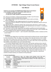
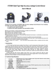
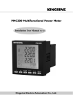
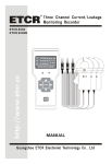
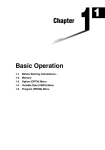
1
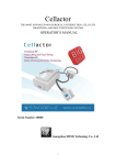
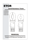
CONTENT
Warning....................................................................................................1
Ⅰ. Introduction....................................................................................3
Ⅱ. Model..............................................................................................4
Ⅲ. Electrical Symbols........................................................................5
Ⅳ.Technical Specification ..................................................................5
1.Base Conditions and Working Conditions ......................................5
2.General Specification......................................................................6
3.Intrinsic Error and Performance Indicators under Base Conditions7
Ⅴ.Instrument Structure.......................................................................8
Ⅵ. Method of Operation ....................................................................9
1.Switch On/Off.................................................................................9
2.Backlight Control............................................................................9
3.Date Lock/Release/Storage .............................................................9
4.Date Access/ Exit ............................................................................9
5.Deleting Date ..................................................................................9
6.Date Upload ..................................................................................10
7.Measurement.................................................................................10
Ⅶ.Battery Replacement ...................................................................13
Ⅷ.Other Descriptions and Notes ....................................................14
Ⅸ.Accessories...................................................................................16
Warning
Thank you for purchasing our ETCR4000A、ETCR4200A Intelligent Double
Clamp Digital Phase Volt-Ampere Meter (Full-automatic Double Clamp Digital
Phase Volt-Ampere Meter), in order to better use of this product, be sure to:
---- To read this user manual carefully.
---- Comply strictly with safety rules and precautions set out in this
manual.
u Pay special attention to safety under any circumstances while using the
instrument.
u Take note of the label text and symbols on the panel and back of the
instrument.
u Make sure that the instrument and accessories are intact and there’s no
damage to the instrument or test wire insulation layer, or bare and broken
wires before using it.
u Make sure that the function switch has been set up within the appropriate
range before the test.
u Can not be used to test voltage higher than 600V.
u It’s prohibited to use the instrument without the rear cover and battery
cover
in place.
u Make sure that the connection plug is closely inserted in the socket.
u Don’t use or replace batteries if the instrument is wet.
u Test is prohibited in flammable and dangerous places.
u The test line could only be pulled out from the instrument after being
removed
from the measured wire; don’t touch the plug jack by hand to avoid an
electric shock.
u Do not use the instrument in strong electromagnetic environment in order
to prevent the equipment from work improperly.
uDon't operating simultaneously two or more buttons, the operation will be
invalid.
u Stop using the meter in case of metal exposure due to a broken chassis or
fractured test line.
-1-
u Do not place or keep the device in hot and humid environment, or places
of
dew condensation or long time direct sunshine.
u The instrument and current clamp must be maintained regularly to keep
clean, corrosive solution and coarse materials can't be used to clean the
clamp.
u Keep the current clamp from any impact, especially the clamp joints.
u The instrument has an automatic shutdown function.
u Remove or replace the battery if the instrument is not used for a long time,
and take note of the battery polarity.
u Take note of the measurement range and application environment required
for the instrument.
u The operation, demolition, calibration and maintenance of the instrument
must be carried out by qualified personnel authorized to do so.
u The meter should be stopped from being used immediately and sealed if
danger is brought up in case of continued use; only a competent body can
be authorized to deal with it.
u The two COM ports of the instrument is internally short circuited, belong to
the same point.
u “
” in the manual is the safety warning sign, the contents of this manual
must be followed for safe operation.
u “
” and other safety signs, the contents of this manual must be followed
for safe operation.
-2-
Ⅰ. Introduction
ETCR4000A 、 ETCR4200A Intelligent Double Clamp Digital Phase
Volt-Ampere Meter (Full-automatic Double Clamp Digital Phase Volt-Ampere
Meter) is a well-developed full-automatic, multi-functional, digital, intelligent
meter specifically designed for field testing, which is a overall upgrade product
based on mechanical knob phase volt-ampere meter, can simplify operation
and reduce the possibility of misoperation, featuring high accuracy, high
stability, low power consumption, easiness to use and so on. It can directly
measure AC voltage and AC current without opening the measured circuit,
phases between three voltages, three currents and phase between the
voltage and current; in addition, the power factor and power of the circuit can
be indirectly measured, it can also be used to distinguish three-phase
sequence, transformer wiring group, inductive and capacitive circuits, test
second circuit and bus differential protection systems, read the phase
relationship between CTs of the differential protection, check the meter wiring
right, repair lines and equipment, etc.
ETCR4000A 、 ETCR4200A Intelligent Double Clamp Digital Phase
Volt-Ampere Meter has well designed shell mould made of newest material,
attach with shakeproof, skidproof, high insulation sheath, has a 240dots×
160dots LCD screen, all the test data display on the screen simultaneously,
vector diagram indication, and looks exquisite and comfortable. Meter
equipped with USB-RS232 interface, can store 500 sets of data, through the
system software upload stored data to the computer, implementing online
real-time monitoring and historical inquires, dynamic display. Can read, save,
report, print history data, etc. At the same time, its current clamps have two
kinds of specification optional, small mouth clamps are suitable for line
densely places, big round clamps are applicable to thick wire detection, to
meet the different place needs.
ETCR4000A 、 ETCR4200A Intelligent Double Clamp Digital Phase
-3-
Volt-Ampere Meter (Full-automatic Double Clamp Digital Phase Volt-Ampere
Meter) applies to electric power, petroleum chemical industry, metallurgy,
railway, and meteorology, industrial and mining enterprises, scientific research
institutions, measurement sector and so on. Especially for the electricity billing
system and relay protection system, and electricity measurement, electricity
check,
power inspection for power marketing department. Assembling, relay
protection, differential detection, start experiment, substation overhaul, or
power practical training, skills match for biotech department.
Ⅱ. Model
Model
Clamp Size
Note
ETCR 4000A
7.5mm×13mm
acuminate current clamp
ETCR 4200A
35mm×40m
-4-
round current clamp
Ⅲ. Electrical Symbols
Extremely dangerous! The operator must strictly abide by the
safety rules; otherwise there is risk of electric shock, resulting in
bodily injury or fatalities.
Dangerous! The operator must strictly abide by safety rules;
otherwise there is risk of electric shock, resulting in bodily injury
or fatalities.
Warning! Safety rules must be strictly abided by, otherwise
personal injury or equipment damage may be caused.
Alternate Current(AC)
Direct Current(DC)
Double Insulation
Ⅳ.Technical Specification
1.Base Conditions and Working Conditions
Ambient Temperature
Base
Condition
23℃±1℃
Working
Condition
-10℃~40℃
Ambient Humidity
40%~60%
<80%
----
Signal Waveform
sine wave
sine wave
β=0.01
Signal Frequency
Meter Working Volt
Current Amplitude in
Phase/Frequency/Phase
Sequence Test
Voltage Amplitude in
Phase / Frequency/ Phase
Sequence Test
Current Amplitude in
Power / Power Factor Test
Voltage Amplitude in
Power / Power Factor Test
External Electric Magnetic
Field
50HZ±1HZ
9V±0.1V
45HZ~65HZ
9V±1.5V
-------
1A±0.2A
2mA~20A
----
100V±20V
10V~600V
----
1A±0.2A
20mA~20A
----
100V±20V
10V~600V
----
Influence Quantity
Measured Wire Position
Remark
----
To be avoided
Measured wire at approximately the
geometric center of the clamp
-5-
2.General Specification
Function
Power
Consumption
Display Mode
Meter Size
Clamp Size
Measurement
Range
(automatic
shift)
Resolution
Sample Rate
Data Hold
Data Storage
RS232
Interface
Automatic
Simultaneous measurement of two AC voltage, current, phase
between voltage, phase between current, phase between
voltage and current, frequency, phase sequence, active power,
reactive power, apparent power, power factor, distinguish
transformer wiring group, inductive and capacitive circuits, test
second circuit and bus differential protection systems, read the
phase relationship between CTs of the differential protection,
check the meter wiring right, repair lines and equipment, etc.
DC9V alkaline batteries(1.5V AA×6)
About 70mA at most with enabled backlight, battery working
continuously for about 14 hours
About 40mA with disabled backlight, battery working
continuously for about 20 hours
LCD display, 240dots×160dots
Length, Width, Height:196mm×92mm×54mm
acuminate current clamp:7.5mm×13mm (optional)
round current clamp:35mm×40mm (optional)
AC Voltage:0.00 V~600V (automatic shift)
AC Current:0.0mA~20.0A (automatic shift)
Phase:0~360°
Frequency:45.00Hz~65.00Hz
Active Power:0.0W~12kW
Reactive Power:0.0W~12kVAR
Apparent Power:0.0W~12kVA
Power Factor:-1~+1
Voltage:AC 0.01V
Current:AC 0.1mA
Phase:0.1°
Frequency:0.01Hz
Active Power:0.1W
Reactive Power:0.1VAR
Apparent Power:0.1VA
Power Factor:0.001
About 2 times/second
Press HOLD key to keep data, "DH" symbol appears
1500 sets
USB-RS232 interface, download data to computer for analysis
and management
Automatic shutdown about 15 minutes later after launching to
-6-
Shutdown
Backlighting
Voltage
Detection
Weight
Test Line
Length
Current
Clamp Length
Working
Temperature
and Humidity
Storage
Temperature
and Humidity
Input
Impedence
Withstand
Voltage
Insulation
Structure
Safety
Specifications
reduce battery consumption
Suitable for dark place and nightly use
Low battery symbol “
" appears to remind the replacement
of battery when the battery voltage drops below 7.2V.
Main Unit about 550g(with battery),acuminate current clamp
about 170g×3, round current clamp about 185g×3, test line
about 250g
1.5m
2m×φ5mm
-10℃~40℃; below 80%Rh
-10℃~60℃; below 70%Rh
Testing voltage the input impendence is 2MΩ
Withstand 1000V/50Hz sine wave AC voltage for 1 minute
between the meter lines and shell; Withstand 500V/50Hz AC
voltage sine wave for 1 minute between the two voltage inputs
≥100MΩ between meter lines and shell or between the two
voltage inputs
Double insulation, with insulation vibration-proof sheath
IEC61010-1 CAT Ⅲ 600V, IEC61010-031, IEC61326, 2 class
of pollution
3.Intrinsic Error and Performance Indicators under Base Conditions
Category
Voltage
Current
Phase
Active Power
Reactive
Power
Apparent
Power
Frequency
Power Factor
Measurement
Range
AC 0.0V~600V
AC 0.0mA~20.0A
0.0°~360°
0.0W~12kW
Resolution
Intrinsic Error
0.01V
0.1mA
0.1°
0.1W
±(1.5%rdg+3dgt)
±(1.5%rdg+3dgt)
±1°
±(3%rdg+3dgt)
0.0VAR~12kVAR
0.1VAR
±(3%rdg+3dgt)
0.0VA~12kVA
0.1VA
±(3%rdg+3dgt)
45HZ~65HZ
-1~+1
0.01HZ
0.001
±(2%rdg+3dgt)
±0.03
Note: In working condition, phase error is ±3°(10mA~20A); ±6°(under 10mA).
-7-
Ⅴ.Instrument Structure
1. USB-RS232 interface
2. Insulation vibration-proof sheath
3. LCD display
4. Function keys area
5. Two voltage input interface
6. Current clamp input interface I2
7. Current clamp input interface I1
8. Current clamp output plug
9. Acuminate current clamp (optional)
10. Round current clamp (optional)
11. Voltage input test line
-8-
Ⅵ. Method of Operation
Check carefully before using the instrument whether
there’re damaged parts, no damage is allowed.
The instrument is prohibited from use in dangerous places.
Install the battery according to the manual.
Don't operating simultaneously two or more buttons, the
operation will be invalid.
1.Switch On/Off
Press ON button to switch on as shown on the LCD or press OFF to
switch off; Boot needs 5 seconds, to finish instrument internal automatic
calibration, the device powers off automatically about 15 minutes later
2.Backlight Control
Press
to control the backlight in dim places.
3.Date Lock/Release/Storage
In test model, press HOLD key to Lock currently displayed value and
display “HD “symbol. At the same time, this lock-values as a set of data
followed by auto-ID and store, display the group number such as“S:01”,
and then press HOLD key to cancel the lock, “HD” symbol disappeared,
can continue to measure. Loop operation, can store 500 sets of data. If
the memory is full, blinking display “FULL” symbol.
4.Date Access/ Exit
At the test state, press the MEMU key to access date inquiry form group
“R:01”, and display “RD” symbol. It is allowed to rapidly navigate to the
desired page number. Press “ △ ”key to increase the page number by
one, press ”▽” key to increase the page number by ten. Press “◁”key to
exit date inquiry, back to test state.
5.Deleting Date
At the date inquiry state, press “▷”key to access deleting data menu,
press“◁”or “▷” keys to move the cursor to “YES” or “NO” item. Press the
MEMU key with the cursor located at “YES” to delete the stored data.
-9-
Press the MEMU key with the cursor at “NO” to cancel the deletion and
return to the test state.
6.Date Upload
Connecting the meter and computer with USB-RS232 communication
line attached in package. Start up the meter, run software, choose history
access, then read, save, report, print history data, etc. The more data
storage, take the longer time to read it. Historical data can be saved in Txt
text or Excel format.
7.Measurement
High voltage, very dangerous!Only qualified personnel
after training could conduct operation on it. The operator
should obey safety regulations; Otherwise there will be
the danger of electric shock resulting in personal injury or
casualty.
Dangerous! Can not be used to test voltage higher than
600V. Otherwise there will be the danger of electric shock
resulting in personal injury or casualty.
Dangerous! Can not be used to test current higher than
20A. Otherwise it may damage the equipment.
Connecting wire strictly accordance with the manual
instructions, I1, I2 can't be confused.
After testing, must firstly move the test wire away form the
measured circuit, then pull out the test wire from meter.
Phase Test relationship of the instrument: U1U2、I1I2、
U1I1、U2I2, for every relationship the measured phase
shows the former signal ahead of the latter signal.
P1、Q1、S1、PF1 corresponding to the parameters of U1-I1;
P2、Q2、S2、PF2 corresponding to the parameters of U2-I2.
The red U1,U2 voltage jacks and the red dot marks or
arrow symbols on the clamp are dotted terminals.
In phase test the direction of the input current should be in
line with the arrow symbol on the clamp.
-10-
This instrument can test two AC voltage, current, phase between
voltage, phase between current, phase between voltage and current,
frequency, active power, reactive power, apparent power, power factor,
three-phase current vector sum, distinguish phase sequence, inductive,
capacitive circuit, etc.
Test connections as follow:
Single-phase test: connecting the measured wire L/N corresponding
to U1 red/COM black jack of the instrument, clamp L wire by current clamp
I1. To test the single line voltage, current, phase, frequency, power
parameters, etc. Also can connect U2 red, COM, I2 to test. As showed
below:
Three-phase four-wire test: connecting wires in two steps to test
three-phase four-wire voltage, current, phase, phase sequence, frequency,
power, power factor, etc. As showed below: (the two COM ports of the
instrument is internally short circuited, connect either of them to null line N)
Step 1
Three-phase
Meter
four-wire circuit
UA yellow
U1 red
UB green
U2 red
N black
COM black
Step 2
Three-phase
four-wire circuit
UB green
UC red
N black
-11-
Meter
U1 red
U2 red
COM black
Three-phase three-wire test: connecting the measured wire UA
yellow, UB green, UC red corresponding to U1 red, COM black, U2 red
jack of the instrument, clamp wire IA, IC respectively by current clamp I1, I2.
To test three-phase three-wire voltage, current, phase, phase sequence,
frequency, power, power factor, etc. As showed below: (the two COM ports
of the instrument is internally short circuited, connect either of them to null
line N)
-12-
During test, according to various phase relationship, inductive or
capacitive loads, phase sequence and polarity can be judged. If U1I1 phase
display within 0°~90°range, the measured load is perceptual; if within
270°~360°range, the measured load is capacitive. If the phase display
near 120° , it is positive phase sequence, and the same polarity; if near
120°or 300°, it is positive phase sequence, and the opposite polarity (may
be current clamp or wire reverse connection). Other conditions for negative
phase sequence (except default phase).
Ⅶ.Battery Replacement
Take note of the battery polarity, the polarity must be
properly installed, otherwise it causes damage to
the instruments
Batteries replacement is prohibited in hazardous
area
1.“
Must use qualified alkaline batteries(1.5V AA×6)
Old and new batteries are not allowed to mix in use.
”is displayed when the power voltage is lower than 7.8V~
8V,indicating that the battery should be replaced as following.
2.Press OFF to switch off
3.Use the cross screwdriver to loose a screw on the battery cover, open
the battery cover.
4.Remove the old batteries and replace a new battery, please take note
of the battery polarity.
5.Cover the battery cover, tighten the screws.
6.Press ON to switch on to check whether the battery is successfully
replaced, repeat step 2 if it doesn’t work.
7.Take out the batteries if the instrument will not be used for a long time.
-13-
Ⅷ.Other Descriptions and Notes
1.The special utility of current clamp
The two current clamps of each meter could only be used on this
instrument.
The current clamp should be prevented from any impact, the clamp
surface must be kept clean and could fully close for a reliable test.
2. The maintenance of current clamp
The dust on the surface of the current clamp should be removed
promptly after use; don’t use rough material or corrosive to clean the
clamp, which is best to be gently wiped clean with soft cloth and
lubricants (for example: WD-40 lubricants).
3. Preheat 3 to 5 minutes before the measurement to ensure the
measurement accuracy
4.The instrument should be used for secondary and low-voltage circuit
detection, and cannot be used to measure the current of high-voltage
lines to prevent electric shock.
5.Three-phase four-wire system (Phase of a balanced threephase load)
-14-
Phase
Relationship
Phase Value
Phase
Relationship
Phase Value
Ua-Ub
120°
Ia-Ib
120°
Ub-Uc
120°
Ib-Ic
120°
Uc-Ua
120°
Ic-Ia
120°
6.Three-phase three-wire (Phase of a balanced threephase load):
Phase
Relationship
Phase Value
Phase
Relationship
Phase Value
Uab-Ucb
300°
Ia-Ic
240°
Uab-Ia
30°
Ucb-Ic
330°
7.Three-phase four-wire vectogram and Three-phase three-wire
vectogram:
Three-phase four-wire vectogram
Three-phase three-wire vectogram
If the direction of current clamp or current line is
reversed there’s a phase value difference of 180 °, viz.
adding 180°to the standard value.
-15-
Ⅸ.Accessories
Main Unit
1 piece
Meter Box
1 piece
Current Clamp
3 pieces
Test Line
4 pieces(2 Yellow, 2 Black)
RS232 Data Line
1 piece
Disk
1 piece
Battery
6 pieces(Alkaline Dry Battery: 1.5V AA)
User Manual
1 copy
Guarantee Card
1 copy
Certification
1 copy
-16-
Manufactured by
ETCR Electronic Technology Company
Address: F-3F, No.4 Pengshang Zhifu Road, Jiahe, Baiyun
District, Guangzhou, Guangdong, China
Post Code: 510440
Tel: (86-20)62199556 62199553
Fax: (86-20)62199550
E-mail: [email protected]
Website: www.etcr.cc