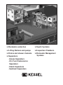
1
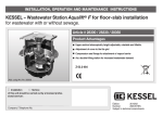
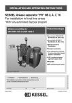
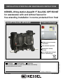
INSTALLATION, OPERATING AND MAINTENANCE INSTRUCTIONS
KESSEL-lifting station Aqualift 쏐F Duo/XXL SPF 550 KE
for wastewater with and without faeces for
free-standing installation in rooms protected from frost
Aqualift 쏐F Duo/XXL SPF 550 KE
Product advantages
Drilling surfaces for further
connections
Fully automatic operation
Maintenance-friendly
PE-tank
Installation
Commissioning
Subject to technical amend-
User-friendly menu navigation via a 6-line display
Instruction
The installation and service of this unit should be carried out by
a licensed professional servicer
Name/Sign
Edition 10/2010
Date
Town
Company - Telephone No.
ID-Nr. 206-830EN
1. Safety information
General safety precautions
During installation, operation, maintenance or repairs to the system, please observe the accident prevention regulations, the applicable DIN and VDE standards and guidelines, and also the regulations of
the local energy and supply companies.
The systems may not be operated in explosive areas
Electrical hazards
This system contains electrical voltages and controls rotating mechanical parts. Non-observation of
the operating instructions could lead to serious damage, injury or even fatal accidents.
The system must be securely disconnected from the mains supply before commencing any work on
it. The local master switch and the cut-outs must be turned off, i.e. switch the system to zero-potential and take precautions to ensure it cannot be switched on again. If only cut-outs are available, these
must be switched off and a sign attached to prevent third parties from switching the main fuse on again.
VDE 0100 applies to all electrical work on the system.
The switchgear and the level control are under voltage and may not be opened. Only electricians may
work on the electrical equipment. The term 'electrician' is defined in the VDE 0105.
Steps must be taken to ensure that the electrical cables and all other electrical system parts are in a
fully functional condition. If any parts are damaged, the system may not be operated and/or must be
immediately shut down.
!
Risk of burning fingers and hands
The driving engine may become very hot during operation
Risk of injury to fingers and hands
The pumps are equipped with a closed impeller. Therefore work on the pump may only be carried out
if the power supply has been disconnected and the rotating parts have stopped rotating.
Take care on sharp edges during maintenance or repair work.
Risk due to heavy weights
The lifting system models with one pump weigh around 45 kg, and with two pumps around 84 kg. The
systems may only be lifted or mounted by two persons with appropriate care wearing protective equipment (e.g. protective shoes).
The pumps may only be removed slowly or placed in the pump flange opening by two persons (if suitable precautions to prevent slipping have been taken).
2
1. Safety information
Health risk
The wastewater system transports wastewater that contains faeces; in turn this faeces may contain
harmful substances. Whenever working on the system, always ensure that there is no direct contact
between the wastewater and/or soiled system parts and your eyes, mouth or skin. In the event of direct contact, clean the affected part of your body thoroughly and disinfect if necessary. It is also possible that the atmosphere in the tank may be harmful.
Therefore before opening the cleaning aperture (or removing the pump) ensure that the respective room
is adequately ventilated or provide for (forced) ventilation during the opening process.
Noise pollution
When the pump is operated, a noise level is created that may be a nuisance depending on how the
pump is installed. If there are maximum noise level stipulations that need to be observed, appropriate
measures need to be taken. The sound damping set from KESSEL may also be helpful here.
Risk of explosion
The inside of the tank is considered to be explosive within the meaning of EN 12050 because the biological digestive process may create flammable gases (hydrogen sulphide, methane gas). Therefore,
when unscrewing the pump or the cleaning aperture lid or any other parts, ensure that the room is adequately ventilated or provide for (forced) ventilation during the opening process. Whilst the tank is open,
it is forbidden to smoke or carry out any other activities in the respective room that could cause the
gas to ignite (e.g. operation of electrical devices without encapsulated motors, metalworking etc.).
3
Table of contents
1. Safety information
...........................................................................................................Page
2
2. General
2.1
Application scope................................................................Page
5
2.2
Description of the system....................................................Page
5
3.1
Aqualift F Duo XXL ..............................................................Page
6
3.2
Information about safe use in explosive areas ................Page
7
4.1
Notes on the set-up location ...............................................Page
9
4.2
Connection of the pipes ......................................................Page
9
4.3
Level recording ....................................................................Page
10
5.1
General information .............................................................Page
11
5.2
Assembly of the switchgear ................................................Page
11
5.3
Installation, wiring................................................................Page
11
5.4
Checking the rotation direction of the pump ......................Page
11
5.5
Connection ..........................................................................Page
12
6.1
General information .............................................................Page
15
6.2
Pressure discharge pipes ....................................................Page
15
6.3
Description of the function ..................................................Page
15
6.4
Control unit operation..........................................................Page
16
7.1
Information about the pump................................................Page
19
7.2
Information about the backflow preventer ..........................Page
19
7.3
Information about the electrical switchgear ........................Page
20
8.1
General malfunctions .........................................................Page
21
8.2
Error messages ...................................................................Page
22
.............................................................................................Page
26
10. Warranty
...........................................................................................................Page
27
11. Declaration of conformity
...........................................................................................................Page
28
12. Handover record
...........................................................................................................Page
29
3. Technical data
4. Installation and assembly
5. Electrical connections
6. Commissioning
7. Inspection and maintenance
8. Malfunctions and
troubleshooting
9. Spare parts and accessories
4
2. General
2.1 Application scope
The lifting systems pump the wastewater (with and without
faeces) that is collected below the drain and local back-up
level into the sewers fully automatically in compliance with
the stipulations of EN 12056. They may only be used for
household wastewater, for example from detached homes
and apartment buildings, commercial operations, hotels and
restaurants, shops, hospitals, schools or other similar cases.
If the incoming flow to the lifting system may not be interrupted during normal operation, the lifting system also
needs to be equipped with a second pumping device with
the same output level that can switch on automatically if required (double instead of single system).
The KESSEL Aqualift® F lifting system is designed for freestanding installation in frost-protected rooms. The associated switchgear needs to be installed in a dry room protected from flooding and frost. The pressure lines must be designed to be at least DN 80, the ventilation lines at least DN
50. Abrasive media must be kept away from the pump impeller.
The systems are suitable for permanent wastewater temperatures of up to 35°C. Brief (up to 10 minutes) incoming temperatures of maximum 60°C are allowed.
2.2 Description of the Aqualift F Duo XXL system
1993 mm
➅
➁
DN 150
➀
1092 mm
➅
391 mm
➄
➆
➆
➃
➇
1923 mm
➀ Intake line DN 150
➁ Pressure connection DN 100
➂ Ventilation DN 100
➃ Two wastewater pumps each with a 5 m connection line
➄ Sump made of polyethylene
5
➇
➅ Cleaning aperture
➆ Blocking device
➇ Check valve
➃
➂
3. Technical data
3.1 Aqualift F Duo XXL
Models:
• Aqualift F Duo XXL (double system) 3,3 kW with pressure discharge DN 100,
• Aqualift F Duo XXL (double system) 4,2 kW with pressure discharge DN 100,
• Aqualift F Duo XXL (double system) 5,6 kW with pressure discharge DN 100
Max. Förderhöhe H (m)
Pumping capacity diagram Aqualift ® F Duo XXL
22
20
18
16
14
12
10
8
6
4
2
0
400 V 3,3 kW
400 V 4,0 kW
400 V 5,6 kW
Q min nach DIN EN 12056-4 für DN 100
0
10
30
20
Max. Fördermenge Q (m³/h)
0
5
Max. Fördermenge Q (l/s)
40
10
Typ
Rated output (P2)
Power input (P1)
Operating voltage
Rated frequency
Rated current
Connection line
Temperature of pump. mat.
Weight (pump)
Protection class
Operating type
Sound level
total weight
50
60
15
70
80
20
SPF 260 KE
2,6 kW
3,3 kW
400 V DS
50 Hz
6,4 A
5 m Length, 7 x 1,5 mm
40 °C
30 kg
IP 68 (24 h /3 mWs)
S2
30 Min.
< 80 db
2
SPF 400 KE
3,5 kW
4,2 kW
400 V DS
50 Hz
7,9 A
5 m Length, 7 x 1,5 mm
40 °C
30 kg
IP 68 (24 h /3 mWs)
S2
50 Min.
< 80 db
2
ca. 200 kg
6
SPF 550 KE
4,8 kW
5,6 kW
400 V DS
50 Hz
10,2 A
5 mLength 7 x 1,5 mm
40 °C
31 kg
IP 68 (24 h /3 mWs)
S2
30 Min.
< 80 db
2
3. Technical data
3.2 Information about safe use in explosive areas
Proper use
The pump control system serves to operate a dual-pump
faeces lifting system. A pressure switch or another type
of switch is used to record the level of faeces.
The operating equipment must be installed outside the
explosive area.
Classification::
II (1) GD [EEx ia] IIC
(Group II, Category (1)G, associated operating equipment for gas atmosphere)
The specifications of the standard EN 50014:1997 + A1
- A2, EN 50020:2002 are satisfied.
EC-type examination certificate of the Zener barriers
BAS 01 ATEX 7217
Identification
Type: double system
Level circuit in ignition protection type Intrinsic safety
EEx ia IIC
(terminals OFF, ON1, ON2, ALARM
Zener barriers MTL 7789+
Maximum values
Uo = 28 V
Io = 93 mA
Ro= 300
Po = 0,33 W
Co = 0,083 µF
Lo = 16 mH
Lo / Ro= 106 µH /
Installation / assembly instructions
• Observe the respective national regulations and provisions
• The respective installation provisions need to be observed
• Also observe the installation and assembly instructions of the non-ATEX relevant operating instructions
Special conditions for safe operation
none
II (1) G [EEx ia] IIC CE1180 Ta = -20°C .. + 60°C
Maintenance / servicing
Operating instructions
Installation / commissioning
The devices may only be built, connected and commissioned by qualified persons. The qualified staff must
have expertise regarding ignition protection types, operating equipment regulations and ordinances in explosive areas.
Check if the classification (see above "Identification"
and identification on the device) is suitable for the case
at hand.
• Allowed ambient temperature range at the place of use:
0 ... + 50°C
7
• When the lid is removed, the stated protection class
(tightness) is reduced. Check first whether there is a risk
associated with a high level of damp, splashwater or
any other soiling. In this case the control system should
be disconnected from the power supply first. In all
cases, steps should be taken to prevent water, fluids or
general dirt from penetrating. Only an electrician may
open the lid.
• After opening/operation, the lid of the casing must be
closed again correctly to guarantee the protection class
(tightness).
• The device may not be modified. Repair work is not
possible. In the event of a malfunction, please contact
the manufacturer.
• If necessary you can order data sheets, EC test examination test certificates, operating instructions and
EC Declarations of Conformity from the manufacturer
(see cover sheet).
3. Technical data
3.3 Electrical switchgear
3.3.1 General technical data
3.3.4 Outputs
Ambient conditions
Approved temperature range:
Approved humidity:
Maximum operating height:
0 to 50 °C
10 to 80 %
Not condensing
2000 m above sea level
Power input
max. approx. 5 VA for simple system
(Electronic without motor)
Protection class
class 1
Relay "Malfunction"
Two-way contact; opener, middle contact, closer respectively max. 42 Vac/dc 0.5A for relay “Malfunction” and “Warning”; separate fuse for external voltage.
Caution: Even when the master switch is switched off there
is still external voltage on.
Relay "Warning"
Two-way contact; opener, middle contact, closer respectively max. 42 Vac/dc 0.5A
Protection type
IP 30 if fitted correctly.
Main supply
Connect a separate fuse for the external voltage supply
3.3.2 Power supply
Motor 1/2 (double system)
Motor 1/2
PE
mains connection
(Spring terminal on circuit board)
Motor 1/2
U
Terminal 1/6
Motor 1/2
V
Terminal 2/7
Motor 1/2
W
Terminal 3/8
Main connection
PE/N/L1/L2/L3 acc. to identification on the terminal block
and master switch
Operating voltage
400 / 230 V 3~ 50 Hz ± 10% three-phase current (L1=230V
AC / 50Hz±10% to supply the electronics power units)
Required fuse
max. 25 A C phase (to be provided for on installation side)
Leakage current circuit breaker with 30 mA rated residual
current
3.3.3 Inputs
- Every pump has TF1
- TF2 bridged (do not remove bridge)
- Level inputs respective
approx. 24 Vda < 5 mA (without ATEX)
- Level inputs via Zener barriers (with ATEX)
8
4. Installation and assembly
The delivery includes the following parts (see section 2.2):
- Sump with all mounted parts
- Electrical switchgear
- Accessories
IMPORTANT:
The electrical switchgear must be stored in a frost-free
and dry place. If the system is not connected electrically during installation, the switchgear must be stored properly in the meantime.
CAUTION:
Risk due to heavy weights. The lifting systems each weigh
approx. 45 kg (single systems) and approx. 84 kg (double system). The parts may only be lifted and mounted taking
great care and whilst wearing the correct equipment. If the
system is dropped irreparable damage may be caused to
the system parts (e.g. pump) or the entire system. This damage is not covered by the warranty.
INSTALLATION SITE:
The KESSEL Aqualift® F lifting system is designed for
free-standing installation in frost-protected rooms. The
associated switchgear needs to be installed in a dry room
protected from flooding and frost..
4.1 Assembly of the sumps
To allow assembly, maintenance and servicing work to be
carried out on the lifting systems easily, they always need
to be installed so that the lifting system can be easily accessed and that there is at least a free space of 60 cm around the system as stipulated in EN 12056 (all round and on
top).
The system must installed horizontally in an appropriate position in the room on sound absorbing material (available
from KESSEL as an accessory). The lifting system must be
connected to the ground using the supplied brackets, screws and wall plugs to prevent it from slipping or turning.
4.2 2 Connection of the pipes
All pipes must be installed so that they can empty on their
own. All pipe connections must be designed to be flexible
and sound-damping.
A standard plastic sleeve can be pushed over the pipes
Connections to the drilling surfaces on the side (for supply line
or manual diaphragm pump) by drilling with the hole saw*, insertion of the matching greased seal* and pushing over a plastic
pipe (see Fig. A)
Pipe opening seal
Drilled opening
Pipe connection
Tank lifting system
Abb. A
* KESSEL accessory
9
4. Installation and assembly
l Inlet pipe
4.3. Recording the level
The inlet pipe must be laid at a gradient to the KESSEL lifting station in accordance with EN 12056 and be routed as
straight as possible. Connection is with DN 150
l Ventilation
The ventilation pipe sets up pressure compensation to the
fresh air for the air flowing into or out of the system during
emptying or filling. Connection is designed with DN 100 (DA
110 mm) and must be routed to above the roof to avoid
odour pollution.
l Pressure line
Setting the float switch
The float switches are fitted and set in the factory. Changing
the settings can lead to malfunctions.
Four float switches are required to switch this system (OFF
- ON1 - ON2 - ALARM). The alarm level lies approximately
at the same height as the lower edge of the supply pipe.
If another switching level is required, the floats need to be
set accordingly. However ensure that the alarm float does
not switch above the supply pipe and that the OFF float prevents air from being sucked in. Complete flooding of the
pump is advisable.
The pressure line used to drain the dirty water into the sewer
system must be connected directly to the respective pressure line connection. In compliance with the specifications
of EN 12056, the pressure line must be laid above the local
back-up level and should be connected to a vented mains
pipe or distributing main.
For acoustic decoupling purposes and to avoid the transfer
of forces, the supplied rubber braided hose of approx. 4 m
in length always needs to be pushed over the pressure pipes
at the pressure connection and fixed via a hose clip. The
rubber braided hose connection is not a longitudinal forcefit connection. This must be attached on site e.g. using holders.
The pressure line must be fitted (see below) so that the no
forces are exerted on to the system and that there is no direct contact with the building (structure-borne noise). No
other drainage objects may be attached to the pressure line.
The tightness and strength must be guaranteed even under
pressure.
This should be tested when the system is commissioned.
To avoid pressure shocks, the pressure line should not be
connected too tightly to the building. If cast iron or steel
pressure pipes with low damping properties are used, a
pressure shock damper must be fitted into the pressure line
if the pumping height exceeds 5 m.
A gate valve needs to be installed in the pressure line on site
as stipulated in EN 12056. We recommend using the
blocking devices for Mono-systems (Art.No. 28683) and for
Duo-systems (Art.No. 28694) from the KESSEL accessories
range.
Check valves to prevent pressure shocks for installation in
the pressure line are available as accessories:
DN 80 check valve from GG (Art. No.: 206-199
DN 100 check valve from GG (Art.No .206-198)
Backflow preventer (Art.No. 206-200)
10
5. Electrical connections
5.2 Assembly of the switchgear
CAUTION:
Only qualified electricians may carry out the work described below to the electrical equipment. Before commencing any work on the switchgear, the pump or the level
control, the master switch and cut-outs must be switched
off and secured against being reconnected.
5.1 General information
The strain must be taken from all connected cables by
means of screw connections.
Any screw connections that are not used must always be
closed correctly.
IMPORTANT:
After the end of the installation work, all the cables
connected to the electrical switchgear need to be affixed
by suitable means (e.g. cable ties) so that in the 1-error
case or if a connection comes undone this does not pose
a hazard.
Please observe the national and local safety regulations.
Noncompliance could lead to injury. Also this will result in a
limitation of liability and warranty exclusion. After the completion of the work, the cover plate and the transparent casing lid must be reattached correctly (contact and splashwater protection).
11
Screw the casing lid tight with a max. force of 1 Nm. Install
the supplied switchgear in a frost-free, dry room that is protected against floods and well ventilated. The switchgear is
designed for wall mounting on a firm surface. To prevent excessive inner temperatures, ensure there is adequate air circulation. The unit is assembled using 4 screws (diameter 6
mm) in the corners of the casing. The attachment holes can
be accessed by opening and folding back the upper lid or
removing the lower lid.
5.3 IInstallation, wiring
The cables pre-mounted to the pumps and the pressure
level switch have a standard length of 5 m. The pump cables may only be extended using a VDE-conform connection.
5.4 Checks
- the setting of the motor circuit breaker
The motor circuit breaker need to be set to the values for
the rated current of the associated pumps as stated in section 3.
5. Electrical connections
5.5 Circuit diagram XXL - SPF 550 KE, Atex
12
5. Electrical connections
13
5. Electrical connections
Work to be carried out
Work to be carried out
DOUBLE SYSTEM - OBSERVE SAFETY INFORMATION!
Description
Battery connection
• Both batteries (2 x 9V-Block) must be connected to the circuit board. .
Mains connection
• Mains power cable L1 / L2 / L3 / N / PE to terminal left (PE, N, L1, L2, L3).
• N and PE always need to be connected.
• The stipulated pre-fuses on the installation side may not exceed 25 A C per phase.
• If connected wrongly, the control system nay become damaged or be destroyed.
Motor supply line
• The motor supply lines 2 x U/V/W need to be connected logically to the terminals 1,2,3
(Pump 1, left) or 6,7,8 (Pump 2, right). The rotational direction of the motors needs to
be observed.
• The temperature sensors (strand 5 and 6) and the protective earth PE must be connected to the respective pump clamping block.
Recording the level
The end of the cables of the float switch are connected to the terminals 11-18 as stated on the circuit diagram (see page 12)..
Outlets
• The "Malfunction" and "Warning" messages are each sent via a relay (two-way
contact) without "Malfunction" and "Warning
• Suppressor. Interference from inductive loads need to be suppressed externally. The
idle state (current-free) of the relay is printed onto the circuit board. It means that the
"Malfunction" and "Warning" message is switched on.
• 42 V dc / 0.5 A
14
6. Commissioning
6.1 General information
of these instructions.
Commissioning
The commissioning process must be carried out by a qualified person. The availability of this person is the responsibility of the direct supplier of the wastewater lifting system. A test
run with water lasting at least two switching cycles is required for the commissioning process. During the test run, steps
should be taken to prevent the system running dry. The following need to be tested before, during and after the test run:
a) the electrical cut-out of the wastewater lifting system according to the IEC regulations and local regulations;
b) the rotational direction of the motor;
c) the valves (activation, open position, tightness);
d) the switching and setting of the switching levels in the
sump, if not already set by the manufacturer;
e) tightness of the system, fittings and lines;
f) testing of the operating voltage and frequency;
g) function test of the backflow preventers;
h) alarm relay;
i) attachment of the pressure line;
j) motor circuit breaker; tested by temporarily unscrewing two
cut-outs (two-phase run);
k) oil level (if there is an oil chamber);
l) control lamps and counters;
m) function test of the manual pump if one has been installed.
The commissioning process must be documented in writing
during which important data, such as e.g. the setting of the
motor circuit breaker and the data of the operating hour counter, are recorded. The commissioning process may only be
carried out by qualified persons. The standard DIN 1986, Part
3 must be observed when commissioning lifting systems.
IMPORTANT
Check all screw connections are tight.
6.2 Pressure discharge pipes
DAs standard, the pressure discharge pipes of the lifting system are equipped with a check valve and backflow preventer for each pipe. The backflow preventer must always
be operational (see Fig. 1).
The flap (dotted line) is only opened by the flow of the pump.
Abb. 1
6.3 Description of the function
Caution
Before starting the commissioning process, the intake lines
and the pump need to be cleared of solids such as metal,
sand etc.
Before starting the commissioning process, the pump must
be filled with the pumped liquid up to the level of the venting borehole in the pump casing.
The pump may not suction in any air!
After the whole system and all the extra parts, pipes and electrical connections have been installed completely and
correctly, the system can be started. All fitted gate valves
must be open.
Before commissioning please ensure that the rated voltage
and current type stipulated for the system correspond to the
rated voltage and current type on site.
Before starting the commissioning process, check the installation/cables again carefully. Is the protective earth effective? Have the relevant standards / guidelines been observed, in particular with regard to the explosive area? Do
not start the system if there is any visible damage to the
motor, the switchgear or the cables.
Please always observe the safety instructions in Chapter 1
15
The system is operational when the POWER-LED shines
and if no malfunction (ALARM-LED) are displayed. As the
level of (dirty) water in the tank rises, the float recognises the
ON level and the pump is switched on. When the pump operates, the level of water in the tank drops so that the OFF
level is undercut again. After the end of the after-running period, the pump is switched off. The float symbols in the display show when the respective levels have been reached.
If the current running time of the pump exceeds the configured value of the maximum limit running time, the pump is
switched off. At the same time a malfunction is indicated by
the orange LED and the relay output "Malfunction". The
malfunction (LED and relay) remains saved until the "Alarm"
key is pressed.
The pump(s) can be switched on by pressing the test key
twice.
6. Commissioning
6.4 Operating the switchgear
Display/display field
Aqualift F Duo 400V
Confirmation key/OK-key
Return key/ESC-key
Pumpe I
Pump I
ESC
Movement keys/direction keys
OK
Pumpe II
Pump II
Power-LED to indicate the system is operational
Control lamp for alarms
Activate the pump manually by pressing
twice
Comment:
If the lid is lifted, the master switch must be
switched off regardless of what the system is
currently doing
.
The first time the system is initialised the control device asks for four basic settings. The following appears in the control device display asking for
1. the user language
2. the date and time
3. sensor configuration
4. output parameter
Use the movement keys / direction keys to
mark the required setting and then press the
confirmation key to save the selected setting in
the system memory. As soon as the 4 presettings have been made, the control device loads
the program memory and enters the operating
mode.
The system is now operational.
16
6. Commissioning
Menu navigation
The switchgear menu navigation is divided into the system information and also three separate main menu
items. The background lighting is activated by pressing
the operating key once.
OK-key
ESC-key:
▲:
▼
Jumps to the next lower level
Jumps to the next higher level
Navigation within a level
The acoustic signal can be acknowledged
by pressing once.
If the error has been rectified, the alarm
key can be pressed again to acknowledge
the optical error.
If there is a mains power failure, the system is not operational. The switchgear goes into stand-by mode (battery
mode). This is signalised by an acoustic and optical alarm
The acoustic alarm can be acknowledged by pressing the
alarm key. The stand-by mode is maintained for at least
72 hours. If the battery is discharged, the device automatically switches off. The switchgear can be switched
off manually by pressing the alarm key (for more than 5
sec) in stand-by mode.
When the mains power comes on again, the device initialises automatically and is operational again.
Note:
Some menus are protected by a password to ensure the
system is used properly.
If the error has not been rectified, pressing the alarm key
again will retrigger the acoustic alarm.
6.4.1 System menu
0.
Systeminfo
Leistungsgröße
Sensorkonfiguration
Datum
Uhrzeit
Füllstandsanzeige
Information
Informationen
Maintenance
Wartung
Fehler/Ereignisse
Positions
Einstellungen
Beispiel:
Display the hierarchy level incl.
>
Numbering
Pump:
Floater:
System type
Control type
Füllstand:
Date / time
Current filling level
17
6. Commissioning
Operating hours
Displays all running times of the system.
6.4.2 Information menu
Information
Systeminfo
Informationen
Systeminfo
Systeminfo Informationen
Uhrzeit: 00:00:00
Uhrzeit: 00:00:00
1: Ein / Aus
Schwimmer
1: Ein / Aus
Schwimmer
TX: (Phase
bis T24)
TX:T1(Phase
T1 bis T24)
TX1: (Zeit:TX1:
00:00:00)
(Zeit: 00:00:00)
Attendend
time
Betriebsstunden
B
Wartung
Maintenance
Wartung
Events/Errors
Ereignisse / Fehler
Positions
Einstellungen
Einstellungen
Command
type
Steuerungstyp
Maintenance
Date
Wartungstermin
Water
level
Wasserhöhe
Parameter
Parameter
G
Events / errors
Chronological error and event display (see also Chapter 10 "Malfunctions and troubleshooting")
All modifications to the settings are saved here.
Control type
Displays the output parameters and the sensor configuration incl. combinations:
• pressure sensor (pressure)
• alarm
• compressor (comp.)
• float
Maintenance date
Shows the next and the last maintenance date.
Note: Dates are only available if they have been filed in
the 'Settings' menu by the servicing partner.
Current measured values
Displays the mains voltage, current, battery voltage
and filling level.
Parameter
Displays all the system control parameter settings:
Mains-ON delay, height of the dynamic pressure bell,
switch-on lock, measuring range, ON1 level.
6.4.3 Maintenance menu
Systeminfo
Manual operation
In manual mode, the automatic mode is deactivated.
Information
Informationen
man.
operation
Handbetrieb
Maintenance
Wartung
SDS
Testbetrieb
Positions
Einstellungen
Maintenance
Date
Wartungstermin
Self-diagnosis system (SDS)
System test similar to initialisation.
Maintenance date
The next maintenance date is entered by the servicing
partner.
6.4.4 Settings menu
Parameter
Systeminfo
Information
Informationen
Maintenance
Wartung
Parameter
storage
Parameterspeicher
Date/time
Datum / Uhrzeit
Only authorised maintenance staff may change the settings. To do this, the KESSEL Customer Service must be contacted for the
password.
Sensor
storage
Schwimmer
Positions
Einstellungen
Communication
Drucksensor
Nominal
size
HW Modul
Language
UW Modul
Reset
Drucküberwachung
K
18
7. Inspection and maintenance
The system must be inspected once a month by the operator with regard to serviceability and leaks by observing a
switching cycle.
CAUTION:
Always disconnect the system from the mains supply before servicing! Observe the safety instructions!
7.2 Information about the backflow preventer
The backflow preventer can be used to completely empty
the pressure line by manually lifting the check valve of the
lifting system. To do this, turn the flap opener with a size 8
(15 mm) wrench and hold (see Fig. 2) until the pressure line
is empty. After this, the flap opener must be returned to its
original position or the marked operating setting (see Fig. 3).
Only authorised qualified persons may carry out the inspection and maintenance tasks described below.
Repairs may only be carried out by the manufacturer.
When servicing lifting systems, the DIN 1986, Part 3 must
be observed. Maintenance must be carried out regularly by
authorised qualified persons..
IMPORTANT:
All screws may only be tightened with a maximum
force of 3 N
The following tasks must be carried out:
• Visual inspection of the entire system, the pumps and the
fittings
• Thorough cleaning of the entire system and the pump
• Inspection of the entire system and pump casing for external damage and visible wear
• Inspection of the pump to ensure it runs smoothly and for
wear and deposits
• Inspection of the connection lines for mechanical damage
and wear
• Inspection of the seal connections for leaks; in the event
of recognisable wear, exchange the seals (e.g. O-ring)
• Check the insulation on the pump motor
• If necessary test the function of the blocking device
• The check valve must be replaced after 2 years service.
Ill. 2
7.1 Information about the pump
The pump should be inspected at regular intervals. When
the operating noises become louder or there are vibrations
in the pipe system, the pump casing and impeller need to
be checked for any ingrained dirt or wear.
To do this, unscrew the four attachment screws on the motor
unit and remove from the pump casing.
When inspecting the pump casing, note that the venting borehole must remain open under all operating conditions.
19
Ill. 3
Note:
When the screw connections on the lower and upper flange of the valve casing are unscrewed, the entire valve casing can be removed for cleaning and maintenance purposes. Of course before this happens the pressure line must
be blocked and drained.
7. Inspection and maintenance
7.3 Information about the electrical switchgear
• The battery is a wear part and should be checked once a year
and exchanged if necessary. Ensure that the replaced battery
is disposed of correctly in an environmentally compatible
manner. It may only be replaced with a battery of the same
type.
• The contactor is a wear part and should be checked once a
year and exchanged if necessary. Ensure that the replaced
battery is disposed of correctly in an environmentally compatible manner. It ay only be replaced with a battery of the same
type.
• After the maintenance work the switchgear lid must be closed again correctly (contact protection!).
• Repairs may only be carried out by the manufacturer.
20
8. Malfunctions and troubleshooting
The following tests and troubleshooting steps may only be undertaken by authorised and qualified persons. If in doubt,
please contact your specialist dealer (see stamp on the cover sheet) who installed the system initially.
8.1 General malfunctions
1
2
Malfunction
Pumps do not start.
Pumps are running,
alarm level is reached /
is displayed.
Caution
Troubleshooting
Motor circuit breaker has triggered, motor is blocked
Remove the pump; remove the blockage (foreign body) in the impeller or casing
Motor is labouring
1 or 2 phases have no current
Control system fails due to heavy
fluctuations of the mains supply
Maintenance / repair by the Customer Service
Check the cut-outs and electrical cables
Retrofit a battery in the switchgear and inform
the power supplier.
Wrong revolving field
2 Exchange the phases of the power supply
System is overloaded.
Check if there is a brief excess of wastewater;
if necessary refrain from using the drain points
temporarily or if possible, drain the wastewater through a different channel
Pump output too low
• Remove the foreign body from the impeller or
casing
• Remove the foreign body from the pressure
fitting or the pressure pipe
• Pumps are worn, arrange for them to be
exchanged
• Lifting system wrongly designed, clarify with
the KESSEL Customer Service
backflow preventer not in operating position
3
4
Wastewater does not drain, System not switched on
backlog in the lowest drain
Electrical power cable to the switpoints
chgear without current
System sudden becomes loud
Bring the backflow preventer into the operating position
Switch on master switch.
Check cut-out. Check power supply
Level control is not working correctly
Check for soiling, check the switch points and
function of the level control
Supply line to the system is blocked
Clean the supply line
Intake valve to the system (if there is
one) is not open or not compl. opened
Wastewater temperature is too
high over a longer period of time
(15 min.); this limits the suction capacity of the system
Completely open the intake valve
Reduce the temperature of the wastewater
Check the pump parts and replace if necessary
Foreign body has damaged parts of Check the pump parts and replace if necessary
the pump
Foreign body inside the pump
21
8. Malfunctions and troubleshooting
Störung
5
Ursache
Abhilfemaßnahme
Leaks in the lifting system
Remove foreign body; check pump for damage and replace if necessary
Foul smell
Pump leaks
Check the pump; if necessary arrange for repair or exchange by the Customer Service
Motor(s) too hot, overloaded
Check the motor and pump run smoothly,
check the system for switching errors (in particular the motor circuit breaker)
Pungent smell
Frequent switching on and off of the system
due to high supply quantities, clarify with the
KESSEL Customer Service
Contactor too hot due to switching malfunctions
7
8
9
System runs too frequently, Supply quantity is too high due to
external water etc.
switches on without reason
Check system for switching errors.
Determine the cause and the remedy
The check valve is defective, wastewater runs from the pressure
pipe back into the system
Check the check valve (integrated in the pressure discharge pipes of every pump), clean and
exchange any damaged parts
System does not switch off or Foam is created in the system
has a variety of malfunctions
Tanks or the pumps have become
covered in grease due to high
quantity of grease in the supply
material
Reduce the use of washing detergent or washing-up liquid
Clean the entire system, check incoming grease levels
Ventilation of the level control is
blocked
Check if there is a kink in the air hose between
the switchgear and level control and if it is installed correctly (even gradient); if necessary
correct or exchange
Level control is soiled; switch
points set wrongly or illogically
Dismantle the level control, clean the immersion tube, check the pressure control; check the
levels; setting values for the levels
Revolving field wrong
Exchange power cores (malfunction message
on the switchgear)
Rotational direction of the pumps
is wrong
Check the pump cores are connected correctly
Pumped quantity is too low
8.2 Error messages
Every malfunction is shown on the display. If several errors occur at the same time, these are shown one after another and
can be viewed by scrolling down the display.
22
8. Malfunctions and troubleshooting
Error messages / troubleshooting
= lit up
= off l =slowing flashing
❍ = fast flashing
Battery error
- acknowledge alarm and alarm key
- check if the battery is connected
- exchange discharged battery
- the charging status of the batteries can be tested in menu 1.5.3
(measuring the battery voltage)
- after acknowledging the signal tone, press the alarm key again
--> switchgear continues to work without the batteries
--> no protective function in the event of a mains power failure
Mains failure (battery mode)
- Check if the mains failure has just affected the room or the entire building
- Check the cut-outs / check the error current circuit breaker
- Check if the mains supply cable is defective
- Check the micro fuse in the switchgear
(only use a fuse with the same rated value and tripping characteristics).
Motor error
Cause: TF1, TF2, motor circuit breaker
Remedy:
- If display shows “Motor circuit breaker 1/2”
--> check the motor circuit breaker 1/2
Duo Pumpe 1
- If display shows “TF1a / TF2a”
--> the lower winding temperature switch has triggered
--> resets automatically when the motor cools down
Error message must be acknowledged with the alarm key.
- If display shows “TF1b / TF2b”
--> for lifting systems, bridge TF2 defective/not installed
Duo Pumpe 2
Exchange/install bridge
23
8. Malfunctions and troubleshooting
Limit running time error / limit running count error
- Limit running count error: Pump is activated more than 20 times in 3 min
--> Check the air pipe between the immersion tube/immersion bell and switchgear
for water inclusions
--> Check if the immersion tube/immersion bell is blocked
--> Check intake, check pump capacity
Duo Pumpe 1
- Limit running time error: Pump runs for longer than 240 min without stopping
--> Check the air pipe between the immersion tube/immersion bell and switchgear
for water inclusions
--> Check if the immersion tube/immersion bell is blocked
--> Check intake, check pump capacity
Duo Pumpe 2
Sensor error (only for XXL-systems)
- Level error:
A float indicates a level although no float below has triggered (wrong sequence float)
--> Check the float cable of the float below
--> Check the function of the float in the tank (lift)
--> The pump(s) is/are switched on.
The switchgear works with the recognised level.
Duo Pumpe 1/2
Revolving field / phase errors
- Revolving field error:
Wrong revolving field when connected to mains Switchgear
--> exchange 2 phases
- Phase error:
Phase L1 or L2, L3 do not exist
--> Check connection to switchgear, power cable, cut-outs,
Duo Pumpe 1/2
Check error current circuit breaker
--> If L1 fails, the revolving field direction cannot be recognised.
--> If L1 fails, the switchgear goes into battery mode
--> In the case of revolving field errors, the pumps are not switched on in manual or
automatic mode
24
8. Malfunctions and troubleshooting
Relay switching cycles
Main contactor has exceeded 100,000 switching cycles
--> can be acknowledged, main contactor does another 1000 switching cycles before
a new message is sent
--> Exchange the contactor --> Contact the Customer Service
--> After 100000 switching cycles the relay switching cycle error is repeated after
every further 1000 cycles
Duo Pumpe 1
Duo Pumpe 1
Relay error
Main contactor no longer switches off
--> Disconnect the switchgear from the mains
--> Exchange the contactor --> Contact the Customer Service
Duo Pumpe 1
Duo Pumpe 2
Alarm level exceeded
Alarm level is achieved by the water level
--> Alarm turns off automatically if the alarm level has been undercut again
--> LED only turns off after it has been acknowledged manually
--> Check intake
--> Check level recording and switch points
Duo Pumpe 1
25
9. Spare parts and accessories
Accessories
Designation
Order-Nr.
Manual diaphragm pump
28680
Stopcock for manual diaphragm pump
28681
Elastic hose connection with 2 hose clips
Flange-hose connection
DN 40
28660
DN 70
28661
DN 100
28663
DN 80
28655
DN 150
28658
Gate valve made of plastic for unpressurised installation DN 100
28698
DN 150
28699
DN 50
850114
DN 70
850116
DN 100
850117
DN 125
850118
DN 150
850119
Seal for pipe opening
Hole saw DN 50 - DN 150
50100
Battery (1 unit)
Blocking device
197-081
DN 100
28683
Compressor set for air bubbling
28048
Air filter for compressor (28048)
363-140
Motorschutzschalter 9-14 Amp.
363-186
Motor circuit breaker 6.3-10 Amp.
363-151
Level sensor
363-138
Float for XXL-system
185-043
Motor complete 5.6 kW for XXL-system
245-406
Switchgear for XXL-system (ATEX)
363-196
Switchgear for XXL-system
363-197
See also KESSEL Catalogue
26
10. Warranty
1. In the case that a KESSEL product is defective, KESSEL has
the option of repairing or replacing the product. If the product
remains defective after the second attempt to repair or replace the product or it is economically unfeasible to repair or
replace the product, the customer has the right to cancel the
order / contract or reduce payment accordingly. KESSEL
must be notified immediately in writing of defects in a product. In the case that the defect is not visible or difficult to
detect, KESSEL must be notified immediately in writing of the
defect as soon as it is discovered. If the product is repaired
or replaced, the newly repaired or replaced product shall receive a new warranty identical to that which the original (defective) product was granted. The term defective product refers only to the product or part needing repair or replacement
and not necessarily to the entire product or unit. KESSEL
products are warranted for a period of 24 month. This warranty period begins on the day the product is shipped form
KESSEL to its customer. The warranty only applies to newly
manufactured products. Additional information can be found
in section 377 of the HGB.
27
In addition to the standard warranty, KESSEL offers an additional 20 year warranty on the polymer bodies of class I / II
fuel separators, grease separators, inspection chambers,
wastewater treatment systems and rainwater storage tanks.
This additional warranty applies to the watertightness, usability and structural soundness of the product.
A requirement of this additional warranty is that the product
is properly installed and operated in accordance with the
valid installation and user's manual as well as the corresponding norms / regulations.
2. Wear and tear on a product will not be considered a defect.
Problems with products resulting from improper installation,
handling or maintenance will also be considered a defect.
Note: Only the manufacturer may open sealed components
or screw connections. Otherwise, the warranty may become
null and void
01.06.2010
28
Notice
29
Important contacts / Info
Separator Type:
________________________________________________________________
Day / Hour
________________________________________________________________
Project description / Building services
supervisor
________________________________________________________________
Address
________________________________________________________________
Telephone / Fax
________________________________________________________________
Builder
________________________________________________________________
Address
________________________________________________________________
Telephone / Fax
________________________________________________________________
Planner
________________________________________________________________
Address
________________________________________________________________
Telephone / Fax
________________________________________________________________
Contracted plumbing company
________________________________________________________________
Address
________________________________________________________________
Telephone / Fax
________________________________________________________________
Commissioning no. KESSEL
System operator / owner
________________________________________________________________
Address
________________________________________________________________
Telephone / Fax
________________________________________________________________
Other remarks
________________________________________________________________
________________________________________________________________
________________________________________________________________
________________________________________________________________
The system operator, and those responsible, were present during the commissioning of this system.
_______________________________
Place and Date
_______________________________
Signature Builder
________________________________
Unterschrift Anlagenbetreiber
30
Handover-Ceritficate
Handover certificate (copy for the company carrying out the installation)
❏
❏
❏
The initial operation and instruction was carried out in the presence of the person authorised to perform the
acceptance and the system operator.
The system operator/person authorised to perform the acceptance was informed about the obligation to service the product according to the enclosed operating instructions.
Initial operation and instruction were not carried out.
The client/ person responsible for initial operation was handed the following components and/or product components
Initial operation and instruction is being carried out by (company, address, contact, phone)
The exact coordination of the dates for initial operation/instruction is being carried out by the system operator and
person responsible for initial operation.
Place, date
Signature of person
authorised to perform acceptance
31
Signature of system operator
Signature of the company
carrying out the installation work
K Backwater protection
K Septic Systems
K Drains and shower channels
K Rainwater Management
K Lifting Stations and pumps
K Separators
-Grease Separators
-Oil-/ Fuel-/Coalescence
Separators
-Starch Separators
-Sediment Separators
K Inspection Chambers
Systems