1
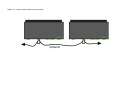
connected to the LocoNet 1 connector and the extension branch
into the LocoNet 2 connector.
Supply voltage
The booster can be supplied by DC or AC as well. In order to
achieve appropriate dissipation at the bridge rectifier of the
booster, it is definitely preferred to use AC supply.
The AC supply voltage shall never exceed 18V AC!
Connectors
The receiving possibilities of the booster synchronizing signal are
described below. Since the booster can be adapted to various
systems, it can be perfectly used if supplied from any of its inputs.
Solely fully insulated track sections with both rails cut shall
be supplied by the digital booster!
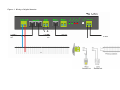
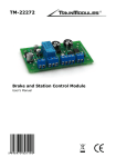
DCC OUT: Boosted signal output.
It is required to pay attention to the correct polarity during
connection. In case the isolated rail section is of reversed polarity
compared to the previous section, the booster will give a shortcircuit signal when the train changes the sections.
Only one sync source can be used at a time. The booster shall
never be used with synchronizing of rail signal and signals of other
source simultaneously.
DCC IN: Synchronizing signal can be received from the rail signal.
This can be applied if neither of the other input signals is available
or it is not required to ensure a separate synchronizing signal for
the booster.
The input can be used also for receiving the synchronizing signal of
Roco, Lenz, Tran, ESU etc. centres.
In this case it shall be considered that a short-circuit status at the
previous booster / maybe the centre can cause the breaking of the
synchronizing signal from the rail. Now the given booster will shut
down, i.e. the output will be turned off.
The input has galvanic isolation.